
Operating Instructions and Installation Instructions


Edition: 02 / 2015 Page 53 / 56
VARMAX TWIN - Installation, Use and Maintenance
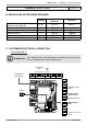
On generator No. 2
• Inputs/outputs test menu
Check the outputs
Alarm relay
Relay test (7700) Relay output QX1
Isolating valve Q1.2
Relay test (7700) Relay output QX3
Reset the outputs
Relay test (7700) No test
Check the sensor values (if 4th heating circuit present)
B1.2 fl ow sensor
Temperature sensor BX21 module 1 (7830) in °C
• Confi guration menu
Check the hydraulic diagram
Generator 1 inspection No. (6212) 14
Generator 2 inspection No. (6213) 0
DHW information (6215) 0
Information about heating circuits 3, 2 and 1 (6217) 3 (if 4th heating
circuit present)
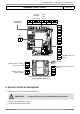
F. CONFIGURATION OPTIMISATION
On generators 1 and 2
Heating circuit optimisation
• Heating circuit 1 / 2 / 3 menu
Adjust the reduced setting
Reduced setting temperature (712/1012/1312) - - -
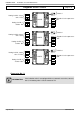
Diagrams: VX202 / VX212
page 8 / 9
Line No. Value
B12 fl ow sensor Temperature sensor BX21 module 2 (7832) in °C
B14 fl ow sensor
Temperature sensor BX21 module 3 (7834) in °C
VX212 diagram only:
Check the status of contact H1
Status of contact H1 (7841) Closed if the shunt
is in place
• Confi guration menu
Check the hydraulic diagram
Generator 1 inspection No. (6212) 14
Generator 2 inspection No. (6213) 0
DHW information (6215) 0
(VX202 diagram)
4
(VX212 diagram)
Information about heating circuits 3, 2 and 1 (6217) 30303