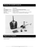
Instruction Manual Specifications Length: Height : Main Rotor Diameter: Weight with Battery: Main Motor: Battery: Charger: Transmitter: On‐Board Electronics: 10 in (255mm) 4.5 in (115mm) 8.9 in (225mm) 1.9 oz (55 g) Micro coreless (2 installed) 250mAh 1S 3.7V LiPo (included) Dual Port 1S 3.7V LiPo DC USB (included) 4‐channel 2.
Table of Contents Specifications ............................................................................................................................................ 1 Introduction .............................................................................................................................................. 3 Safety Precautions and Warnings ............................................................................................................. 4 FCC Information ..................
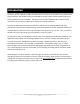
Introduction The Ares™ [air‐eez] Chronos CX 100 is the easiest way for anyone to shoot video or take photos while flying an RC heli! The CX 100’s factory‐installed digital camera is easily operated while flying by just pressing a button on the transmitter.
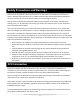
Safety Precautions and Warnings Failure to use this product in the intended manner as described in the following instructions can result in damage and/or personal injury. A Radio Controlled (RC) airplane/helicopter/quadcopter is not a toy! If misused it can cause serious bodily harm and damage to property. Keep items that could become entangled away from the propeller/rotor blades, including loose clothing, tools, etc.
Chronos CX 100 RTF Contents Item Description Not Available Separately ....... Chronos CX 100 Ultra‐Micro RTF Airframe AZSH1358M2 ......................... Micro 4‐Channel LP CX Helicopter Transmitter, Mode 2 Not Available Separately ....... AA Batteries (6pcs) AZSH1355 ............................... 250mAh 1‐Cell/1S 3.7V 15C LiPo Battery, Micro A Connector AZSC104CDUSB ...................... 1‐Cell/1S 3.7V LiPo, 0.
Before the First Flight Checklist PLEASE NOTE: This checklist is NOT intended to replace the content included in this instruction manual. Although it can be used as a quick start guide, we strongly suggest reading through this manual completely before proceeding.
LiPo Battery Warnings and Usage Guidelines IMPORTANT NOTE: Lithium Polymer batteries are significantly more volatile than the alkaline, NiCd or NiMH batteries also used in RC applications. All instructions and warnings must be followed exactly to prevent property damage and/or personal injury as mishandling of LiPo batteries can result in fire. By handling, charging or using the included LiPo battery you assume all risks associated with LiPo batteries.
When transporting or temporarily storing the battery, the temperature range should be from approximately 40–100°F. Do not store the battery or model in a hot garage, car or direct sunlight whenever possible. If stored in a hot garage or car the battery can be damaged or even catch fire. Do not over‐discharge the LiPo flight battery. Discharging the LiPo flight battery too low can cause damage to the battery resulting in reduced power, flight duration or failure of the battery entirely.
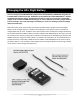
Charging the LiPo Flight Battery You must charge the included 250mAh 1‐Cell/1S 3.7V 15C LiPo Battery (AZSH1355) using only the included 104CD 1‐Cell/1S 3.7V LiPo, 0.4A Dual Port DC USB Charger (AZSC104CDUSB) or a suitably compatible LiPo battery charger.
Please follow these steps to charge the LiPo flight battery with the included charger: Connect the dual port DC USB charger to a suitable 5V USB port on a computer or other device. Another option is to plug the optional 5005PS 100‐240V AC to 5V DC USB, 0.5‐Amp Power Supply (AZSC5005PS) into a compatible 100‐240V AC outlet then to connect the charger to the power supply/AC adapter accordingly. The power supply/AC adapter is powered on when the LED indicator glows solid green.
To charge the LiPo flight battery when it’s not installed in the helicopter use the included Micro A Female Connector to Ultra‐Micro Male Connector Adapter Lead (AZSH1354) to connect the battery to the charger directly. YOU MUST BE CAREFUL TO ENSURE PROPER POLARITY BEFORE MAKING THE CONNECTIONS by orienting/aligning the wire leads of the battery and adapter lead so they’re ‘red to red’ and ‘black to black’.
Installing the Transmitter Batteries Install the six (6) included AA batteries in the back of the transmitter by first removing the battery compartment cover/door. Ensure proper polarity of the batteries before installing them as noted by the markings molded into the battery compartment, then re‐install the compartment cover/door. Check for proper operation of the transmitter by sliding the power switch to the ON position (slide it upward).
Control Mode Selection and Camera Function Button The button located near the top left‐hand corner of the transmitter has two functions. By pressing the button and holding it down while turning the transmitter on the first function is to select and set the control mode. You can select either Mode 2 or Mode 4 which will determine if the left‐hand (Mode 2) or right‐hand (Mode 4) stick controls the rudder channel. Please see the ‘Transmitter Control Mode Selection’ section of this manual for more information.
Control Mode Indicator This indicator shows which control mode is currently selected (please see the ‘Transmitter Control Mode Selection’ section of this manual for more information). The ‘2’ indicator for Mode 2 is located on the left side of the helicopter illustration and the ‘4’ indicator for Mode 4 is located on the right side. Throttle Channel Output/Stick Position Indicator This indicator shows the approximate throttle channel output/stick position.
Dual Rate Status Indicator This indicator is shows the control rate currently selected; ‘L’ for low rate and ‘H’ for high rate (please see the ‘Transmitter Dual Rates’ selection of this manual for more information). Recording Video Indicator This indicator shows when the digital camera is recording video. Still Photo Indicator This indicator shows when the digital camera is taking a still photo.
Transmitter Control Mode Selection (Mode 2/Mode 4) The Micro 4‐Channel LP CX Helicopter Transmitter included with the Chronos CX 100 features unique and exclusive software that makes it possible to select and set the ‘control mode’. Typically 3‐channel RC helicopters include transmitters that are set to ‘Mode 4’ which places throttle channel control only on the left‐hand stick and rudder and elevator channel control on the right‐hand stick.
Flight Controls and Trimming In the event you are not familiar with the controls of the Chronos CX 100 please take the time to familiarize yourself with them as follows and before attempting your first flight: Mode 2 and Mode 4 Throttle and Elevator Channel Flight Controls The left‐hand stick on the transmitter controls the throttle (climb/descend) channel. When the left‐ hand stick (also known as the ‘throttle’ stick) is in the lowest possible position the rotor blades will not spin.
The right‐hand stick controls the elevator (pitch fore/aft) channel. Pushing the stick forward will cause the ‘tail’ motor and rotor blade/propeller to spin in order to pitch the nose of the helicopter downward so it can be flown forward. Pulling the stick backward will cause the tail motor and rotor blade/propeller to spin in the opposite direction in order to pitch the tail of the helicopter downward so it can be flown backward.
Mode 2 Rudder Channel Control When the transmitter control mode is set to Mode 2 (please see the ‘Transmitter Control Mode Selection’ section of this manual for more information), moving the left‐hand stick to the left will turn (yaw) the nose of the helicopter to the left about the vertical axis. This is accomplished by increasing the speed of the upper rotor blades and decreasing the speed of the lower rotor blades.
Mode 4 Rudder Channel Control When the transmitter control mode is set to Mode 4 (please see the ‘Transmitter Control Mode Selection’ section of this manual for more information), moving the right‐hand stick to the left will turn (yaw) the nose of the helicopter to the left about the vertical axis. This is accomplished by increasing the speed of the upper rotor blades and decreasing the speed of the lower rotor blades.
Removing and Installing the LiPo Flight Battery As noted in the ‘Charging the LiPo Flight Battery’ section of this manual, you can charge the battery while it’s installed in the helicopter or you can remove and charge it separately (or ‘swap’ it with a spare battery that’s already been charged separately). To remove the LiPo flight battery you’ll first need to remove the canopy.
After making a secure connection carefully ‘tuck’ the wire leads and connectors between the control unit and battery. Re‐install the canopy by carefully sliding it over the control unit and battery while also aligning the mounting ‘slots’ inside the canopy with the mounting ‘tabs’ located on the left and right sides of the frame. Then carefully slip the left and right ends of the canopy over the mounts by aligning them with the mounting holes.
Control Unit Initialization and Arming The Chronos CX 100 is equipped with a compact and advanced 4‐in‐1 control unit. The control unit is a lightweight combination of a 2.4GHz receiver, three electronic speed controls (ESCs), a mixer and gyro. The control unit is also equipped with an LED that provides various indications.
With the throttle stick in the lowest possible position ensure that the stick is ‘centered’ left to right and that the right‐hand stick is ‘centered’ left to right as well as up and down. DO NOT move the sticks as you turn the transmitter on to avoid changing the proper center/neutral positions of the controls.
In case the LED indicator does not change to glow solid red: If the LED indicator on the control unit continues to blink/flash slowly you do not have a positive radio frequency (RF) link between the transmitter and the receiver in the control unit. First, check to be sure the transmitter is powered on and that the LED indicator on the transmitter is glowing solid red. If the transmitter is powered on and functioning properly, turn the helicopter off then turn the transmitter off.
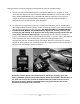
Flying Now that you’ve selected a suitable flying area you’re ready to fly! And when making your first flights we suggest following these steps: Increase the speed of the rotor blades until the model begins to lift off by raising the left‐ hand/throttle stick SLOWLY. DO NOT raise the stick too quickly as the model could climb too fast causing you to lose control and/or make contact with the ceiling or other objects above (this is one of the most common ways most first‐time pilots crash).
Continue to practice until you’re comfortable hovering the helicopter at approximately 18‐24 inches high. Then you can transition to hovering the helicopter at higher altitudes of approximately three to four feet. If at any time during flight you feel like the helicopter is drifting out of/beyond your control, simply release all of the controls except for throttle.
Digital Video/Still Camera The factory‐installed Digital Video/Still Camera is easy to operate and allows you to capture video and still photos during flight. The included 2GB MicroSD card can store up to 90 minutes of video or hundreds of photos that are easy to access using the included USB cable. The following steps outline how to use the digital camera: The camera will power on automatically when the helicopter is turned on.
When only the blue color status LED on the camera is glowing solid the MicroSD card is installed, the camera is powered on and ready to record video/take still photos. After pressing the camera function button once the red status LED will also glow solid indicating that the camera is recording video. Pressing the camera function button again will stop the recording and the red status LED will turn off.
Transmitter and Receiver Binding/Linking Binding/linking is the process of programming the receiver in the control unit to recognize the Globally Unique Identifier (GUID) code of a single specific transmitter.
Replacement Parts List Item Number AZSC104CDUSB AZSH1353 AZSH1354 AZSH1355 AZSH1356 AZSH1358M2 AZSH1359 AZSH1360 AZSH1361 AZSH1362 AZSH1363 AZSH1364 AZSH1365 AZSH1366 AZSH1367 AZSH1368 AZSH1369B AZSH1369R AZSH1370 AZSH1371B AZSH1371R AZSH1372 AZSH1373 Description 104CD 1‐Cell/1S 3.7V LiPo, 0.4A Dual Port DC USB Charger, Ultra‐Micro Connector Ultra‐Micro Male to Male Connector Adapter Lead Micro A Female Connector to Ultra‐Micro Male Connector Adapter Lead 250mAh 1‐Cell/1S 3.
Exploded View Parts Listing Exploded View # 1 2 3 4 5 6 7 8 9 10 11 12 13 14 15 16 17 18 19 20 21 22 23 24 25 26 27 28 29 30 31 32 33 34 35 36 Description (Total Quantity Used) Upper Main Rotor Blade (2) Stabilizer Flybar/Upper Main Rotor Blade Linkage (2) Upper Rotor Head/Hub (1) Stabilizer Flybar (1) M1.4x6mm Screw (4) Rotor Head/Shaft Spacer (1) Lower Main Rotor Blade (2) Lower Rotor Head (1) Lower Rotor Head Shaft (1) Inner Shaft (1) M1.4x6mm Screw (4) Main Motor (2) Battery (1) Canopy (1) M1.
Exploded View 33
Notes This equipment has been tested and found to comply with the limits ____________________________________________________________________________ for a Class B digital device, pursuant to Part 15 of the FCC Rules.
Notes ____________________________________________________________________________ ____________________________________________________________________________ ____________________________________________________________________________ ____________________________________________________________________________ ____________________________________________________________________________ ____________________________________________________________________________ ____________________________________________
www.Ares-RC.com © 2013 Rev 09.20.