FIELD MOUNTED RATE TOTALISER MODEL 202D 1 February 1999
CONTENTS 1. Introduction 1.1 Model Number Designation 1.2 Intrinsic Safety Considerations 1 3 4 2. Specification 6 3. Operation 3.1 Display 3.2 Test Mode 3.3 Filtering 3.4 Calculation of Rate and Total 3.5 Total Conversion 3.6 Frequency Cutoff 8 8 9 10 12 13 14 4. Programming 4.1 Program Steps 15 16 5. Example 19 6. Versions 6.1 Battery Powered Version 6.2 DC Power Version 6.3 Relay and 4-20mA Output Version 20 21 22 24 7. Flowmeter Input 26 8. Intrinsic Safety Connections 8.1 Coils 8.
9. Installation 9.1 Wall Mounting 9.2 Panel Mount Version 9.3 Removing the Front Panel 9.4 The Main Electronics 9.5 Wiring 9.
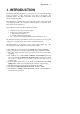
Introduction 1 1. INTRODUCTION The Model 202D Rate Totaliser is a microprocessor based instrument which accepts a frequency or pulse input from a wide range of flowmeters. The instrument displays flow Rate, a Resettable Total and an Accumulated Total directly in engineering units. The instrument is compatible with a wide range of flowmeters. Links on the input board enable the circuit to be configured for millivolt signals, reed switches, pulse trains and most other signal types.
2 Introduction ♦ Unlike the previous Model 202, the 202D has an additional mounting option it is available in a PANEL MOUNT version. The Model 202D Rate Totaliser conforms to the EMC-Directive of the Council of European Communities 89/336/EEC and the following standards: Generic Emission Standard EN 50081-1 Residential, Commercial & Light Industry Environment. Generic Emission Standard EN 50081-2 Industrial Environment.
Introduction 3 1.1 MODEL NUMBER DESIGNATION The Model Number of the 202D describes the power & output options installed and the mounting options. Model 202D .
4 Introduction 1.2 INTRINSIC SAFETY CONSIDERATIONS The Model 202D is certified for use in hazardous areas and has both CENELEC and CSA NRTL/C approvals. The Model 202D certification details are: CENELEC Approval: Type of Protection: Group: Temperature Class: Kema 98.E.1873. Ex ia. IIB. T4 at ambient temperature of 60°C. CSA NRTL/C Approval File Number: Type: LR 104 840-5. Class 1, Groups C and D.
Introduction 5 Relay Outputs The outputs can be connected to IS circuits with the following maximum values: Ui = 28V Ii = 93mA Pi = 653mW The internal capacitance and inductance seen on these terminals is 0.1uF and 0mH. Flowmeter Input Entity parameters on the flowmeter enable connection to a wide range of approved sensors. Input parameters are: Ui = 24V Ii = 20mA Pi = 320mW The internal capacitance and inductance seen on these terminals is 0.002uF and 0mH. Output parameters are: Uo = 10.0V Io = 9.
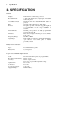
6 Specification 2. SPECIFICATION General Display: Resettable Total: Accumulated Total: Rate: K-factor: Decimal Points: Timebase: Frequency Range: Signal Type: LCD which is continuously powered. 7 digits with 10mm (0.4") high digits. Resettable from front panel. Displayed when the ACCUM TOTAL button is pressed. 4½ digits with 8.5mm (0.33") high digits. The pulses per unit of measure (eg. pulses/gallon) is programmable in the range 0.000001 to 999,999.
Specification 7 DC Power/Alarm Version Outputs: Switching Power: DC Power Input: Supply Backup: Pulse Duration: Two open collector outputs suitable for driving DC solenoids or external relays. The outputs can be programmed to provide high and low flow alarms or pulse output and low flow alarm. 200mA. 30VDC maximum. 9-28 Volt at 4mA maximum. Lithium battery. 1ms if CAL0 = 2 (unscaled pulse output).
8 Operation 3. OPERATION The Model 202D Rate Totaliser accepts a frequency or pulse input from a wide range of flowmeters. The instrument is fully programmable with all operating parameters and calculation constants programmable from the front panel. The setup parameters are stored in a non-volatile memory and are retained for at least 40 years in the event of a power loss. 3.
Operation 9 3.2 TEST MODE The 202D has a Test Mode which can be entered by simultaneously pressing all 3 front panel keys. The tests are as follows: Low Test By pressing the ACCUM TOTAL key, the low alarm output (if installed) will go low. If a 420mA option is installed, the output will go to 4mA. High Test By pressing the RESET key, and depending on the programmed pulse output mode, the high alarm output (if installed): a. will go low if CAL0 = 0 (high alarm output). b.
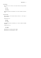
10 Operation 3.3 FILTERING Frequency fluctuations caused by pulsating flow through a flowmeter can interfere with the precision of the rate. For this reason, the Model 202D has a digital filter which will average out these fluctuations and enable accurate readings. The degree of filtering of the input signal can be adjusted depending on the amount of fluctuation and the particular application. Values from 1 to 99 can be programmed where 1 corresponds to no filtering and 99 corresponds to heavy filtering.
Operation Filter Factor vs Time to Reach New Reading (for a step change in input signal) Time to Reach % of New Reading (seconds) 120 100 80 60 40 20 0 0 10 20 30 40 50 60 70 80 90 Filter Factor 90% of New Reading 99% of New Reading 100 11
12 Operation 3.4 CALCULATION OF RATE AND TOTAL The flow rate, R, is calculated as follows: R= f xH S where f is the input frequency in Hz (pulses/second). H is the timebase of rate and is 1 for seconds, 60 for minutes, 3600 for hours and 86,400 for days. S is the scaling factor (pulses/unit volume). The scaling factor, S, is equal to the K-factor of the flowmeter expressed in pulses per unit volume. The K-factor is flowmeter dependant and is supplied with the flowmeter.
Operation 13 3.5 TOTAL CONVERSION The Total Conversion Factor is programmed to enable the rate to be displayed in one engineering unit and the totals to be displayed in another. For example, the rate can be displayed in gallons/minute and the totals in barrels. The Total Conversion Factor is a division factor which is used to convert the totals to a different unit. Therefore, it only affects the totals (both resettable and accumulated). Example. If the Rate is required in gallons/minute: 1.
14 Operation 3.6 FREQUENCY CUTOFF A frequency cutoff can be programmed below which flow rate is not registered. Input frequencies at or below the cutoff are totalised, however, the rate is displayed as zero. The frequency cutoff has a default value of 0.25Hz. The cutoff should be left as 0.25Hz unless the flowmeter in use has a lower frequency. Note that a low cutoff frequency will result in a correspondingly low response of flow rate update. For example, if the cutoff is set to 0.
Programming 15 4. PROGRAMMING The Model 202D is fully programmable with all parameters being stored in nonvolatile memory. The Program Mode can be entered in one of two ways: 1. By removing the lower cover strip (ie. the dark grey strip along the bottom of the enclosure) and replacing it the wrong side up. This brings a small magnet on the inside of the cover strip in contact with a reed switch inside the instrument. 2.
16 Programming 4.1 PROGRAM STEPS Step Comment CAL 0 Pulse Output (applies to DC Power/Alarm version only). 0 = No pulse output, low and high alarms. 1 = Scaled pulse output and low alarm. 2 = Unscaled pulse output and low alarm. CAL 1 Scaling Factor - whole numbers. CAL 2 Scaling Factor - digits after the decimal point. The scaling factor is the pulses per unit of measure (eg. pulses/litre, pulses/gallon, etc). The scaling factor can be programmed in the range of 0.000001 - 999,999. See Section 3.
Programming Step Comment CAL 6 Filter. 17 The filter constant for filtering the input signal. 1 No filtering. to 99 Very heavy filtering. CAL 7 Decimal Point for Total Display. The totals can be displayed with 0, 1, 2 or 3 decimal points. CAL 8 Total Conversion Factor - whole numbers. CAL 9 Total Conversion Factor - digits after the decimal point. The total conversion factor enables the rate to be displayed in one engineering unit and the totals to be displayed in another engineering unit.
18 Programming Step Comment CAL 12 High Alarm or Pulse Output Factor - whole numbers. CAL 13 High Alarm or Pulse Output Factor - digits after the decimal point. CAL 12 & 13 program the flow rate above which the high alarm relay will close. The value can be programmed in the range 0 to 999,999. If the scaled pulse output is selected (see CAL0 = 1), then the value will represent the total per pulse, eg. 5 litres per pulse. CAL 14 4mA Retransmission - whole numbers.
Example 19 5. EXAMPLE A flowmeter produces 20.538 pulses per litre and has a maximum output frequency on 200Hz. It is required to display the flow rate in litres/min with 1 decimal point and the total in litres with no decimals. A 4-20mA output is installed and 4mA is to represent 0 litres/m and 20mA is to represent 500 litres/m. The instrument is then programmed as follows: Calibration mode is entered by removing the lower cover strip (ie.
20 Versions 6. VERSIONS The following table summarises the features of each of the different versions of the Model 202D: Model Number 202D.X0 202D.X3 202D.
Versions 21 6.1 BATTERY POWERED VERSION The battery powered version of the Model 202D is designed for operation in the field without external power sources. Lithium batteries provide sufficient power to operate the instruments for up to 5 years and the operator is warned of a low power condition by a message on the LCD display. New batteries can be purchased via Contrec or our distributors and replaced in the field without compromising the IS approvals.
22 Versions 6.2 DC POWER VERSION The DC power version will operate from an external power source between 928VDC and draws no more than 4mA. This enables the instrument to be powered from AC mains adaptors and eliminates the need to run mains voltages in the field. The instrument uses lithium batteries for backup if the DC power is interrupted. However, alarms and/or pulse outputs are not supported if the DC power is interrupted. Open collector outputs are also provided for high and low flow rate alarms.
Versions 23 Specification for Alarm Outputs Maximum Current (sink): Maximum Voltage: Saturation Voltage: Isolation: Pulse Frequency: Pulse Duration: 200mA. 30Vdc. 0.8Vdc across outputs when in the "on" state. Both outputs are separately isolated. 500Hz maximum. 1ms if CAL0 = 2 (unscaled pulse output). If CAL0 = 1 (scaled pulse output) the duration of the pulse automatically adjusts to the output frequency: a. 1ms if output > 50Hz. b. 10ms if output = 5...50Hz. c. 100ms if output < 5Hz.
24 Versions 6.3 RELAY AND 4-20mA OUTPUT VERSION This version combines features of the DC powered with a 4-20mA output. The 4-20mA output provides a two-wire retransmission of the flow rate. Both the 4mA and 20mA points are fully programmable so that the output can span across the entire operating range or, alternatively, across a small section of the operating range. The instrument draws its operating power from the 4-20mA loop and uses lithium batteries for backup if the 4-20mA loop is interrupted.
Versions Typical Connection Connection to a Sensor requiring External Power 25
26 Flowmeter Input 7. FLOWMETER INPUT The Model 202D has an input conditioning circuit which will accept signals from most pulse or frequency producing flowmeters. Links on the rear panel enable the input circuit to be configured for different signal types. The input will interface directly to: ♦ ♦ ♦ ♦ ♦ Turbine flowmeters. Open collector outputs. Reed switches. Logic signals. Two-wire proximity switches. The following pages give examples of interconnection to various signal outputs.
Flowmeter Input 27
28 Flowmeter Input 1. Squarewave, CMOS or Pulse Link Settings COIL PULSE DB DBH Link 1 Link 2 Link 3 NPS Switching threshold voltage is 1.3 volts. 2. Open Collector With 15µA/150µA internal pull up current Link Settings COIL PULSE DBL DBH Link 1 Link 2 Link 3 NPS 3. Reed Switch - Battery Powered Link Settings With 15µA internal pull up current COIL PULSE DBL DBH Link 1 Link 2 Link 3 NPS eg. Positive displacement flowmeters with reed switch outputs.
Flowmeter Input 4. Reed Switch - External DC Power 29 Link Settings With 150µA internal pull up current COIL PULSE DBL DBH Link 1 Link 2 Link 3 NPS Note: For a switch or reed input with contact bounce link DBH can be switched "on". This will eliminate the effect of switch bounce while limiting the input frequency to 200Hz. 5. Coils Link Settings COIL PULSE DB DBH Link 1 Link 2 Link 3 NPS 825R input impedance eg. Millivolt signal from paddlewheel or turbine (15mV P-P minimum).
30 Flowmeter Input 6. Namur Proximity Switch Link Settings COIL PULSE DBL DBH Link 1 Link 2 Link 3 NPS 825R input impedance For IS connections of Namur switches see Section 8. Note: Use this connection for a DC powered version of the Model 202D. 7. Namur Proximity Switch - External DC Power Link Settings COIL PULSE DBL DBH Link 1 Link 2 Link 3 NPS 825R input impedance For IS connections of Namur switches see Section 8.
Intrinsic Safety Connections 31 8. INTRINSIC SAFETY CONNECTIONS When installing the Model 202D in hazardous areas, the wiring and installation must comply with appropriate installation standards. The approval uses entity parameters on the input for connections to the flowmeter and associated apparatus type approval for the 4-20mA output. The 4-20mA output must, therefore, only be connected to barriers with the specified safety parameters as shown on the following page. 8.
32 Intrinsic Safety Connections 8.2 SIMPLE APPARATUS Devices such as reed switches which can be classed as "simple apparatus", as defined in the CENELEC standards EN50020, can be connected to the Model 202D without certification. 8.
Intrinsic Safety Connections 33
34 Intrinsic Safety Connections
Intrinsic Safety Connections 35 8.4 ALARM OUTPUTS The low alarm and high alarm/pulse output can be connected to suitably certified devices providing the circuit is protected with a barrier with the maximum safety parameters: Uo = 28V Io = 93mA Pmax = 0.653W The input capacitance on these terminals is 0.1uF max and the inductance is negligible. Note that the two alarm outputs must be kept as independent IS circuits and each protected with their own barrier.
36 Intrinsic Safety Connections
Installation 37 9. INSTALLATION 9.1 WALL MOUNTING A wall mounting bracket is supplied with each instrument. Round head screws should be used to attach the bracket to the wall (countersunk screws should not be used). The bracket is mounted first with the tray section at the bottom. The instrument is then mounted on the bracket with two screws as shown below.
38 Installation 9.2 PANEL MOUNT VERSION The panel mount version of the Model 202D is supplied with two panel mount brackets and plug-in terminals which are accessible from the rear of the instrument. A diagram of the rear panel is shown below: Rear View of 202D Panel Mount Case The cutout for the panel mount version is 141mm (5.55") wide x 87mm (3.43") high.
Installation 39 9.3 REMOVING THE FRONT PANEL The front panel should be removed as follows: 1. Remove the top and bottom cover strips (ie. the dark plastic strip) by levering a screwdriver under one end. 2. Undo the screws retaining the front. Do not remove the screws, they are retained by O-rings. 3. Remove the front panel from the housing. To replace the front cover, follow the above procedure in reverse. Ensure that the front panel is aligned at connector points before tightening the screws.
40 Installation
Installation 41 9.4 THE MAIN ELECTRONICS The front section of the housing contains the microprocessor and display. It is possible to adjust the display contrast via a small potentiometer on the board. The Display Contrast is shown below and this can be adjusted for optimum contrast. Adjacent to this control is a RESET switch which can be used to reset the microprocessor. Note that pressing this button will set all totals to zero.
42 Installation 9.5 WIRING When connecting the 202D it is good practice to use shielded cable. The shield should be connected to earth at one end of the cable. The other end of the shield should not be connected. This wiring practice is mandatory in order to comply with the requirements for Electromagnetic Compatibility as per EMC-Directive 89/336/EEC of the Council of the European Community.
Installation 9.
44 Index Index Intrinsic Safety, 4, 31 4-20mA Output, 24 Link Settings, 28 Low Alarm, 17 Low Test, 9 A Accumulated Total, 8 Alarm Outputs, 35 L M Model Number, 3 B Battery Powered, 21 C CAL Sequences, 15 Cutoff Frequency, 16 D DC Power, 22 Decimal Point, 16, 17 Display, 6, 8 Display Test, 9 F Filtering, 10 Flow Rate, 12 Frequency Cutoff, 14 H High Alarm, 18 High Test, 9 I Input Signal, 26 Installation, 35 O Operating Temperature, 7 Operation, 8 P Panel Mount, 36 Programming, 15 Protection, 7