FIELD MOUNTED RATE TOTALISER MODEL 202A 2 August 1999
CONTENTS 1. Introduction 1.1 Model Number Designation 1.2 Operation 1.3 Intrinsic Safety Considerations 3 4 6 7 2. Specification 8 3. Programming 3.1 Program Steps 3.2 Calculation of Rate and Total 3.3 Total Conversion 3.4 Filtering 3.5 Example 10 11 14 16 17 19 4. Signal Input 20 5. Alarm & Pulse Outputs 21 6. Intrinsic Safety Connections 23 7. Installation 7.1 Wall Mounting 7.2 Panel Mount Version 7.3 Removing the Front Panel 7.4 The Main Electronics 7.5 Wiring 7.
Introduction 3 1. INTRODUCTION The Model 202A Rate-Totaliser is a microprocessor based instrument designed to measure a 4-20mA signal from flowmeters and pressure transducers. The instrument can be programmed to display directly in engineering units and includes features such as linear or square law calculation, integration and digital filtering. Rate, Total and Accumulated Total can be displayed in engineering units on the large LCD display.
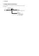
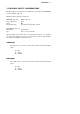
4 Introduction 1.1 MODEL NUMBER DESIGNATION The Model Number of an instrument describes which input and output options are installed. Model 202 A.
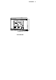
Introduction The Model 202A 5
6 Introduction 1.2 OPERATION The Model 202A Rate Totaliser will display: Rate Resettable Total Accumulated Total. Both the Rate and Resettable Total are continuously displayed while the Accumulated Total is only displayed when the ACCUM TOTAL key is pressed. The Resettable Total can be reset at any time by pressing the RESET key. The instrument also has a test mode which can be entered by simultaneously pressing all three front panel keys.
Introduction 7 1.3 INTRINSIC SAFETY CONSIDERATIONS The Model 202A is certified for use in hazardous areas and has both CENELEC and CSA NRTL/C approvals. The Model 202A certification details are: CENELEC Approval: Type of Protection: Group: Temperature Class: Kema 98.E.1873. Ex ia. IIB. T4 at ambient temperature of 60°C. CSA NRTL/C Approval File Number: LR 104 840-5. Type: Class 1, Groups C and D.
8 Specification 2. SPECIFICATION General Display: Resettable Total: Accumulated Total: Rate/Display: Span: Decimal Points: Timebase: Signal Type: LCD, which is continuously powered. 7 digits with 10mm (0.4") high digits. Resettable from front panel. Displayed when the Accumulated Total button is pressed. 5 digits with 8.5mm (0.33") high digits. The units of measure per timebase (eg. gallons/sec) is programmable in the range 0.000001 to 999,999.
Specification 9 Outputs Type: Switching Power: Saturation Voltage: Isolation: Pulse Duration: (for pulse output) Two open collector outputs suitable for driving DC solenoids or external relays. The outputs provide high and low flow alarms or pulse output and low flow alarm. 200mA. 30VDC maximum. 0.8VDC typical across the output in the "on" state. Both outputs are separately opto-isolated. If CAL00 = 1 (scaled pulse output): a. 1ms if output frequency > 50Hz, b. 10ms if output frequency is 5 ... 50Hz, c.
10 Programming 3. PROGRAMMING The Model 202A is fully programmable, with all parameters being stored in non-volatile memory. The Program Mode can be entered in the following way: By removing the lower cover strip (ie. the dark grey strip along the bottom of the enclosure) and replacing it the wrong side up. This brings a small magnet on the inside of the cover strip in contact with a reed switch inside the instrument.
Programming 11 3.1 PROGRAM STEPS Step CAL 00 Comment Pulse Output 0 = No pulse output, low and high alarms 1 = Scaled pulse output and low alarm CAL 01 Span - whole numbers. CAL 02 Span - digits after the decimal point. The Span is the number of units of measure per timebase (eg. litres/sec, Gal/min). The Span can be programmed in the range of 0.000001 - 999,999. See section 3.2. CAL 03 Cutoff Point. This determines the cutoff point as a fraction of Span. See section 3.2.2.
12 Programming Step CAL 06 Comment Filter. Fluctuations in the flowrate can be filtered out so that the Rate is held steady. The filter value is programmed between 1 - 99 where "1" represents no filtering and 99 is maximum. See section 3.4. CAL 07 Decimal Point for Total Display. The totals can be displayed with 0, 1, 2 or 3 decimal points. CAL 08 Total Conversion Factor - whole numbers. CAL 09 Total Conversion Factor - digits after the decimal point.
Programming Step Comment CAL 11 Low Alarm - digits after the decimal point. 13 CAL 10 & 11 program the flowrate below which the low alarm relay will close. The value can be programmed in the range 0 to 999,999. CAL 12 High Alarm or Pulse Output Factor - whole numbers. CAL 13 High Alarm or Pulse Output Factor - digits after the decimal point. CAL 12 & 13 program the flowrate above which the high alarm relay will close. The value can be programmed in the range 0 to 999,999.
14 Programming 3.2 CALCULATION OF RATE AND TOTAL 3.2.1 Analog Input The flowrate, R, is calculated as follows: or R = SA if the linear relationship is selected R=S A if a square law relationship is selected. where A = the input value. S = the span. At the minimum input (ie. 4mA), A = 0, and at the maximum input (ie. 20mA), A = 1. The Span, S, can be set during calibration anywhere in the range of 0.000001 to 999,999. The Span, S, is programmed in units of volume per timebase (ie.
Programming 15 3.2.2 The Cutoff Point Because many transducers do not always exactly transmit 4mA when they are at zero rate, it is often necessary to define a rate below which no integration takes place. This is termed the cutoff point and is programmed as a percentage of the Span, S. For example, if S = 2200 kg/min in a square law system, and the cutoff point is set at 20.
16 Programming 3.3 TOTAL CONVERSION The Total Conversion feature enables the rate to be displayed in one engineering unit (eg. gallons/minute) and the totals to be displayed in another engineering unit (eg. barrels). The Span is always programmed in the unit relating to Rate, and the Total Conversion constant is a division factor which can be used to convert the totals to the different unit. The Total Conversion factor affects the resettable and accumulated totals. For Example.
Programming 17 3.4 FILTERING Frequency fluctuations caused by pulsating flow through a flowmeter, often makes the Rate impossible to read with any precision. The Model 202A has a digital filter which will average out these fluctuations and enable the Rate to be read to four digit accuracy. The ability to select a suitable filtering level means that highly accurate and stable readings can be obtained without excessive lag.
18 Programming A 90% 99% 1 0 0 2 1 2 4 2 4 6 3 6 10 5 11 15 8 17 20 11 22 25 14 28 35 20 40 45 25 51 60 34 69 75 43 86 90 52 103 99 57 113 Table 1 - Response to a step Input (in seconds). Note that if CAL 06 is set to 01 there is no filtering of the input signal.
Programming 19 3.5 EXAMPLE A vortex flowmeter has a maximum output of 20.538 litres/min at 20mA. It is required to display the flowrate in litres/min with 1 decimal point and the total in litres with no decimals. High and low alarms are required at 18 l/m and 2 l/m respectively. The instrument is then programmed as follows. CAL00 0 No Pulse Output CAL01 00020 CAL02 5380 Span (Decimals) 03 0.
20 Signal Input 4.
Alarm & Pulse Outputs 21 5. ALARM & PULSE OUTPUTS Open collector outputs are provided for high and low flowrate alarms. The output can sink up to 200mA and can be used to power external relays, lights or audible alarms. The outputs are internally protected against voltage spikes caused by relays and coils. Both outputs are separately isolated via opto isolators. As an alternative to a high flowrate alarm, the output on terminals 7 and 8 can be programmed to output a scaled pulse output.
22 Alarm & Pulse Outputs Connections
Intrinsic Safety Connections 23 6. INTRINSIC SAFETY CONNECTIONS When installing the Model 202A in hazardous areas, the wiring and installation must comply with appropriate installation standards. The approval uses entity parameters and an associated apparatus type approval on the input/output connections to the 4-20mA current loop and alarms. The 4-20mA input and alarm outputs must, therefore, only be connected as shown on the following page, to barriers with the specified parameters.
24 Intrinsic Safety Connections
Installation 25 7. INSTALLATION 7.1 WALL MOUNTING A wall mounting bracket is supplied with each instrument. The bracket should be attached to the wall using round head screws (do not use counter sunk screws). The bracket is mounted with the "tray" section at the bottom. The instrument is then attached to the bracket at the bottom with two screws (see diagram below).
26 Installation 7.2 PANEL MOUNT VERSION The panel mount version of the Model 202A is supplied with two panel mount brackets and plug-in terminals which are accessible from the rear of the instrument. A diagram of the rear panel is shown below. The cutout for the panel mount version is 141mm (5.55") wide x 87mm (3.43") high.
Installation 27 7.3 REMOVING THE FRONT PANEL The front of the instrument is removed as follows: 1. Remove both the top and bottom cover strips (ie. the dark plastic strips on the front) by levering a screwdriver under one end. 2. Undo the seven screws retaining the front. Note that the screws should not be removed from the front panel as they are retained by O-rings. 3. Pull the front panel free from the housing. Replacing the front panel of the instrument is the reverse procedure.
28 Installation
Installation 29 7.4 THE MAIN ELECTRONICS The front section of the housing contains the microprocessor and display. It is also possible to adjust the display contrast via a small potentiometer on the board. The DISPLAY CONTRAST control is shown below and this can be adjusted for optimum contrast. Adjacent to this control is a RESET switch which can be used to reset the microprocessor. Note that pressing this button will Set all totals to zero and calibration parameters to default values.
30 Installation 7.5 WIRING When connecting the Model 202A, it is goods practice to use shielded cable. In order to comply with the requirements for Electromagnetic Compatibility, as per EMC-Directive 89/336/EEC of the Council of the European Community, this wiring practice is mandatory.
Installation 7.
32 Index Index A Accumulated Total, 6 C CAL Sequences, 10 Cutoff Point, 11 D Decimal Point, 11 Display, 8 Display Test, 6 F Filtering, 17 H Hi Test, 6 High Alarm, 13 I Installation, 25 Intrinsic Safety, 7 O Operating Temperature, 9 Operation, 6 P Panel Mount, 26 Programming, 10 Protection, 9 Pulsating Signal, 17 Pulse Output, 21 R Rate, 6 Removing the Front Panel, 27 Resettable Total, 6 Response, 18 S Span, 11 Specification, 8 T Lo Test, 6 Low Alarm, 12 Temperature, 9 Terminal Designations, 31