GAS & STEAM FLOW COMPUTER MODEL 415 6 December 1999
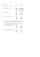
CONTENTS List of Symbols 1. Introduction 1.1 Model Number Designation 7 9 2. Specification 10 3. Operation 14 3.1 Front Panel Operation 3.2 Flow Equations for Gases 3.2.1 Ideal Gas Law 3.2.2 General Gas 3.2.3 Natural Gas 3.3 Steam Measurement 3.4 Filtering 3.5 Non-Linearity Correction 3.5.1 Digital Input Linearity Correction 3.5.2 Analog Input Linearity Correction 3.6 The Output Pulse 4. Options 4.1 The 4-20mA Output Option 4.1.1 Load Specification 4.1.2 Calculation 4.
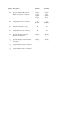
5. Calibration 5.1 Programming Chart 5.2 Definitions 6. Input Circuits 6.1 Frequency Flow Input 6.2 Analog Inputs 6.3 Remote Switches (Model 415A Only) 7. Installation 7.1 General 7.
List of Symbols Used in this Manual Symbol Description SI Units US Units A Normalised signal from the flowmeter which will be 0 at 4mA and 1 at 20mA. G Specific Gravity for Gas. hB Specific Enthalpy at Reference Conditions. kJ/kg kJ/kg hF Specific Enthalpy at Flow Conditions. kJ/kg kJ/kg KF K-factor (pulses/unit) for a frequency flowmeter.
Symbol Description SI Units US Units kPa (abs) psia PF Pressure at flow conditions. QE Energy value of steam. MJ/day MJ/hr MJ/min MJ/sec BTU x 1000/day BTU x 1000/hr BTU x 1000/min BTU x 1000/sec QM Mass Flowrate. kg/day kg/hr kg/min kg/sec lbs/day lbs/hr lbs/min lbs/sec QVB Volume Corrected Flowrate. m3/day m3/hr m3/min m3/sec ft3/day ft3/hr ft3/min ft3/sec Note: If the corrected flowrate is at standard base conditions, then the flow will be in scm or scf (ie.
Symbol Description SI Units US Units SVB Span (Volumetric Flowrate at 20mA) and at base conditions. m3/day m3/hr m3/min m3/sec ft3/day ft3/hr ft3/min ft3/sec TB Temperature at base conditions. °K (Kelvin) °R (Rankin) TC Critical temperature of gas. °K °R TF Temperature at flow conditions. °K °R νB Specific Weight of Steam at Reference Conditions. dm3/kg dm3/kg νF Specific Weight of Steam at Flow Conditions. dm3/kg dm3/kg Zb Compressibility at base conditions.
Introduction 7 1. INTRODUCTION The Model 415 Gas Flow Computer incorporates compensation for gas and vapours to the following equations: 1. Ideal Gas Law using temperature & pressure correction, but where compressibility is ignored. 2. General Gases where compressibility is calculated using the Redlich-Kwong1 equation. 3. Natural Gas using NX-192 equation for supercompressibility. 4. Steam Equations for both saturated and superheated steam.
8 Introduction This instrument conforms to the EMC-Directive of the Council of European Communities 89/336/EEC and the following standards: Generic Emission Standard EN 50081-1 Residential, Commercial & Light Industry Environment. Generic Emission Standard EN 50081-2 Industrial Environment. Generic Immunity Standard EN 50082-1 Residential, Commercial & Light Industry Environment. Generic Immunity Standard EN 50082-2 Industrial Environment.
Introduction 9 1.1 MODEL NUMBER DESIGNATION The Model number of an instrument describes which input and output options are installed and the AC mains voltage rating. Model 415 R.
10 Specification 2. SPECIFICATION General Display: Keyboard: Transducer Supply: Power Requirements: Operating Temperature: Facia: Dimensions: Depth behind Panel: Alphanumeric LCD display with backlighting and 2 lines x 20 characters/line. Each character 5.5mm high. Sealed membrane keyboard with four keys. 8-24VDC field adjustable, 65mA maximum. 14 to 28.0 VDC, 300mA typical. AC mains - Set internally to 95 - 135 VAC or 190 - 260 VAC. 0 to 55°C. Watertight to IP65 or Nema 3S. 144mm (5.
Specification 11 4-20mA Inputs Inputs: Input Impedance: Measurement Ranges: Accuracy: Circuit: Span (Flow): Flow (2), pressure & temperature. 250 ohms. Pressure: 0kPa (abs) (0 psia) to 100,000 kPa (10,000 psia). Temp:-273°C (-459.4°F) to 1200°C (2192°F). 0.05% The 250 ohm resistors are connected to a common signal ground (current sinking). 999,999.
12 Specification Relay Output Function: High and low flowrate alarms based on the flowrate selected as the default display. Maximum Switching Power: 1250VA. Maximum Switching Voltage: 250 VAC, 30VDC. Maximum Switching Current: 5 Amps. RS232/422/485 Option Type: Function: Output: Baudrate: Data Bits: Parity: Both RS232 & RS422/485 are provided. Printer and computer protocols are programmable. Output is on request or at a programmable time interval. 300 to 9600. 7 or 8. None, Odd, Even.
Specification 13 General Gas Gases: Compressibility: Display: Temperature Range: Pressure Range: Handles most gases for which the critical temperature, pressure and SG are known. Calculated using Redlich-Kwong equation. Corrected Volume (m3 or ft3). Mass (kg or lbs). -273°C (-450°F) to 800°C (1472°F). (RTD has a more limited range.) 0 kPa abs (0 psia) to 100,000 kPa (10,000 psia).
14 Operation 3. OPERATION The Model 415 uses a low power CMOS microprocessor to perform all measurement and control functions. The instrument is fully programmable with all operating parameters and calculation constants user programmable (see Section 5 entitled Calibration for information on programming). All parameters and constants are stored in a non-volatile memory which retains data without battery backup for a minimum of 10 years. 3.
Operation 15 Steam Mass Energy Temperature & Pressure Specific Weight & Enthalpy (Rate & Total) (Rate & Total) If any value other than the default display values are selected, they will remain displayed for 5 seconds, after which the display will automatically revert to the default values. Totals are displayed with a maximum of 8 digits, including decimals. For example, if two decimals are programmed, the maximum total is 999,999.99, after which the totals roll over to zero and continue counting.
16 Operation 3.2 FLOW EQUATIONS FOR GASES This section applies only to gas flow measurement and, if the Model 415 is to be used for steam measurement, the reader can skip this section and go to section 3.3. The Model 415 will accept inputs from a wide range of flowmeters with the flowrate calculated by the equations defined below. Both mass flow and volume corrected flow to a base temperature and pressure are calculated and displayed in either SI (metric) or US units.
Operation 17 Normalised Conditions (SI Units only) Normalised conditions are defined as: 0°C (273.15°K) and 101.325 kPa. A. Volumetric Flowmeters With Frequency Output. eg. Vortex, turbine or positive displacement flowmeters. Q VB = N. frequency(Hz) KF . PF PB . TB TF . ZB ZF ......(4) Q M = ρ B . Q VB B. ......(5) Volumetric Flowmeters With 4-20mA Output. eg. Vortex, turbine or positive displacement flowmeters with frequency to current convertors. Q VB = S V . PF PB . TB TF . ZB ZF ..
18 D. Operation Differential Pressure Flowmeters With 4-20mA Output And With A Linear Flow Relationship. eg. D.P. transmitters with a square root extractor or VA meters. Q VB = S VB . PF PB . TB TF . ZB ZF .A ......(8) Q M = ρ B . Q VB Note that the pressure and temperature are still square rooted, even though the flow signal A is not. This is because the output from the D. P. transmitter is not truly volumetric, but will be affected by a change in density of the gas being measured.
Operation 19 Example 1 Flow is to be measured across an orifice in the range of 0 - 2000 scm/hr. Because flow needs to be measured over a 10:1 range, two transmitters are spanned as follows: Transmitter 2 Transmitter 1 0 - 600 scm/hr 0 - 2000 scm/hr Hence, above 600 scm/hr, transmitter 2 is used and below 600 scm/hr, transmitter 1 is used. Since D. P. transmitters are accurate over a 3:1 range, then the system will provide reliable readings between 200 to 2000 scm/hr, which is a 10:1 turndown.
20 Operation PROGRAMMING THE SPAN AS MASS It is also possible to enter the span of an analog flowmeter in mass (instead of volume) at a nominal flowrate. The flow computer will then automatically calculate the Span, SVB, for corrected volume flow as: S VB = SM ρB ......(9) Example 2 If a flowmeter produces 1000 kg/h at 30°C and 220 kPa, and the specific gravity is 1.52 then from equation (2) ρ= 3.4834 x 1.52 x 220 1 x (30 + 273.2) = 3.
Operation 21 Example 3 If the mass flow is defined at non- standard base conditions and it is required to display the corrected volume at standard conditions, then it is first necessary to convert the mass to an equivalent mass at standard conditions. Using example 2 for a differential pressure device, the corresponding mass at 15°C and 101.325 kPa can be determined from equation 7 as: S M1 = S MB . P1 PB . TB T1 . ZB Z1 where SM1 = the new span at 15°C and 101.
22 Operation 3.2.1 Ideal Gas Law If the effects of compressibility on a gas can be ignored, then ZB and ZF can be set to 1.00 in equations 1 to 8. This can make calculations much simpler, particularly when the properties of a gas are not known or, over small ranges of pressure and temperature, where the effects of compressibility are often negligible. Example 4 A vortex meter is used to measure oxygen in a 2" pipe at 25° C and 3 200 kPa (abs).
Operation 23 Example 5 The same vortex meter installation, as detailed in Example 4, also has a 4-20mA output. The meter produces 20mA at 1000 m3/h and 4mA at 0 m3/h. Determine the flow parameters which need to be programmed for mass flow and corrected volume to standard conditions. With the instrument set for a linear 4-20mA input signal, the following parameters are programmed: Span (SV) Specific Gravity G Base Temperature Base Pressure Timebase of Rate = = = = = 1000 1.105 15 101.
24 Operation 3.2.2 General Gas For general gases, the compressibility is calculated using the Redlich-Kwong equation. In order to calculate the compressibility of a gas, it is necessary to know the critical temperature and pressure. From these parameters, the compressibility factors ZB and ZF are calculated for a gas. A list of common gases with specific gravity and critical temperatures & pressures is given in the appendix to this manual.
Operation 25 3.2.3 Natural Gas In the gas industry, compressibility is referred to by a factor, FPV, termed the supercompressibility factor where: F PV = ZB ZF ......(10) FPV is calculated in the flow computer using the NX-19 equation for natural gas Z and (FPV)2 is substituted into equations 4 to 8 in place of ZBF . In order to calculate FPV, the following must be programmed within the following ranges: Specific Gravity G: Carbon Dioxide mol%: Nitrogen mol%: 0.554 to 1.
26 Operation 3.3 STEAM MEASUREMENT The Model 415 incorporates equations to handle both saturated and superheated steam over the following range: Pressure Temperature 0 kPa abs (0 psia) to 100,000 kPa abs (10,000 psia) 100°C (212°F) to 800°C (1472°F). When measuring saturated steam, it is possible to delete either the pressure or temperature sensor since, on the saturation line, there is a corresponding pressure for all temperatures.
Operation 27 Energy Flow SI Units : Q E(SI) = QM(SI) x h ......(13) 1000 US Units : Q E(US) = 0.42992 B. Q M(US) x h 1000 ......(14) Volumetric Flowmeters With 4-20mA Output. eg. Vortex or Steam turbines with frequency to current convertors. Mass Flow SI Units : Q M(SI) = 1000 x SV νF US Units : Q M(US) = 62.447 x xA SV νF xA ......(15) ......(16) Energy Flow Equations 13 & 14 are used. C. Differential Pressure Flowmeters With 4-20mA Output And A Square Law Relationship. eg.
28 D. Operation Differential Pressure Flowmeters With 4-20mA Output And With A Linear Flow Relationship. eg. D. P. transmitters with a square root extractor or VA meters. Mass Flow QM = SM . νB νF .A ......(18) Energy Flow Equations 13 & 14 are used. Note that the Specific Weight (density) is still square rooted even though the flow signal A is not. This is because the output from the D. P. transmitter is not truly volumetric, but will be affected by a change in the steam density.
Operation 29 PROGRAMMING THE FLOW COMPUTER For equations 11 to 18 to work, a number of parameters need to be programmed. These include: KF SM νB K-factor (for frequency producing flowmeters). Span (for analog flowmeters). Base specific weight at which the span is determined. The flowmeter will measure the flow input A (normalised between 0 and 1) and the temperature TF and pressure PF. The temperature and pressure are used to calculate the specific weight, ν, and enthalpy, h, from internal equations.
30 Operation Example 8 A differential pressure transmitter across an orifice is designed to output 20mA at 10,000 kgs/hour at a reference pressure of 1300 3 kPa (abs) and specific weight of 216.05 dm /kg. The flowrate is required in kg/hour and the calorific value in MJ/hour. What are the main parameters to be programmed? From the steam tables at 1300 kPa (abs) and a specific weight of 216.05 dm3/kg, the temperature can be calculated as 350°C, and is in a superheated state.
Operation 31 3.4 FILTERING Frequency fluctuations caused by pulsating flow through a flowmeter, often make the Rate impossible to read with any precision. The Flow Computer `as a digital filter which will average out these fluctuations and enable the Rate to be read to four digit accuracy. The ability to select a suitable filtering level means that highly accurate and stable readings can be obtained without excessive lag.
32 Operation A 90% 99% 1 0 0 2 1 2 4 2 4 6 3 6 10 5 11 15 8 17 20 11 22 25 14 28 35 20 40 45 25 51 60 34 69 75 43 86 90 52 103 99 57 113 Table 1 - Response to a step Input (in seconds). Note that if A is set to 1 there is no filtering of the input signal.
Operation 33 3.5 NON-LINEARITY CORRECTION 3.5.1 Digital Input Linearity Correction Non-linearity correction enables the instrument to correct for known non-linearities if the flowmeter. This feature is not selectable for analog flow inputs. Up to 10 frequencies and scaling factors can be programmed.
34 Operation During Calibration, the program requires the user to input a frequency and the Scaling Factor (K-factor of the flowmeter) at up to 10 points on the curve. Generally these points will correspond to those shown on the Certificate. If any frequency is set to 0Hz (Frequency 6 in the preceding example), then the program will require no further correction points to be programmed. Hence, the user can program any number of correction points up to a maximum of 10.
Operation 35 3.5.2 Analog Input Linearity Correction For single analog flow inputs, an input table can be programmed to correct for any non-linearities between the flow signal and the actual flowrate. This feature is very useful when using the flow computer with some types of VA flowmeters or laminar flow tubes which may exhibit slight non-linear characteristics. Up to 20 points can be programmed, and linear interpolation is then used between points in the curve.
36 Operation Example A flowmeter has been tested and the following relationship between the input and the flowrate has been determined at the nominal temperature & pressure as follows: Input Flowrate Normalised Inputs for table Input (A) Output (AC) Inches wg D.P. Output mA lbs/hr 52.2007 20.000 7075.89 1.0000 1.0000 39.3894 5306.92 0.7546 0.7500 33.3231 4422.43 0.6384 0.6250 26.7444 3537.94 0.5123 0.5000 20.1656 2653.45 0.3863 0.3750 12.9913 1768.97 0.2489 0.2500 5.
Operation 37 3.6 THE OUTPUT PULSE An OUTPUT PULSE is available on terminal 10 for driving remote counters and produces a pulse each time the Total of the Default display increments by one digit. For example, if the Default Total has a resolution of 0.01 kilograms, a pulse is produced each 0.01 kilograms. The pulse is a current sinking pulse of approximately 10mSec produced by an open collector transistor and can sink up to 100mA.
38 Operation Connection of Output Pulse is as follows: Relay or Impulse Counter Model 415 10 5.6 ohms 33V Zener 12 DC Supply Driving an External Relay or Impulse Counter Model 415 DC Supply Out (8-24V) 11 External Load Resistor 10K Logic Input 5.
Options 39 4. OPTIONS 4.1 THE 4-20mA OUTPUT OPTION The 4-20mA output option provides an analog output of the Default flowrate as either a 4-20mA current or a 0-10 Volt level. The output will be the corrected volume, mass or energy, depending on which parameter is programmed as the default displayed. All output signals are electrically isolated from the instrument power supply and signal inputs to ensure minimum interference.
40 Options 4.1.1 Load Specification Maximum load which the output can drive: Internally powered loop: 500 ohms Externally powered: R = (V-5)/.02 where V is the external loop voltage R is the maximum load in ohms. Output impedance of 0-10 Volt source: 100 ohms 4.1.2 Calculation Parameters relating to this option are programmed when calibrating the instrument (see section 5) and provide for: Defining the rate which is equivalent to 4mA or 0 volts. Defining the rate which is equivalent to 20mA or 10 volts.
Options Terminal +15V 26 25 Link I ( +) I(-) LOAD 24 0-10V Out Amplifiers 22 0V 21 -12V 23 Voltage Output Configurations Terminal +15V 26 25 I ( +) I(-) 24 0-10V Out Amplifiers Link LOAD 22 21 23 Two Wire Transmission (Internal Supply) 500 ohm maximum 41
42 Options +15V I ( +) I(-) Terminal 26 25 24 0-10V Out Amplifiers 22 0V 21 -12V 23 LOAD Three Wire Transmission (External Supply)
Options 43 4.2 THE RS232/422/485 INTERFACE OPTION With this option installed, the circuits for both the RS232 and RS422/485 are provided as standard. They can be used to interface to both printers and computers, and a number of standard protocols are built into the instrument. 4.2.1 Hardware The following diagram provides an overview of the RS232/RS422/RS485 communications hardware.
44 Options 4.2.2 Multipoint Communication Multipoint Communication is a system whereby a number of instruments can be addressed over a dual twisted pair interface. Up to 32 instruments can be connected to a common bus using the RS422 and RS485 interfaces as shown below. To covert the RS422 interface to an RS485 interface, the RS422 (-) Data In Terminal must be connected to the RS422 (-) Data Out Terminal and the RS422 (+) Data In Terminal must be connected to the RS422 (+) Data Out Terminal.
Options Twisted Pair + Host Computer Load 120 ohms Gnd - + Gnd - + In Out 400 Series Instrument - + Gnd - + In Out 400 Series Instrument Figure 2 RS485 Interface 45
46 Options 4.2.3 Communication Protocol The Model 415 has a real time clock and enables the time and date to be set and printed on tickets. The date format can be European (days/months/years) or USA (months/days/hours), while the time is on a 24 hour clock. Note that the clock will only retain its time for 3 days minimum if there is no power connected to the instrument. After this period, the clock may need to be reset.
Options 47 A CTS input is provided, and will prevent the instrument from transmitting any further characters to a printer if the printer buffer is full. The CTS input is usually connected to the "Data Buffer Full" output from the printer. If the printer buffer is large enough to handle the messages output from the instrument, then this input need not be used and should be left unconnected.
48 Options 4.3 DATA LOGGING The Model 415 can be programmed to output data to a printer, computer or other storage device at the following intervals: 1 minute 10 minutes 30 minutes 1 hour 6 hours 12 hours 24 hours (Every minute on the minute) (On the hour, at 10 past...
Options 49 4.4 THE RELAY OUTPUT OPTION The Relay output option consists of two Form C relays which can be preset during calibration to energise when the Default flowrate exceeds or drops below the preset values. The "low" relay is energised whenever the rate is below the preset value, and the "high" relay is energised whenever the rate exceeds the preset value. The preset values are programmed during calibration as described in section 5.
50 Calibration 5. CALIBRATION The Calibration routine enables the Setup Parameters to be programmed, as well as enabling the input signals to be checked. The calibration routine can be entered in two ways: 1 By connecting a wire link (or switch) to the rear terminal strip across terminals 1 and 2 or, 2 By pressing the TOTAL key and, while still holding, pressing the DISPLAY key. Both keys must then be held for approximately 6 seconds.
Calibration 51 On first entering the Calibration routine, the display will show the Model number followed by: SELECT (GENERAL SETUP) There are six main menu items as follows: 1. 2. 3. 4. 5. 6. GENERAL SETUP GAS PARAMETERS FLOW PARAMETERS OPTIONS TEST EXIT The user can toggle between these menus using the " the DISPLAY key is then pressed. " key.
52 Calibration 5.
Calibration 53 SELECT (GAS PARAMETERS) GAS EQUATION (STEAM, IDEAL GAS, GENERAL GAS, NATURAL GAS) STEAM TYPE (SATURATED, SUPERHEATED) SAT STEAM INPUT (PRESSURE, TEMPERATURE) BASE TEMP ±XXX.XX CRITICAL TEMP ±XXX.XX BASE TEMPERATURE ±XXX.XX DEFAULT DISPLAY (MASS, ENERGY) BASE PRESSURE XXXXX CRITICAL PRESSURE XXXXX BASE PRESSURE XXXXX BASE TEMP1 +XXX.XX SPECIFIC GRAVITY X.XXX BASE TEMP ±XXX.XX SPECIFIC GRAVITY X.
54 Calibration SELECT (FLOW PARAMETERS) FLOW INPUT TYPE (FREQUENCY, ANALOG) FLOW SIGNAL TYPE (LINEAR, NON-LINEAR) K-FACTOR XXXXX.XXX UP TO 10 FREQUENCIES & K-FACTORS CAN BE ENTERED FLOW SIGNAL TYPE (DIFFERENTIAL, VOLUMETRIC) FLOW CORRECTION (LINEAR, SQUARE ROOT, NON-LINEAR) NO SENSORS (2, 1) FLOW SPAN1 (MASS, VOLUME) FLOW SPAN1 (MASS, VOLUME) LOW SPAN (at 20mA) XXXX SPAN (at 20mA) XXXX SPAN (at 20mA) XXXX CUTOFF (Low) XX.X% FLOW CUTOFF XX.X% FLOW CUTOFF XX.
Calibration FILTER FACTOR XX FLOWRATE DECIMAL XXX.XX TOTAL DECIMAL XXX.XX TEMP at 4mA ±XXX.XX 415A ONLY TEMP at 20mA ±XXX.XX 415A ONLY TEMP OFFSET ±X.
56 Calibration SELECT (OPTIONS) OUTPUT TYPE (4-20mA, 0-10V) OUTPUT at 4mA XXXXX OUTPUT at 0V XXXXX OUTPUT at 20mA XXXXX OUTPUT at 10V XXXXX IF 4-20mA OUTPUT OPTION IS INSTALLED DATE FORMAT (dd/mm/yy), mm/dd/yy) DATE XX/XX/XX TIME XX:XX BAUDRATE (300 - 9600) WORD LENGTH (7, 8) PARITY (NONE, ODD, EVEN) SIGNAL TYPE (RS232, RS422, RS485) IF RS232/RS422/RS485 OPTION IS INSTALLED
Calibration 57 IDENTIFICATION NO XX TYPE OF COMMS (PRINTER, COMPUTER) PRINTER (STANDARD 80 COLUMN) (EPSON CTM 290) (MODEL 624) ECHO (FULL DUPLEX, HALF DUPLEX) PRINT METHOD (ON RESET, TIME INTERVAL) PRINT INTERVAL (1, 10, 30 MINUTES, 1, 6, 12, 24 HOURS) IF RS232/RS422/RS485 OPTION IS INSTALLED RESET TYPE (FRONT PANEL RESET) (RESET AT 24:00 HOURS) (RESET EACH PRINT) HIGH ALARM SETPOINT XXXXX LOW ALARM SETPOINT XXXXX SELECT (EXIT) IF ALARM OPTION IS INSTALLED
58 Calibration SELECT (TEST) FREQUENCY INPUT XXX.X Hz IF FREQUENCY INPUT IS SELECTED LOW FLOW XXX.X mA IF TWO 4-20mA FLOW INPUTS HIGH FLOW XX.X mA IF ONE OR TWO 4-20mA FLOW INPUTS PRESSURE INPUT XX.X mA TEMPERATURE INPUT ±XXX.XX IF MODEL 415R, THE RTD TEMPERATURE IS DISPLAYED TEMPERATURE INPUT XX.
Calibration 59 5.2 DEFINITIONS GENERAL SETUP Display Contrast It is possible to adjust the contrast of the display using the key to give optimum viewability. Total Units Enables totals to be integrated at 1/1000 of the flowrate by programming x 1000. For example, if the flowrate is in scm/h the total will be kscm/h (scm x 1000). Timebase Timebase selection will determine whether the rate of flow is displayed in kg/day, kg/hour...etc.
60 Calibration Sat Steam Input With saturated steam it is only necessary to use either a pressure or temperature sensor, but not both. The user can program which sensor is to be used in the system. FLOW PARAMETERS K-factor The pulses/m3 or pulses/ft3 produced by a frequency type flowmeter. Flow Signal Type (Analog Input) Differential refers to all devices where the signal is pressure related, such as orifice, pitot tubes, wedges or target flowmeters.
Calibration 61 Flowrate Decimal The number of decimal points with which the flowrate is displayed. Total Decimal The number of decimal points with which the total is displayed. Temperature Offset This allows a small offset to be programmed to correct for any offset error in the RTD. For example, if during "TEST" the temperature was read at 125.3°C when it was known that the actual temperature was really 124.8°C, then an offset of -0.7°C could be programmed to correct for the error in the RTD.
62 Input Circuits 6. INPUT CIRCUITS The Model 415 has a regulated output which can be used to power sensors. A trimpot on the rear of the instrument allows the voltage to be adjusted in the range of 8-24 Volts and the output can supply a maximum of 50mA. 6.1 FREQUENCY FLOW INPUT The Model 415 has an input conditioning card which will accept signals from most pulse or frequency producing flowmeters.
Input Circuits 63 Switch Settings The following switch settings are recommended for different input signal types. Input Signal Type Input Terminals Switch Settings + - a. Logic Signal CMOS, TTL, Pulse 9 8 off off off off on off off off b. Open Collector or Reed switch 9 8 off off off off on off on 11 9 on d. Switch or Reed Switch with debounce circuit (200Hz max) 9 8 off off off off on off on e. Coil (20mV P-P minimum) 9 8 off on off off off off off off f.
64 Input Circuits +5V 10K S7 1K INPUT COMPARATOR 100K Pulse Input (9) S1 S8 S3 2K4 100R Common .
Input Circuits 1. Squarewave, CMOS or TTL Model 415 on 9 Common 8 1 8 eg. vortex, pre-amplifiers or magnetic flowmeters 2. Open-Collector Model 415 on 9 Common 8 8 1 eg. hall effect sensors 3. Reed Switch Model 415 on 9 1 8 8 eg.
66 Input Circuits 4. Coils on Model 415 9 8 Use shielded cable 1 to case earth 8 eg. millivolt signal from a turbine flowmeter (single input only) 5. Namur Proximity Switch +8V 9 Model 415 on 11 1 8 eg. positive displacement flowmeters with 2 wire proximity switch outputs 6. Opto-Sensors Resistor on 11 1 9 Common 8 Model 415 8 eg. pre-amplifiers and opto-sensors. Note that the current limiting resistor may be required. See the flowmeter manufacturer's data.
Input Circuits 67 6.2 ANALOG INPUTS The Flow Computer can be supplied as: * Model 415R * Model 415A Direct 4 wire Platinum RTD (PT100) for temperature 4-20mA input for temperature. Both versions have a 4-20mA pressure input. THE RTD INPUT Four wire RTD measurement is the most accurate form of measurement and can be used for measurements with the RTD up to 100 meters from the instrument. It is recommended to use shielded cable when interfacing to RTD's.
68 Input Circuits When wiring the RTD, care must be taken to ensure the (+) of the Current on terminal 4 is connected to the same side of the RTD as the (+) of the signal on terminal 5. The RTD has no polarity and can be connected in either direction. 4-20mA Inputs Each 4-20mA has a 250 ohm input connected to the signal ground as shown below. When the instrument is AC powered, there is sufficient current from the DC output to power up to three current loops.
Input Circuits 69 Powering from an External Supply 12-24 VDC - + MODEL 415A + + + ∆P - ∆P - Flow 2 (CH1) 14 Flow 1 (CH3) 3 High Flow 250 Low Flow T - Temperature ohm 250 4 ohm (CH0) 250 + P - Pressure (CH2) ohm 7 250 ohm 2 Signal Ground The above diagram shows an installation with dual D. P. transmitters to measure flow. When using only one 4-20mA flow input, the signal must be connected to terminal 3 only.
70 Input Circuits 6.3 REMOTE SWITCHES (Model 415A Only) Remote push-buttons can be connected to the Model 415A to duplicate the switches on the front panel.
Installation 71 7. INSTALLATION 7.1 GENERAL Terminal designations for the Model 415 Flow Computer are given on the following pages. The cutout hole in the panel should be 5.5" (139mm) wide x 2.6" (67mm) high. Two side clips are supplied to secure the instrument into the panel. A case earthing point is provided via an earth lug on the side of the case. Note that this earthing point is for the case only and there is complete electrical isolation between this point and all electronic circuits.
72 Installation In order to comply with the requirements for Electromagnetic Compatibility as per EMC-Directive 89/336/EEC of the Council of European Community, this wiring practice is mandatory. Although it is also possible to connect shields to the signal ground (terminal 2) this practice is not in accordance with EMC directives.
Installation 73 7.
74 Installation Terminal Relay Option 31 32 33 34 35 36 High - Normally Open High - Normally Closed High - Common Low - Normally Open Low - Normally Closed Low - Common
Appendix 75 APPENDIX PROPERTIES OF SELECTED GASES Sp. Gravity Critical Temperature Critical Pressure G °C °F kPa psia Acetylene 0.8990 35.17 95.3 6140 890.6 Air 1.0000 -140.4 -220.8 3769 546.7 Ammonia 0.5880 -168.0 -270.4 11277 1637.7 Argon 1.3793 -122.3 -188.2 4873 706.9 Butane 2.0054 153.0 307.4 3648 529.1 Carbon Dioxide 1.5196 31.06 87.9 7376 1069.9 Carbon Monoxide 0.9671 -140.3 -220.5 3496 507.0 Chlorine 2.4482 143.8 290.9 7701 1116.9 Ethane 1.
76 Appendix Propylene 1.4529 91.83 197.3 4620 670.1 Sulphur Dioxide 2.2119 157.7 315.8 7883 1143.4 Xenon 4.5334 16.56 61.8 5836 846.
Index 77 Index E L 4-20mA Inputs, 68 4-20mA Output, 39 405GS, 7 405ST, 7 Earthing Point, 71 External Supply, 69 F Laminar Flow Tubes, 35 Linear Interpolation, 33 Logic Signals, 62 A Analog Inputs, 67 ASME, 26 Atmospheric Pressure, 61 C Calibration Certificate, 33 Calibration Routine, 50 Coils, 66 Compressibility, 24 Computer, 47 Cutoff, 60 D Data Logging, 48 Date Format, 46 Decimal Points, 60 Default Display, 14, 59 Density, 16 DIL Switch, 62 Dimensions, 10 Display, 10 Display Contrast, 59 Dual D
78 Index R Redlich-Kwong, 7 Reed Switches, 62 Relay Output, 49 Remote Switches, 70 RS232, 43 RS232/422/485 Interface Option, 43 RS422, 43 RTD Input, 67 S Saturated, 26 Setup Parameters, 50 Shielding, 68 Snubbers, 72 Span, 19 Specific Enthalpy, 26 Specific Gravity, 16 Specific Volume, 26 Specification, 10 Standard Conditions, 16 Steam Measurement, 26 Steam Turbines, 27 Supercompressibility Factor, 25 Superheated, 26 Symbols, 5 T Target Flowmeters, 17, 27 Temperature Measurement Range, 11 Temperature Offs