User’s Manual AXF Magnetic Flowmeter Integral Flowmeter/ Remote Flowtube [Hardware Edition] IM 01E20D01-01E IM 01E20D01-01E Yokogawa Electric Corporation 10th Edition
CONTENTS Contents 1. INTRODUCTION ................................................................................................... 1-1 1.1 1.2 1.3 1.4 2. HANDLING PRECAUTIONS ............................................................................... 2-1 2.1 2.2 2.3 2.4 3. Using the Magnetic Flowmeter Safely ........................................................... 1-2 Warranty ..........................................................................................................
CONTENTS 5. MAINTENANCE .................................................................................................... 5-1 5.1 5.2 Changing Direction of Electrical Connection ................................................ 5-1 Removing, Cleaning, and Installing Replaceable Electrodes (General-Purpose Use Type Only) ................................................................. 5-2 5.2.1 Removing Replaceable Electrodes .......................................................... 5-2 5.2.
1. INTRODUCTION 1. INTRODUCTION This instrument has been adjusted at the factory before shipment. • If the customer or any third party is harmed by the use of this product, Yokogawa assumes no responsibility for any such harm owing to any defects in the product which were not predictable, or for any indirect damages. To ensure correct use of the instrument, please read this manual thoroughly and fully understand how to operate the instrument before operating it.
1. INTRODUCTION (2) Wiring • The wiring of the magnetic flowmeter must be performed by expert engineer or skilled personnel. No operator shall be permitted to perform procedures relating to wiring. • When connecting the wiring, check that the supply voltage is within the range of the voltage specified for this instrument before connecting the power cable. In addition, check that no voltage is applied to the power cable before connecting the wiring.
1. INTRODUCTION The guarantee will not apply in the following cases: • Damage due to negligence or insufficient maintenance on the part of the customer. • Problems or damage resulting from handling, operation or storage that violates the intended use and specifications. • Problems that result from using or performing maintenance on the instrument in a location that does not comply with the installation location specified by Yokogawa.
1. INTRODUCTION 1.4 ATEX Documentation SF This procedure is only applicable to the countries in European Union. Kaikkien ATEX Ex -tyyppisten tuotteiden käyttöhjeet ovat saatavilla englannin-, saksan- ja ranskankielisinä. Mikäli tarvitsette Ex -tyyppisten tuotteiden ohjeita omalla paikallisella kielellännne, ottakaa yhteyttä lähimpään Yokogawa-toimistoon tai -edustajaan. GB All instruction manuals for ATEX Ex related products are available in English, German and French.
1.
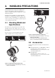
2. HANDLING PRECAUTIONS 2. HANDLING PRECAUTIONS This instrument has been inspected carefully at the factory before shipment. When the instrument is delivered, visually check that no damage has occurred during transportation. 0038 *1) Read this section carefully as it contains important information on handling this instrument. Refer to the relevant sections for information not contained in this section. If you have any problems or questions, please contact Yokogawa sales office. 2.
2. HANDLING PRECAUTIONS Explosion protected type: Explosion protect types can be installed in hazardous areas according to the types of gases for which they are certified. See the description in Chapter 8 “EXPLOSION PROTECTED TYPE INSTRUMENT” and “INSTALLATION AND OPERATING PRECAUTIONS FOR TIIS FLAMEPROOF EQUIPMENT” in this user's manual. 2.3 Storage Precautions If the instrument is to be stored for a long period of time after delivery, observe the following points.
3. INSTALLATION 3. INSTALLATION 3.1 Piping Design Precautions Based on JIS B7554 "Electromagnetic Flowmeters" and our piping condition test data, we recommend the piping conditions as shown in the following figures. When installing two or more magnetic flowmeters on a single pipe, provide a run of at least 5D between them. WARNING Installation of the magnetic flowmeter must be performed by expert engineer or skilled personnel.
3. INSTALLATION (Incorrect) Upstream side (9) Mounting Positions • Pipes must be fully filled with liquids. (Correct) Downstream side IMPORTANT It is essential that pipes remain fully filled at all times, otherwise flow rate indications may be affected and measurement errors may be caused. F0302.EPS Figure 3.1.2 Chemical Injection (5) Precautions for Use of Liquid Sealing Compounds Piping shall be designed so as to maintain the interior of the flowtube filled with fluids.
3. INSTALLATION • Mounting orientation CAUTION In order to lift a magnetic flowmeter that is fitted with eyebolts, proceed as in Figure 3.2.1. Never lift it using a bar passed through the flowtube as this damages the liner severely. IMPORTANT If electrodes are perpendicular to the ground, air bubbles near the top or precipitates at the bottom may cause measurement errors.
3. INSTALLATION (4) Terminal Box Cover (2) Inside a newly installed pipeline, there may be some foreign substances such as residue from welding or wood chips. Remove them by flushing the piping before mounting the flowmeter. This prevents the lining from being damaged, as well as the occurrence of erroneous measured signals resulting from foreign substances passing through the flowtube during measurement.
3. INSTALLATION Table 3.3.1 (2) Connecting Process Piping Weld or screw the connection fittings to the process piping. Fitting Dimensions Screw joint (process connection codes: GUR and GUN) D 0 A B C -0.1 4 (0.16) IMPORTANT • Be sure to pass the connection fittings through the union joint nuts in advance.
3. INSTALLATION Table 3.3.3 Tightening torque values for Union Joint Type and Permeable Fluids Torque (N-m / {kgf-cm} / [in-lbf]) Size mm (inch) 2.5 (0.1) 11 to 15 / {112.2 to 153} / [97.36 to 132.8] 5 (0.2) 11 to 15 / {112.2 to 153} / [97.36 to 132.8] 10 (0.4) 17 to 23 / {173.4 to 234.5} / [150.5 to 203.6] Gasket Connecting fitting Union joint nut T0304.EPS 3.3.2 *Piping *Mounting base Nominal Diameter 2.5 mm (0.1 in.) to 40 mm (1.5 in.), Wafer Type *: To be provided by user IMPORTANT F0309a.
3. INSTALLATION (3) Positioning the Flowmeter Pass two through-bolts through the adjacent holes of both flanges and position the flowmeter so that the Mini-flanges and the centering devices come in close contact with each other. Pass the other through-bolts through the other holes (refer to Figures 3.3.2 and 3.3.3). In case stud-type through-bolts are used, position them in such a way that the centering devices come in contact with the bolt threads.
3. INSTALLATION *Nut (eight units) *Through-bolt (four units) Piping-side flange *: These items can be ordered optionally. If they are provided by the user, choose nuts and bolts in compliance with the flange ratings. Centering device (two units) Mini-flange *Gasket (two units) Horizontal mounting F0311a.EPS F0311b.EPS Vertical mounting F0311c.EPS Figure 3.3.3 Table 3.3.4 Mounting Procedure for Wafer Type (size: 25 (1.0), 32 (1.25), and 40 mm (1.5 in.
3. INSTALLATION Table 3.3.5 Wafer Type Tightening Torque Values for PVC Piping Tightening torque values for PFA lining type (N-m / {kgf-cm} / [in-lbf]) Gasket types within flowtube Fluororubber gasket (optional codes GA, GC, and GD) Gasket types for user’s flange Fluororubber gasket, chloroprene rubber gasket (optional codes BSC and BCC), or the equivalent in hardness Flange ratings Size JIS 10K, ANSI Class 150, and DIN PN10 mm (inch) 1.5 to 2.5 / {15.3 to 25.49} / [13.28 to 22.13] 2.5 (0.
3. INSTALLATION 3.3.3 Nominal Diameter 50 mm (2.0 in.) to 300 mm (12.0 in.), Wafer Type (3) Positioning the Flowmeter Position the flowmeter so that the Mini-flanges and the centering devices come in close contact with each other. Be careful to prevent the four centering devices from coming into contact with the housing. If stud-type through-bolts are used, position them in such a way that the four centering devices come in contact with the bolt threads (refer to Figure 3.3.4).
3. INSTALLATION *Nut *Through-bolt Piping-side flange *Gasket (two units) *: These items can be ordered optionally. If they are provided by the user, choose nuts and bolts in compliance with the flange ratings. Housing Miniflange Horizontal mounting F0312c.EPS Centering device (four units) F0312a.EPS Vertical mounting F0312b.EPS Figure 3.3.4 Table 3.3.7 Mounting Procedure for Wafer Type (size: 50 mm (2 in.) to 300 mm (12 in.
3. INSTALLATION Table 3.3.8 Wafer Type Tightening Torque Values for PVC Piping N-m Unit: {kgf-cm} [in-lbf] Tightening torque values for PFA lining type Gasket types within flowtube Gasket types for user’s flange Fluororubber gasket (optional codes GA, GC, and GD) Fluororubber gasket, chloroprene rubber gasket (optional codes BSC and BCC), or the equivalent in hardness Flange ratings Size mm (inch) 50 (2.0) 65 (2.5) 80 (3.0) 100 (4.0) 125 (5.0) 150 (6.0) 200 (8.0) JIS 10K ANSI Class 150 9.9 to 16.
3. INSTALLATION Table 3.3.9 Wafer Type Tightening Torque Values for Metal Piping and Permeable Fluids N-m Unit: {kgf-cm} [in-lbf] Tightening torque values for PFA lining type Gasket types within flowtube Gasket types for user’s flange No gasket (standard) PTFE-sheathed non-asbestos gasket (optional codes BCF and BSF), or the equivalent in hardness Flange ratings Size mm (inch) 50 (2.0) 65 (2.5) 80 (3.0) 100 (4.0) 125 (5.0) 150 (6.0) 200 (8.0) 250 (10) 300 (12) JIS 10K ANSI Class 150 66.2 to 76.
3. INSTALLATION Table 3.3.12 Centering Device Identification (Replacement Models, PFA/Polyurethane Rubber lining) Flange ratings Size mm (inch) 10K 20K F12(75M) 150 300 PN10 PN16 50 (2.0) B B — B F — — F 80 (3.0) B F H F C — G — 100 (4.0) B F H C H — F — 150 (6.0) C D D C E — C — 200 (8.0) C D D D E C C DIN ANSI JIS — T0312-2.EPS *: Each centering device is engraved with a character as identification. Table 3.3.
3. INSTALLATION Size of Inner Diameter of Grounding ring and Outer Diameter for Effective Sealing : (2) Tightening Nuts Tighten the bolts according to the torque values for the metal piping in Table 3.3.14. For PVC piping, select an optional code of GA, GC, or GD, use rubber gaskets and tighten the nuts to the torque values for the PVC piping in Table 3.3.15.
3. INSTALLATION *Piping-side flange *Gasket (two units) *: These items must be provided by the user. Choose nuts and bolts in compliance with the flange ratings. Flowmeter-side flange *Bolt *Nut F0313.EPS Figure 3.3.5 Table 3.3.14 Mounting Procedure for Flange Type (size: 2.5 mm (0.1 in.) to 400 mm (16 in.
3. INSTALLATION Table 3.3.15 Flange Type Tightening Torque Values for PVC Piping N-m Unit: {kgf-cm} [in-lbf] Tightening torque values for PFA lining type Gasket types within flowtube Gasket types for user’s flange Fluororubber gasket (optional codes GA, GC, and GD) Fluororubber gasket, chloroprene rubber gasket, or the equivalent in hardness Flange ratings Size mm (inch) 2.5 (0.1) (with 10-mm flanges) 2.5 (0.1) (with 15-mm flanges) 5 (0.2) (with 10-mm flanges) 5 (0.2) (with 15-mm flanges) 10 (0.
3. INSTALLATION Table 3.3.16 Flange Type Tightening Torque Values for Metal Piping and Permeable Fluids N-m Unit: {kgf-cm} [in-lbf] Tightening torque values for PFA lining type Gasket types within flowtube Gasket types for user’s flange No gasket (standard) Non-asbestos gasket, PTFE-sheathed non-asbestos gasket, or the equivalent in hardness Flange ratings Size mm (inch) 2.5 (0.1) (with 10-mm flanges) 2.5 (0.1) (with 15-mm flanges) 5 (0.2) (with 10-mm flanges) 5 (0.2) (with 15-mm flanges) 10 (0.
3. INSTALLATION 3.3.5 Nominal Diameter 500 mm (20 in.) to 2600 mm (104 in.), Flange Type CAUTION • When lifting the flowtube, use the lifting rings (eye bolts or shackle). • To assure safety, keep lifting angle less than 90 degrees as shown in Figure 3.3.6 • If the size is 1600 mm (64 in.) or larger, use the eye bolts or eye nuts at all four of the locations simultaneously and lift the flowtube. Avoid lifting it from only one location or use only two locations and lift it at 45 degrees.
3. INSTALLATION Table 3.3.17 Installation Foundation Dimensions (Size 500 mm (20 in.) to 1000 mm (40 in.)). CAUTION Unit: mm(approx. inch) Location Size mm(inch) A 500 (20) 600 (24) 700 (28) 800 (32) 900 (36) 1000 (40) 350(13.8) 400(15.7) 450(17.7) 550(21.7) 700(27.6) 800(31.5) B C • Be sure to tighten the nuts according to the prescribed toeque values. Tighten them diagonally with the same torque values, step by up to the prescribed torque value.
3. INSTALLATION Table 3.3.19 Flange Type Tightening Torque Values for Material Piping Tightening torque values for Polyurethane Rubber lining (N-m / {kgf-cm} / [in-lbf]) Gasket types within Size 500 to 1000 mm: No gasket Size 1100 to 2600 mm: Butadiene-styrene-rubber+Natural rubber Gasket types for user's Rubber gasket, or the equivalent in hardness Flange ratings Size mm (inch) JIS 10K 500 (20) 43 to 72 / {438.5 to 734.2}/[380.6 to 637.2] 51 to 85 / {520.1 to 866.8}/[451.4 to 752.
3. INSTALLATION 3.3.6 Sanitary Type (2) Mounting Procedure (a) Clamp type (process connection codes: HAB, HDB, and HKB) The sanitary type can be mounted to the piping using a clamp, a union, or a welded joint. 1) Welding ferrule Weld a ferrule to the piping. NOTE IMPORTANT This section describes the remote flowtube as an example. The same procedure also applies to the integral flowmeter.
3. INSTALLATION (b) Union type (process connection codes: JDB, JKB, and JSB) 1) Welding sleeve Pass the piping through a nut and then weld a sleeve to the piping. Adapter for union connection Gasket IMPORTANT Sleeve • Be sure to weld the sleeve after passing the piping through the nut. • When welding the sleeve, pay attention to the edge preparation, level differences between the sleeve and the piping, and the welding current to avoid deforming the piping or causing stagnation of some of the fluid.
3. INSTALLATION CAUTION • In case of standard gasket (EPDM rubber), tighten the adapter mounting screw according to the torque values in Table 3.3.21. • In case that optional code GH (Silicon rubber) is selected, tighten the adapter mounting screw according to the torque values in Table 3.3.22. • Tighten the adapter mounting screw in diagonal order step by step. • After tightening of screw, confirm that gaskets protrude inside adapter. Protruding of gasket is necessary to keep the sanitary requirements.
4. WIRING 4. WIRING 4.1 Wiring the Integral Flowmeter • When waterproof glands or union equipped waterproof glands are used, avoid tightening the glands with an excessive torque. • In case of 24 V power supply version, it comes with a plug. Use this plug to cover the unused wiring port when wiring the instrument with only one, four-core cable. • Be sure to turn the power off before opening the terminal box cover. • Before turning the power on, tighten the terminal box cover securely.
4. WIRING NOTE • For power cables, always use a crimp terminal with an insulation cover. • Use crimp tools from the manufacturer of the crimp terminal you want to use to connect the crimp terminal and cable. • Use crimp tools that are appropriate for the diameter of the cable to be connected. 4.1.3 Washer Gasket Waterproof gland Wiring Ports Cable This instrument is of watertight construction as stipulated in JIS C0920.
4. WIRING - DIO + - D + - I POWE SUPPLY (2) Terminal Configuration When the cover is removed, the connection terminals will be visible. + L/+ N/ - (3) Conduit Wiring When wiring the conduits, pass the conduit through the wiring connection port, and utilize the waterproof gland to prevent water from flowing in. Place the conduit pipe on an angle as shown in Figure 4.1.4. Install a drain valve at the low end of the vertical pipe, and open the valve regularly. Drain valve F0406.EPS Figure 4.1.
4. WIRING 2) • Install an external switch or circuit breaker as a means to turn the power off (capacitance; 15A, conforming to IEC947-1 and IEC947-3). Locate this switch either near the instrument or in other places facilitating easy operation. Affix a “Power Off Equipment” label to this external switch or circuit breaker.
4. WIRING For explosion proof type except TIIS, follow the domestic electrical requirements as regulated in each country. 600 V vinyl-insulated cable (2 mm2 or larger) IMPORTANT When optional code A (lighting protector) is selected, the ground should satisfy Class C requirements (grounding resistance, 10 or less). grounding ring • Class D requirements (ground resistance, 100 or less). Optional code A (lighting protector): Class C requirements (ground resistance, 10 or less).
4. WIRING • To avoid communication (BRAIN/ HART) failure, it is recommended to use the shield cable. Connect the AXF integral flowmeter terminal to external instruments, giving attention to the following points. For FOUNDATION Fieldbus protocol, please refer to IM 01E20F02-01E. For PROFIBUS PA protocol, please refer to IM 01E20F12-01E. NOTE For pulse output from the DO terminals, parameters must be set.
4. WIRING Status Input Protective diode AXF integral flowmeter DO+ (or DIO+) IMPORTANT Load DO- (or DIO-) Status inputs are designed for use with novoltage (dry) contacts. Be careful not to connect the status to any signal source carrying voltage. Applying voltage may damage the input circuit. This connection is not possible. AXF integral flowmeter DO+ (or DIO+) Relay Electromagnetic valve DO- (or DIO-) External power supply 30V DC, 0.2A.
4. WIRING 4.2 Wiring the Remote Flowtube • Ground the remote flowtube and the converter separately. • Cover each shield of the signal cable with vinyl tube or vinyl tape to avoid contact between two shields or between a shield and a case. • When waterproof glands or union equipped waterproof glands are used, avoid tightening the glands with an excessive torque. • Be sure to turn the power off before opening the terminal box cover. • Before turning the power on, tighten the terminal box cover securely.
4. WIRING 4.2.2 Cables CAUTION (1) Dedicated Signal Cable (AXFC) • As crimp terminals A, B, SA, SB and C have their own electrical potentials, securely insulate them so as not to come in contact with one another. • To prevent a shield from coming in contact with another shield or the case, cover each shield with a vinyl tube or wrap it in vinyl tape. Conductors (A and B) Shields (SA and SB) Tape Outer jacket 10.5 (0.413") Shield (C) Insulation Insulation Figure 4.2.1 NOTE F0417.
4. WIRING 4.2.3 Unit : mm (approx. inch) This instrument is of watertight construction as stipulated in JIS C0920. It is shipped with a wiring bracket (waterproof gland or waterproof gland with union) or a plastic gland attached, only in cases where an optional specification is selected for the wiring port. In case of the explosion proof type, refer to chapter 8. EX2 EX1 EX2 EX1 Crimp terminal 85 (3.35) Wiring Ports 85 (3.
4. WIRING 4.2.4 Wiring Connections WARNING Before wiring, be sure that the power supply for AXFA11 or AXFA14 converter has been turned off to prevent an electrical shock. Gasket PF1/2 Washer (1) Removing Cover (Size 2.5 to 1000 mm (0.1 to 40 in.)) Loosen the cover locking screw clockwise using a hexagonal wrench (nominal size 3) to unlock the cover. (Upon shipment from the manufacturing plant, the cover is unlocked.
4. WIRING Terminal Symbols A B C EX1 EX2 (3) Wiring the Remote Flowtube (GeneralPurpose Use, Submersible Type, Sanitary Type, Size 2.5 to 400 mm (0.1 to 16 in.)) with Converters Description Flow signal output 1) Connection with the AXFA11 converter Connect wiring as shown in the figure below.
4. WIRING (4) Wiring the Remote Flowtube (Explosion Proof Type) with Converters 2) Connection with the AXFA14 converter In case of explosion proof type for ATEX, FM, CSA, IECEx and TIIS certification, connect wiring as shown in the figure below. IMPORTANT In case of the explosion proof type, the protective grounding of remote flowtube must be connected to a suitable IS grounding system. In that case, (functional grounding terminal) need not be connected.
4. WIRING (5) Wiring the Remote Flowtube (GeneralPurpose Use, Submersible Type, Size 500 to 1000 mm (20 to 40 in.)) with Converters IMPORTANT A remote flowtube (size 1100 to 2600 mm) cannot be combined with AXFA14 converter. 1) Connection with the AXFA11 converter Connect wiring as shown in the figure below. (7) Grounding I+ I– CURRENT OUT 4-20mA out SO1+ SO2+ COM STATUS OUT AL+ AL– ALARM OUT C SA A SIGNAL B SB AXFA11 converter FUSE 2.
4. WIRING (8) Installing the Cover (Size 2.5 to 1000 mm (0.1 to 40 in.)) Install the cover to the flowtube by turning it in the direction of the arrow as shown below. Tighten the cover locking screw counterclockwise using a hexagonal wrench (nominal size 3) to lock the cover. The electromotive force of the magnetic flowmeter is minute and it is easy to be affected by noise. And also that reference electric potential is the same as the measuring fluid potential.
5. MAINTENANCE 5. MAINTENANCE WARNING • Maintenance work must be carried out by the trained personnel having knowledge of safety standard and not by operators. • When opening the cover, wait for more than 10 minutes after turning off the power. Furthermore, opening of the cover must also be carried out by the trained personnel having knowledge of safety standard.
5. MAINTENANCE 5.2 Removing, Cleaning, and Installing Replaceable Electrodes (General-Purpose Use Type Only) 5.2.1 (4) Using end A of the tool, open the electrode cover. End A End B Removing Replaceable Electrodes (1) The following tools are required to replace the electrodes: • Special tool for removing and installing electrodes (F9807SK): Optional • Torque wrench or torque driver (nominal size 12) • Phillips screwdriver F0504.
5. MAINTENANCE 5.2.2 (6) Move aside the electrode lead wire and avoiding the screw, insert end A of the tool to the electrode and loosen the electrode holder using the torque driver. Cleaning Replaceable Electrodes (1) Clean the electrode surface (wetted part) with alcohol or other cleaning agents. O-ring Electrode surface Electrode holde End A Torque driver F0506.EPS (7) Screw end B of the tool into the screw block of the electrode, and pull the tool straight out to remove the electrode holder.
5. MAINTENANCE 5.2.3 Installing Replaceable Electrodes (2) Using end A of the tool, tighten the electrode holder. NOTE It is recommended to replace the O-ring when reinstalling the replaceable electrode. Use the Oring specified by Yokogawa (G9303SE: material is fluororubber). NOTE Precautions for storage of O-rings: • Keep them in a cool, dark place. • Wrap them well. • Do not use O-rings after one year since their purchase. Torque driver F0511.
5. MAINTENANCE 2) Installing the butt weld adapter NOTE Install a gasket to fit in the groove of the butt weld adapter, and tighten in the adapter with the mounting screws. Always hold down the lead wire and terminal lug when adjusting the mounting screw. (5) Put the lead wire in the electrode boss, and install the electrode cover to the boss and tighten it using end A of the tool. Mini-flange Gasket Butt weld adapter Adapter mounting screw Electrode boss F0316.EPS Figure 5.3.
5. MAINTENANCE CAUTION • The lining of sanitary type uses fluorocarbon PFA. For the property of fluorocarbon PFA, it is possible that the adapter mounting screws may loosen as time passes, so retighten them regularly. • Be sure to retighten the adapter mounting screws according to the prescribed torque values in Table 5.3.1 or Table 5.3.2. Retighten them diagonally with the same torque values, step by step up to the prescribed torque value.
5. MAINTENANCE 5.4.2 5.4 Maintenance for Converter (Integral Flowmeter Only) Changing the Direction of the Display Unit 5.4.2.1 Removing the Cover (1) Turn off the power. (2) Loosen cover locking screw 1 clockwise using a hexagonal wrench (nominal size 3) to unlock the cover. (Upon shipment from the manufacturing plant, the cover is locked.) Hold the flowmeter with your hand and remove the cover by turning it in the direction of the arrow as shown below.
5. MAINTENANCE 5.5 Setting of Switches (Integral Flowmeter Only) *1 IMPORTANT • Removing and installing cover are necessary for setting switches. Perform removing and installing of the cover as described in section 5.4.2.1 and 5.4.2.3. • To preserve the safety, do not touch the electrical circuit and the cables except setting switches. Display unit mounting screws (two screws) Clockwise 90° F0518-1.EPS Changing the Display Unit Direction 90 Degrees Figure 5.4.2 5.5.
5. MAINTENANCE Low Switch 1 Switch 2 Enable 5.6 Regular Inspection Items High 2 ← Burnout setting switch 1 ← Write protect setting switch Protect (1) Inspection of moisture-proofing inside the terminal box: Once/year (2) Retightening of piping joint screws: About twice/year (3) Inspection of electrodes and lining (in case of adhesive and/or abrasive fluids, etc.) Determine the period of regular inspection as necessary. 5.7 Excitation Coil and Insulation Resistance Check (Remote Flowtube Only) F0520.
5. MAINTENANCE Coil Circuit Checking is possible even if the pipe is filled with fluid. Test Terminals Test Voltage Specification Between terminals EX1 and C 500 V DC (Use an insulation tester or the equivalent.) 1 M or more T050601.EPS Signal Circuit Before testing, be sure to empty and dry the interior of the pipe, checking that there is no adhesive material. Also undo the wiring connection on the converter side before testing.
5. MAINTENANCE 5.8 Troubleshooting Although magnetic flowmeters rarely require maintenance, failures may occur when the instrument is not operated correctly. This section describes troubleshooting procedures where the cause of the breakdown is identified through receiver indication. 5.8.1 No Indication START Is an error being displayed? Check the converter display.
5. MAINTENANCE 5.8.2 Unstable Zero START Investigate whether or not the flowtube is filled with fluid and that it is free of bubbles. *1: When checking for bubbles, it is convenient if there is a gas vent hole on the flowtube’s downstream side. *1 Is the flowtube completely full of fluid? Particular care must be taken in the case of horizontal mounting. In order to ensure complete filling of the tube, either adjust the mounting position or switch to vertical mounting.
5. MAINTENANCE 5.8.3 Disagreement Between Indication and Actual Flow START NO Are parameters set correctly? Set the parameters correctly. YES Examine the condition of the fluid in the flowtube, of bubbles, and of grounding. Was zero adjustment carried out correctly? Execute zero adjustment when the flowtube is filled completely with fluid and when the fluid is not moving.
6. OUTLINE 6. OUTLINE ■ STANDARD SPECIFICATIONS HART: Load Resistance: 250 to 600Ω (including cable resistance) Refer to IM 01E20F02-01E for FOUNDATION Fieldbus communication type and IM 01E20F12-01E for PROFIBUS PA communication type marked with “ ” Note: HART is a registered trademark of the HART Communication Foundation. Converter (Integral flowmeter) Data Security During Power Failure: Data (parameters, totalizer value, etc.) storage by EEPROM. No back-up battery required.
6. OUTLINE Functions Multi-range Function (*1)(*2): • Range switching via status input Status input enables the switching of up to two ranges. • Automatic range switching When the flow rate exceeds 100 % of the range, transition to the next range (up to four ranges) is carried out automatically. Range swiching can be confirmed by status outputs and indicator. How to Set Parameters (*2): The indicator’s LCD and three infra-red switches enable users to set parameters without opening the case cover.
6. OUTLINE Flowtubes (Remote Flowtube/Integral Flowmeter) Size of AXF Flowtubes: AXF Standard (Lay length code 1) Unit: mm (in.) Use Process Connection Lining PFA Remote Flowtube Integral Flowmeter 2.5 (0.1), 5 (0.2), 10 (0.4), 15 (0.5), 25 (1.0), 32 (1.25), 40 (1.5), 50 (2.0), 65 (2.5), 80 (3.0), 100 (4.0), 125 (5.0), 150 (6.0), 200 (8.0), 250 (10), 300 (12) 25 (1.0), 32 (1.25), 40 (1.5), 50 (2.0), Polyurethane 65 (2.5), 80 (3.0), 100 (4.0), 125 (5.0), Rubber 150 (6.0), 200 (8.
6. OUTLINE Size of AXF Flowtubes: AXF Standard (Lay length code 1) (continued) Unit: mm (in.) Use Process Connection Lining PFA Wafer Submersible Type Flange Remote Flowtube Integral Flowmeter 15 (0.5), 25 (1.0), 32 (1.25), 40 (1.5) 50 (2.0), 65 (2.5), 80 (3.0), 100 (4.0), 125 (5.0), 150 (6.0), 200 (8.0), 250 (10), 300 (12) — Union Joint Clamp: Tri-Clamp (*4), DIN32676 ISO2852/SMS3016 Union: Sanitary Type DIN11851 ISO2853 (*5) SMS1145 (*6) Butt Weld: DIN11850, ISO203 25 (1.0), 32 (1.25), 40 (1.
6. OUTLINE Size of AXF Flowtubes: Replacement model for earlier ADMAG or ADMAG AE (Lay length code 2) Unit: mm (in.) Use Process Connection Lining — 25 (1.0), 40 (1.5), 50 (2.0), 80 (3.0), Polyurethane 100(4.0), 150 (6.0), 200(8.0) rubber — Wafer (*6) Flange (*7) Wafer (*6) Submersible Type 150 (6.0), 200 (8.0), 250 (10) PFA Polyurethane 150 (6.0), 200 (8.0), 250 (10) rubber 15 (0.5), 25 (1.0), 40 (1.5), 50 (2.0), — PFA 80 (3.0), 100 (4.0), 150 (6.0), 200 (8.
6. OUTLINE Submersible Type: Non-tar epoxy coating (black) Size 25 mm (1.0 in.) to 125 mm (5.0 in.) Flowtube Material: Part Name Material Housing Stainless steel-JIS SUS304 (AISI 304 SS/EN 1.4301 equivalent) Size 2.5 mm (0.1 in.) to 15 mm (0.5 in.) MiniFlange Part Name Material Housing Stainless steel-JIS SCS11 equivalent Flange Stainless steel-JIS SUS304 or SUSF304 (AISI 304 SS/EN 1.4301 equivalent) Wafer Type PFA/Polyurethane Rubber lining Stainless steel-JIS SCS13 (EN 1.
6. OUTLINE Size 150 mm (6.0 in.) to 400 mm (16 in.) Flange Part Name Material Housing Carbon steel-JIS SPCC equivalent Stainless steel-JIS SUS304 or SUSF304 (AISI 304 SS/EN 1.4301 equivalent) Carbon steel-JIS SS400 or SFVC 2A Process Connection code: B** Process Connection code: C** Grounding Ring/Grounding Electrode: • Grounding Ring(plate type) Stainless steel-JIS SUS316 (AISI 316 SS/EN 1.4401 equivalent), Stainless steel-JIS SUS316L (AISI 316L SS/EN 1.
6.
6. OUTLINE ■ HAZARDOUS AREA CLASSIFICATION Natural Soft Rubber, EPDM Rubber lining: Internal insertion type Ceramics lining: Integral type Sanitary Type: Internal insertion type Refer to Chapter 8. ■ STANDARD PERFORMANCE Replaceable Electrode Type Electrode parts can be put into unit to facilitate replacement or mounting at customer site. The optional dedicated tool (F9807SK) is required.
6. OUTLINE Polyurethane Rubber /Natural Soft Rubber / EPDM Rubber Lining: Size mm (in.) Flow Velocity V m/s (ft/s) V 0.3 (1.0) 25 (1.0) to 400 (16) Size 2200 mm (88 in.) to 2600 mm (104 in.) % of Rate 2.4 Standard Accuracy (Calibration code B) 2.0 1.6 1.0 mm/s 0.3 ! V ! 10 0.35% of Rate (1.0) (33) V 0.3 (1.0) 1.75 mm/s 0 0.3 ! V 1 0.25% of Rate 1 mm/s (1.0) (3.3) 500 (20) to 1000 (40) 0 0.3 ! V 1 0.4% of Rate 1 mm/s (1.0) (3.3) 2200 (88) to 2600 (104) V 1 (3.3) T09.
6. OUTLINE ■ NORMAL OPERATING CONDITIONS CAUTION Ambient Temperature: –40° to +60°C (–40° to +140°F) *1: When performing the Insulation Resistance Test or the Withstand Voltage Test, please obey the following caution. • Following the relevant test, wait for more than 10 seconds after the power supply has been turned off before removing the cover. • Remove all wires from terminals before testing.
6. OUTLINE Cable Length and Liquid Conductivity (Remote Flowtube): Measurable Flow Rate Range: SI Units (Size: mm, Flow rate: m3/h) Size (mm) Size 2.5 to 10 mm (0.1 to 0.4 in.) Cable length m (ft) Add 1% of Rate to the accuracy shown in accuracy description As show in accuracy description 2.5 5 100 (330) Combined with AXFA11 or AXFA14 converter 50 (170) 3 (10) 0 (0) 1 5 10 20 Liquid conductivity 50 (µS/cm) Size 15 to 125 mm (0.5 to 5.0 in.
6. OUTLINE English Units (Size: in., Flow rate: GPM) 0 to Min. Span Flow Rate (0.33ft/s) 0 to Max. Span Flow Rate (33ft/s) 0.1 0 to 0.0078 GPM 0 to 0.7780 GPM 0.2 0 to 0.0312 0 to 3.112 Size (in.) 0.4 0 to 0.1245 0 to 12.44 0.5 0 to 0.1946 0 to 19.45 1.0 0 to 0.7781 0 to 77.80 1.25 0 to 1.216 0 to 121.5 1.5 0 to 1.751 0 to 175.0 2.0 0 to 3.113 0 to 311.2 2.5 0 to 4.863 0 to 486.2 3.0 0 to 7.003 0 to 700.
6. OUTLINE General-Purpose Use, Remote Flowtube (electrode structure code 2: replaceable electrode) General-Purpose Use and Explosion proof Type, Integral flowmeter (electrode structure code 1: Nonreplaceable electrode) 25 to 200 mm (1.0 to 8.0 in.) (flange type, wafer type) 250, 300 mm (10, 12 in.) (flange type) Pressure MPa (psi) 350, 400 mm (14 to 16 in.) (flange type) 250, 300 mm (10, 12 in.) (wafer type) Pressure MPa (psi) 2.5 to 50 mm (0.1 to 2.0 in.) 80 to 200 mm (3.0 to 8.0 in.) 4 (580) 3.
6. OUTLINE Natural Soft Rubber Lining Reasonable Figure for Thermal Shock of Creamics Lining: General-Purpose Use and Submersible Type, Remote Flowtube (electrode structure code 1: Non-replaceable electrode) Size 2.5 to 25 mm (0.1 to 1.0 in.) ∆T°C(°F) 120 (248) 50 mm (2.0 in.) (flange type, wafer type) Increase 100 (212) 65 to 200 mm (2.5 to 8.0 in.) (flange type, wafer type) 250, 300 mm (10, 12 in.) (flange type) Pressure MPa (psi) 250, 300 mm (10, 12 in.) (wafer type) 350, 400 mm (14 , 16 in.
6. OUTLINE Remote Flowtube ■ ACCESSORIES Remote Flowtube (size 2.5 to 1000 mm(0.1 to 40 in.)): Centering device (wafer type only): 1 pc. Hexagonal wrench: 2 pcs. Terminal configuration EX2 A A B B EX2 EX1 (Only for Explosion proof type) C EX1 Integral Flowmeter “ ” B EX2 EX1 Terminal configuration C size 2.5 to 400 mm (0.1 to 16 in.) B ■ TERMINAL CONFIGURATION AND TERMINAL WIRING + L/+ N/ - A A EX2 size 500 to 1000 mm (20 to 40 in.) size 1100 to 2600 mm (44 to 104 in.
6.
6. OUTLINE *1: For a wafer type of 2.5 to 10 mm (0.1 to 0.4 in.), prepare 15 mm (0.5 in.) diameter nominal flanges on the process pipe side. (Process connection codes: AA1, AA2, AD4, AJ1, and AJ2) *2: Even when DIN PN10 or 16 is required for a model of size 2.5 to 50 mm (0.1 to 2.0 in.), select PN40 (Process connection code: AD4) because there is no difference in the dimensions of the mating faces. Even when DIN PN10 is required for a model of size 65 to 150 mm (2.5 to 6.0 in.
6. OUTLINE AXF STANDARD (Wafer /Union Joint Type) General-purpose Use/Explosion proof Type, Ceramics Lining Model AXF002 AXF005 AXF010 AXF015 AXF025 AXF040 AXF050 AXF080 AXF100 AXF150 AXF200 Use Suffix Code ····················· ····················· ····················· ····················· ····················· ····················· ····················· ····················· ····················· ····················· ····················· Size 2.5 mm (0.1 in.) Size 5 mm (0.2 in.) Size 10 mm (0.
6. OUTLINE *1: Even when DIN PN10 or 16 is required for a model of size 2.5 to 50 mm (0.1 to 2.0 in.), select PN40 (Process connection code : AD4) because there is no difference in the dimensions of the mating faces. Even when DIN PN10 is required for a model of size 65 to 150 mm (2.5 to 6.0 in.), select PN16 (Process connection code : AD2) because there is no difference in the dimensions of the mating faces. *2: Mating dimensions are based on standards as follow: 1 2 N ANSI:ASME B 16.
6. OUTLINE AXF STANDARD (Flange Type) Size 2.5 mm (0.1 in.) to 400 mm (16 in.
6. OUTLINE *1: For a flange type of 2.5 to 10 mm (0.1 to 0.4 in.), prepare 15 mm (0.5 in.) diameter nominal flanges on the process pipe side. (Process connection codes: BA1, BA2, BD4, BJ1, and BJ2) *2: Even when DIN PN10 or 16 is required for a model of size 2.5 to 50 mm (0.1 to 2.0 in.), select PN40 (Process connection codes: BD4,CD4 and DD4) because there is no difference in the dimensions of the mating faces. Even when DIN PN10 is required for a model of size 65 to 150 mm (2.5 to 6.0 in.
6. OUTLINE AXF STANDARD (Flange Type) Size 500 mm (20 in.) to 2600 mm (104 in.
6.
6. OUTLINE REPLACEMENT MODEL FOR EARLIER ADMAG OR ADMAG AE (Wafer Type) General-purpose Use/Submersible Type/Explosion proof Type, PFA/Polyurethane Rubber Lining For the Wafer Types of size 250 mm (10 in.), 300 mm (12 in.), AXF Standard shall be selected. Model Suffix Code Use Size 2.5 mm (0.1 in.) Size 5 mm (0.2 in.) Size 10 mm (0.4 in.) Size 15 mm (0.5 in.) Size 25 mm (1.0 in.) Size 40 mm (1.5 in.) Size 50 mm (2.0 in.) Size 80 mm (3.0 in.) Size 100 mm (4.0 in.) Size 150 mm (6.0 in.) Size 200 mm (8.
6. OUTLINE *1: For a wafer type of 2.5 to 10 mm (0.1 to 0.4 in.), prepare 15 mm (0.5 in.) diameter nominal flanges on the process pipe side. (Process connection codes: AA1, AA2, AD4, AJ1, and AJ2) *2: Even when DIN PN10 or 16 is required for a model of size 2.5 to 50 mm (0.1 to 2.0 in.), select PN40 (Process connection code: AD4) because there is no difference in the dimensions of the mating faces. Even when DIN PN10 is required for a model of size 65 to 150 mm (2.5 to 6.0 in.
6. OUTLINE REPLACEMENT MODEL FOR EARLIER ADMAG OR ADMAG AE (Flange Type) General-purpose Use/Submersible Type/Explosion proof Type, PFA/Polyurethane Rubber Lining For Flange Types of size 15 mm (0.5 in.) to 100 mm (4.0 in.), 300 mm (12 in.) to 2600 mm (104 in.), AXF Standard shall be selected. Model AXF150 AXF200 AXF250 Use Suffix Code Description · · · · · · · · · · · · · · · · · · · · Size 150 mm (6.0 in.) Integral Flowmeter/Remote Flowtube · · · · · · · · · · · · · · · · · · · · Size 200 mm (8.0 in.
6. OUTLINE *1: Even when DIN PN10 is required for a 150 (6.0 in.)-mm model, select PN16 (Process connection code: CD2) because there is no difference in the dimensions of the mating faces. *2: Mating dimensions are based on standards as follow: ANSI: ASME B 16.5, DIN:DIN 2501, JIS:JIS B 2220 and JIS G 3443-2 *3: N shall be always selected for remote flowtubes.
6. OUTLINE ■ OPTIONAL SPECIFICATIONS FOR FLOWTUBES Table of Optional Specifications (Size 2.5 mm (0.1 in.) to 400 mm (16 in.
6. OUTLINE Table of Optional Specifications (Size 2.5 mm (0.1 in.) to 400 mm (16 in.)) (continued) : Available –: Not available Applicable Model N AXF***H- P Waterproof glands are attached to the electrical connections. Available D E AXF***H- F G Waterproof Glands N AXF***W- P electrical connections. Available only for JIS G1/2 female electric connections.
6. OUTLINE Table of Optional Specifications (Size 2.5 mm (0.1 in.) to 400 mm (16 in.
6. OUTLINE Table of Optional Specifications (Size 2.5 mm (0.1 in.) to 400 mm (16 in.)) (continued) : Available –: Not available Applicable Model certificate (QIC) is submitted.
6. OUTLINE Table of Optional Specifications (Size 500 mm (20 in.) to 2600 mm (104 in.)) : Available –: Not available Applicable Model Specifications Submersible Remote Flowtube Remote Flowtube AXF***W-N Code AXF***G-N Item General – DHC Available for the submersible type and a model with optional code DHC. The cable length is limited up to 200 meters when combined with an AXFA11 converter. Following “L,” specify the cable length in three digits as a multiple of 1 meter (e. g.
6. OUTLINE Table of Optional Specifications (Size 500 mm (20 in.) to 2600 mm (104 in.)) (continued) : Available –: Not available Applicable Model Specifications Calibration Certificate Remote Flowtube Code AXF***W-N Hydrostatic Test Submersible Remote Flowtube AXF***G-N Item General The test verifies the absence of leaks by applying the following water pressures (which are determined under process connection conditions) to lining for ten minutes.
6. OUTLINE ■ EXTERNAL DIMENSIONS AXF Standard, AXF002-AXF015, Wafer Type, PFA Lining Unit : mm (approx. inch) Integral Flowmeter Remote Flowtube 51.5 51.5 (2.03) (2.03) 111(4.37) Hr 70(2.76) 1 A Hi 73(2.87) 49(1.93) 1 66*1 (2.6) Remote Flowtube Ground Terminal (M4) 28(1.1) ø128(5.04) 154(6.06) D E 1 F 2 A G N N P 197(7.76)*1 Ground Terminal (M4) ø86(3.38) (1.89) 48 *4 AXF002 G AXF005 W AXF010 C AXF015 Integral Flowmeter ) (ød 3(0.12) D H1 63.5(2.
6. OUTLINE AXF Standard, AXF150-AXF300, Wafer Type, PFA /Polyurethane Rubber /Natural Soft Rubber /EPDM Rubber Lining Unit : mm (approx. inch) Integral Flowmeter Remote Flowtube 154(6.06) 111(4.37) (ø d) Hi *5: D, E, F, G; Integral Flowmeter, N, P; Remote Flowtube 51.5 51.5 (2.03) (2.03) (1.89) ø128(5.04) 1 A 66*1 (2.6) Ground Terminal (M4) 28(1.1) 70(2.76) 1 2 73(2.87) 49(1.93) AXF150 G AXF200 W AXF250 C AXF300 48 Remote Flowtube 197(7.76)*1 Ground Terminal (M4) ø86(3.
6. OUTLINE AXF Standard, AXF015, Wafer Type, Ceramics Lining Unit : mm (approx. inch) Integral Flowmeter Remote Flowtube 1 (ød H1 63.5(2.50) *3: D, E, F, G; Integral Flowmeter, N, P; Remote Flowtube L*2 * No infra-red switches are furnished for Fieldbus communication type. Model Size code 015 Size 15(0.5) Lining code Remote flowtube 2 L* 85(3.35) D 44(1.73) ød 15(0.59) Height H1 144(5.67) Max. Height Hr 268(10.55) Hi Integral Max. Height flowmeter Weight kg (lb) 306(12.
6. OUTLINE AXF Standard, AXF150, AXF200, Wafer Type, Ceramics Lining Unit : mm (approx. inch) *3 Remote Flowtube 1 A Ground Terminal (M4) *3: D, E, F, G; Integral Flowmeter, N, P; Remote Flowtube ø86 (3.38) 154(6.06) 197(7.76)*1 66*1 51.5 51.5 (2.6) (2.03) (2.03) 111(4.37) Hr Hi 28(1.1) (1.89) 70(2.76) 73 49 (2.87) (1.93) 48 Integral Flowmeter Remote Flowtube Ground Terminal (M4) ø128(5.
6. OUTLINE AXF Standard, AXF002-AXF015, JIS/ANSI/DIN Flange Type, PFA Lininig Unit : mm (approx. inch) Integral Flowmeter 111(4.37) (1.89) 48 t *2 N-øh Hr *4: D, E, F, G; Integral Flowmeter, N, P; Remote Flowtube 28(1.1) 66*1 51.5 51.5 (2.6) (2.03) (2.03) ø128(5.04) 1 Ground Terminal (M4) ø86(3.38) 154(6.06) Remote Flowtube Ground Terminal (M4) 197(7.76)*1 70(2.
6. OUTLINE AXF Standard, AXF025-AXF050, JIS/ANSI/DIN Flange Type, PFA /Polyurethane Rubber /Natural Soft Rubber /EPDM Rubber Lining Unit : mm (approx. inch) Integral Flowmeter 51.5 51.5 28(1.1) (2.03) (2.03) 111(4.37) 70(2.76) t *2 N-øh ) (ød H1 *4: D, E, F, G; Integral Flowmeter, N, P; Remote Flowtube 66*1 (2.6) (1.89) ø128(5.04) 48 Hr 1 2 Ground Terminal (M4) 197(7.76)*1 (H2) D A E 1 U F 2 D G N G N P AXF025 G AXF032 W AXF040 C AXF050 154(6.
6. OUTLINE AXF Standard, AXF065-AXF125, JIS/ANSI/DIN Flange Type, PFA /Polyurethane Rubber /Natural Soft Rubber /EPDM Rubber Lining Unit : mm (approx. inch) Integral Flowmeter Remote Flowtube Integral Flowmeter Remote Flowtube Ground Terminal (M4) Ground Terminal (M4) 154(6.06) Hr 2 1 *4: D, E, F, G; Integral Flowmeter, N, P; Remote Flowtube Process Connection BJ2/CJ2(JIS20K) Size code 065 080 100 125 065 080 Size Lining code 65 (2.5) A,U D,G 200 (7.87) 175 (6.89) 22 (0.87) 66 (2.
6. OUTLINE AXF Standard, AXF150, AXF200, JIS/ANSI/DIN Flange Type, PFA /Polyurethane Rubber /Natural Soft Rubber /EPDM Rubber Lining B B D A B E 1 G AXF150 U 1 B F 2 W AXF200 D 2 C G N C G C N C P *4: D, E, F, G; Integral Flowmeter, C *4 N, P; Unit : mm (approx. inch) A D J G 1 1 A D J G 1 Remote Flowtube Integral Flowmeter Integral Flowmeter Remote Flowtube Ground Terminal (M4) 197(7.76)*1 Ground Terminal (M4) ø86 (3.38) 154(6.06) 48 66*1 51.5 51.5 111(4.37) ø128(5.
6. OUTLINE AXF Standard, AXF250-AXF400, JIS/ANSI/DIN Flange Type, PFA /Polyurethane Rubber /Natural Soft Rubber /EPDM Rubber Lining *4 AXF250 G AXF300 W AXF350 C AXF400 D A E 1 U F 2 D G N G N P 1 2 *4: D, E, F, G; Integral Flowmeter, N, P; Remote Flowtube B B B B C C C C A D J G 1 1 A D J G 1 Integral Flowmeter Unit : mm (approx. inch) Integral Flowmeter Ground Termonal (M4) Remote Flowtube 154(6.06) ø86 Ground Terminal (M4) 197(7.76)*1 (3.38) 66*1 51.5 51.5 (2.76) 28(1.1) (2.6) (2.
6. OUTLINE AXF Standard, AXF015-AXF125, Sanitary for Clamp Connection, PFA Lining Unit : mm (approx. inch) Integral Flowmeter 154(6.06) øD L HAB / HDB / HKB Size code 015 025 032 040 050 065 080 100 125 Size 15 (0.5) 25 (1) 32 (1.3) 40 (1.5) 50 (2) 65 (2.6) 80 (3) 100 (4) 125 (5) A A A HAB Integral Inner dia. ød HDB Flowmeter HKB Process Connection Nominal Size Height H1 Max. Height Hr 2 Weight kg (lb)* Max. Height Weight kg (lb) A A A 216 (8.52) 129 (5.08) 72.
6. OUTLINE AXF Standard, AXF015-AXF125, Sanitary for Union Connection, PFA Lining Unit : mm (approx. inch) Integral Flowmeter 197(7.76)*1 66*1 51.5 51.5 (2.6) (2.03) (2.03) 28(1.1) 111(4.37) 70 (2.76) Hr Hi J K B J D B 1 J S B 73 49 (2.87) (1.93) D E 1 F 2 A L 1 N G N N P Ground Terminal (M4) Ground Terminal (M4) ø86(3.38) 48 (1.89) 154(6.06) *3 Integral Flowmeter Remote Flowtube ø128(5.
6. OUTLINE AXF Standard, AXF015-AXF125, Sanitary for Butt Weld, PFA Lining Unit : mm (approx. inch) Integral Flowmeter 70(2.76) øD 032 040 050 065 080 100 125 Size 25 (1) 32 (1.3) 40 (1.5) 50 (2) 65 (2.6) 80 (3) 100 (4) 125 (5) Lining code L Outside dia. øD Inner dia. ød KKB KDB Integral Flowmeter Height H1 Max. Height Hr 2 Weight kg (lb)* Max. Height Process Connection Nominal Size Hi Weight kg (lb) A A A A A A A A A 126 (4.98) 73 (2.87) 15.2 (0.60) 16 (0.
6. OUTLINE Replacement model for Earlier ADMAG or ADMAG AE, AXF002-AXF015, Wafer Type, PFA Lining Unit : mm (approx. inch) Integral Flowmeter Remote Flowtube 154(6.06) 51.5 51.5 (2.03) (2.03) 66*1 (2.6) 111(4.37) 70(2.76) 2 A Ground Terminal (M4) 28(1.1) Hr ) (ød 63.5 (2.50) 3(0.12) H1 *4: D, E, F, G; Integral Flowmeter, N, P; Remote Flowtube D 1 Hi 73(2.87) 49(1.93) AXF002 G AXF005 W AXF010 C AXF015 Remote Flowtube 197(7.76)*1 ø128(5.04) Ground Terminal (M4) ø86(3.38) (1.
6. OUTLINE Replacement model for Earlier ADMAG or ADMAG AE, AXF150, AXF200, Wafer Type, PFA /Polyurethane Rubber Lining Unit : mm (approx. inch) Integral Flowmeter Remote Flowtube ø86(3.38) *4 66*1 51.5 51.5 (2.6) (2.03) (2.03) 28(1.1) 111(4.37) ø128(5.04) d) (ø *4: D, E, F, G; Integral Flowmeter, N, P; Remote Flowtube 70(2.76) 2 A Hr 1 73(2.87) 49(1.93) 48(1.89) D E 1 A F 2 U G N N P Hi G AXF150 W AXF200 C Remote Flowtube Ground Terminal (M4) 197(7.
6. OUTLINE Replacement model for Earlier ADMAG or ADMAG AE, AXF150-AXF250, JIS/ANSI/DIN Flange Type, PFA /Polyurethane Rubber Lining *4 AXF150 G AXF200 W AXF250 C D E 1 A F 2 U G N N P 1 2 *4: D, E, F, G; Integral Flowmeter, N, P; Remote Flowtube A D 2 J G 1 C C C C Integral Flowmeter Integral Flowmeter Ground Terminal (M4) 197(7.76)*1 Remote Flowtube 154(6.06) ø86 Ground Terminal (M4) (3.38) 66*1 51.5 51.5 (2.6) (2.03) (2.03) 70 (2.76) øD Hr (H2) øC ) (ød H1 H3 Hi 111(4.
6. OUTLINE AXF Standard, AXF500-AXF10L, JIS/ANSI/DIN Flange Type, Polyurethane Rubber Lining AXF500 AXF600 AXF700 G AXF800 W AXF900 AXF10L Unit : mm (approx. inch) CJ1 CG1 1 CA1 CD1 NNUL 1S Graund Terminal (M4) ø86(3.38) t 15(0.59) 111(4.37) 48(1.89) ø40(1.57) θ° (H2) N- øh øD Hr øC (ø d) H1 Flange Detail 4- ø24(0.94) (Anchor bolt M20) 125 (4.92) 35 (1.
6. OUTLINE AXF Standard, AXF11L-AXF13L, JIS Flange Type, Polyurethane Rubber Lining AXF11L G AXF12L W AXF13L Unit : mm (approx. inch) NNUL 1S CG11 CG1(JIS F12) Process Connection A Size code Model θ˚ 11L 1100 (44) U Size Shackle B Lining code N-øh 0 Face-to-face length Shackle H øD øC Support Interval A Size B Width S Length Y Interval L1 Remote Mounting Interval Flowtube Bolt Q H1 T S L P 16-øR (t) P Q Y T S L1 L T Hole dia. øR øD t*1 Outside dia.
6. OUTLINE AXF Standard, AXF16L-AXF26L, JIS Flange Type, Polyurethane Rubber Lining AXF16L AXF18L AXF20L G AXF22L W AXF24L AXF26L Unit : mm (approx. inch) NNUL 1S CG11 Size code Model A1 θ˚ Lining code øD N-øh H1 H øC T S P Q Y Flange Detail (t) 18L 1800 (72) U 0 Face-to-face length (t) L1 L 16L 1600 (64) U Size A2 Eye-nut B T S CG1(JIS F12) Process Connection 20L 2000 (80) U 0 2400 -10 2610 -10 (94.49) (102.76) 1834 2022 Interval 1 A1 (72.20) (79.
6. OUTLINE Unless otherwise specified, difference in the dimensions are refer to the following table. General tolerance in the dimensional outline drawing. Category of basic dimension Above Equal or below 3 (0.12) 6 (0.24) 10 (0.39) 18 (0.71) 30 (1.18) 50 (1.97) 80 (3.15) 120 (4.72) 180 (7.09) 250 (9.84) 315 (12.40) 400 (15.75) Tolerance 0.7 ( 0.03) 0.9 ( 0.04) 1.1 ( 0.04) 1.35 ( 0.05) 1.65 ( 0.06) 1.95 ( 0.08) 2.3 ( 0.09) 2.7 ( 0.11) 3.15 ( 0.12) 3.6 ( 0.14) 4.05 ( 0.16) 4.45 ( 0.18) 4.
7. PED (PRESSURE EQUIPMENT DIRECTIVE) 7. PED (PRESSURE EQUIPMENT DIRECTIVE) Note : The sizes of 500 to 2600 mm (20 to 104 in.) are not attached CE marking of PED. *1: PS: Maximum allowable pressure for Flowtube DN: Nominal size *2: For details, see “Table 6 covered by ANNEX II of EC Directive on Pressure Equipment Directive 97/23/EC.” *3: AXF002G/C to AXF025G/W/C, AXF015H and AXF025H are outside the scope of CE marking of PED.
8. EXPLOSION PROTECTED TYPE INSTRUMENT 8. EXPLOSION PROTECTED TYPE INSTRUMENT 8.1 ATEX In this section, further requirements and differences for explosion proof type instrument are described. WARNING WARNING Only trained persons use this instrument in industrial locations. • Magnetic flowmeters with the model name AXF C are products which have been certified as explosion proof type instruments.
8. EXPLOSION PROTECTED TYPE INSTRUMENT (2) Electrical Connection The type of electrical connection is stamped near the electrical connection port according to the following codes. Maximum surface temperature: Maximum Surface Temperature Maximum Process Temperature T75°C (+167°F) +70°C (+158°F) T85°C (+185°F) +85°C (+185°F) T100°C (+212°F) +120°C (+248°F) T110°C (+230°F) +130°C (+266°F) T0802.EPS (Integral Flowmeter) Screw Size ISO M20x1.
8. EXPLOSION PROTECTED TYPE INSTRUMENT (Remote Flowtube) No.: KEMA 03ATEX2435: EC Type Examination certificate number EEx dme[ia]IIC T6...T3: Protection type and temp. class ELECTRODE CIRCUIT Um: Voltage of electrode circuit ENCLOSURE: Enclosure protection code WARNING • De-energize before opening. • Take care not to generate mechanical spark when access to the instrument and peripheral devices in hazardous locations.
8. EXPLOSION PROTECTED TYPE INSTRUMENT 8.2 FM Temperature Code: T6 Refer to following table; (1) Technical Data *AXF002C – AXF400C Applicable Standard: FM3600, FM3610, FM3615, FM3810, ANSI/NEMA 250 (Integral Flowmeter) Explosion proof for Class I, Division 1, Groups A, B, C & D. Dust-ignition proof for Class II/III, Division1, Groups E, F & G. Intrinsically safe (electrodes) for Class I, Division 1, Groups A, B, C & D. “SEAL ALL CONDUITS WITHIN 18 INCHES” “WHEN INSTALLED IN DIV.
8. EXPLOSION PROTECTED TYPE INSTRUMENT For CSA E79 Series Flameproof for Zone 1, Ex dme [ia] IIC T6...T3 Intrinsically safe (electrodes), Ex ia IIC T6...T3 HAZARDOUS LOCATIONS Conduit Sealing Fitting Magnetic Flowmeter Electrode Circuit Um: 250 Vac/dc Maximum power supply voltage: 250 Vac/130 Vdc Excitation Circuit: 140V max Enclosure: IP66, IP67 Temperature Code: 18" (457 mm) Max. F0802.EPS Figure 8.2.1 Conduit Wiring Temperature Code 8.
8. EXPLOSION PROTECTED TYPE INSTRUMENT For CSA E79 Series Temperature Code: Temperature Code Maximum Process Temperature T6 (Integral Flowmeter) Minimum Process Temperature +70°C (+158°F) –40°C (–40°F) T5 +85°C (+185°F) –40°C (–40°F) T4 +120°C (+248°F) –40°C (–40°F) T3 +150°C (+302°F) –40°C (–40°F) WARNING WARNING : AFTER DE-ENERGIZING, DELAY 20 MINUTES BEFORE OPENING. APRÉS POWER-OFF, ATTENDRE 20 MINUTES AVANT D’OUVRIR.
8. EXPLOSION PROTECTED TYPE INSTRUMENT (Remote Flowtube) IECEx Flameproof Type Ex demb[ia] IIC T6...T3 Electrode Circuit Um: 250 Vac/dc Excitation Circuit: 170V max Enclosure: IP66, IP67 Temperature Class: 8.4 IECEx WARNING Only trained persons use this instrument in industrial locations. (1) Technical Data *AXF002C – AXF400C Applicable Standard: IEC60079-0: 2004, IEC60079-1: 2003, IEC60079-7: 2001, IEC60079-11: 1999, IEC60079-18: 2004, IEC61241-0: 2004, IEC61241-1: 2004, IEC60529: 1999 + Edition 2.
8. EXPLOSION PROTECTED TYPE INSTRUMENT (3) Operation (1) Technical Data Certificate: Wafer Type; (Integral Flowmeter) Lining / Process Connection code WARNING • After de-energizing, delay 20 minutes before opening. • Take care not to generate mechanical spark when access to the instrument and peripheral devices in hazardous locations. Size: mm (inch) Integral Flowmeter Remote Flowtube PFA Lining Ceramics Lining PFA Lining Ceramics Lining -A** -A** -A** -A** 2.5 (0.
8. EXPLOSION PROTECTED TYPE INSTRUMENT • • • • • • Uo=250V*, Io=3.37mA*, Po=0.211W *Uo and Io are rms value.
8. EXPLOSION PROTECTED TYPE INSTRUMENT Wrench Flameproof packing adapter Lock nut Union coupling Clamp nut Clamp ring Gland Flexible metal conduit Washer Cable Wiring metal conduit Apply a non-hardening sealant to the threads for waterproofing. Tee Rubber packing Wrench Union cover Lock nut Packing box Adapter body Drain plug F0810.EPS Figure 8.4.2 O-ring Apply a nonhardnening sealant to the threads for waterproofing. Typical Wiring Using Flexible Metal Conduit F0811.
INSTALLATION AND OPERATING PRECAUTIONS FOR TIIS FLAMEPROOF EQUIPMENT INSTALLATION AND OPERATING PRECAUTIONS FOR TIIS FLAMEPROOF EQUIPMENT Apparatus Certified Under Technical Criteria (IEC-compatible Standards) 1. General gases or vapours may be present. The flameproof construction is of completely enclosed type and its enclosure shall endure explosive pressures in cases where explosive gases or vapours entering the enclosure cause explosion.
INSTALLATION AND OPERATING PRECAUTIONS FOR TIIS FLAMEPROOF EQUIPMENT 4. Installation of Flameproof Apparatus • Specific cables shall be used as recommended by the “USER’S GUIDELINES for Electrical Installations for Explosive Gas Atmospheres in General Industry,” published in 1994. • In necessary, appropriate protective pipes (conduit or flexible pipes), ducts or trays shall be used for preventing the cable run (outside the cable glands) from damage.
INSTALLATION AND OPERATING PRECAUTIONS FOR TIIS FLAMEPROOF EQUIPMENT 6. Maintenance of Flameproof Apparatus requirements for flameproof apparatus (however, bear in mind that the apparatus must always be restored to its original condition). If you attempt to repair the flameproof apparatus, company-specified components shall be used. (d) Before starting to service the apparatus, be sure to check all parts necessary for retaining the requirements for flameproof apparatus.
REVISION RECORD Title: AXF Magnetic Flowmeter Integral Flowmeter/Remote Flowtube [Hardware Edition] Manual No.: IM 01E20D01-01E Edition Date Page 6th Oct. 2005 3-22 to 3-24 5-1 5-5 6-7 6-12 6-14 6-21 to 6-27 6-28 6-29 6-31 6-39 6-40 6-48 8-7 to 8-8 7th June 2006 Revised Item (7) MU PM SF2 8.5 1-1 3-11 3-12 3-13 3-16 3-17 3-18 3-22 3-23 3-24 5) 5) 5) 4-3 4-6 4-13 5-5 (2) (6) 1), 2) 5.3 5-8 5-9 5-10 6-1, 14, 20, 28 6-7 5.4.3 5.5.1 5.5.
Edition Date Page 8th Apr. 2007 1-2 1-5 4-3, 4-10 4-4 Revised Item (4) 1.4 4.3 (4) 5-1 5-7 2) 5 5.4 5.4.1 5-7 to 5-8 5.4.2 5-8 5-9 6-1 5.4.3 5.5 6-13 6-15 6-16 6-17 6-28 6-29 6-30 6-31 9th Jan. 2008 Changed the warning note of "Maintenance". Added the ATEX documentation. Added the important note for the wiring ports. Added the important note for a 24 V power supply version (power supply code 2). Corrected the graph of "Supply Voltage and Cable Length".
Edition Date Page 10th June 2012 1-3 2-1 3-1 3-4 3-14 3-22 4-2 4-6 4-10 5-7 6-1 6-2 6-5 6-6 to 6-8 6-9 6-11 6-13 6-14 6-16 6-18 to 6-28 6-21, 6-27 6-29 6-30 6-31 6-32 Revised Item Added the "Trademarks". Deleted the fuse from item of accessories. Added the sentence. Changed ths sentence of *3. 3.3 Added the important note. Changed the table 3.3.13. 3.1 Added the table 3.3.20 (Sanitary Adapter Indentification). 4.1.3 Deleted the sentence of JIS C0920 standard. 4.1.3 (2) Corrected the Figure 4.1.
6-33 6-34 6-43 6-49 6-53 8-1 8-5 8-8 Corrected the sentence of /MU. Changed the selectable range of flow rate span for optional code "SC". Correced the figure. Corrected the value of ød of CG1. Moved the item of Recommended Gaskets Between Flowtubes And User's Flanges to P6-8. Added the year to applicable standard numbers of CENELEC ATEX. Added the "Process Sealing Certification". Changed the certificate numbers of TIIS Flameproof.