
User Manual


IM 01E20D01-01E
6-40
6. OUTLINE
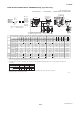
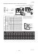
AXF Standard, AXF025-AXF050, JIS/ANSI/DIN Flange Type, PFA /Polyurethane Rubber /Natural Soft
Rubber /EPDM Rubber Lining
F30.EPS
Option
Code
None
GA, GC, GD
(Special Gaskets)
L t L t L t
Grounding Ring Code S, L, H, V P, T N
+0 +0
+26(1.02)
+13(0.51)
-2(0.08)
-1(0.04)
+8(0.31) +4(0.16)
+30(1.18)
+15(0.59) – –
*1: When indicator code N is selected, subtract 12 mm (0.47 inch) from the value in the figure.
In case of explosion proof type with indicator, add 5 mm (0.2 inch) to it.
*2: Depending on the selection of grounding ring code and optional code, add the following value to “L” (face-to-face length) and “t” (thickness
of flange).
*3: When submersible type or option code DHC is selected, waterproof glands and a 30m long cable are attached.
Add 9.5kg(20.9lb) to the weight in the table.
Unit : mm (approx. inch)
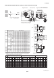
Remote FlowtubeIntegral FlowmeterRemote FlowtubeIntegral Flowmeter
AXF025
AXF032
AXF040
AXF050
G
W
C
D
E
F
G
N
P
1
2
N
A
U
D
G
1
2
B
B
B
C
C
C
A
J
D
A
J
D
4
4
*4: D, E, F, G; Integral Flowmeter,
N, P; Remote Flowtube
*4
H1
Hr
Hi
t *
2
L*
2
48
θ
°
N-øh
øD
øC
(ød)
197(7.76)*
1
(1.89)
ø86(3.38)
154(6.06)
49(1.93)
Ground Terminal
(M4)
111(4.37)
28(1.1)
66*
1
(2.6)
51.5
(2.03)
51.5
(2.03)
ø128(5.04)
70(2.76)
73
(2.87)
Ground Terminal
(M4)
(H2)
BJ1(JIS10K)
BJ1/CJ1
(JIS10K)
BJ2/CJ2
(JIS20K)
BJ2(JIS20K)
200
(7.87)
125
(4.92)
18
(0.71)
28
(1.10)
90
(3.54)
45
19
(0.75)
4
120
(4.74)
58
(2.28)
244
(9.62)
4.4
(9.8)
282
(11.09)
6.1
(13.5)
200
(7.87)
135
(5.31)
20
(0.79)
34
(1.34)
100
(3.94)
45
19
(0.75)
4
129
(5.08)
61
(2.40)
253
(9.96)
5.3
(11.7)
291
(11.46)
7.0
(15.5)
200
(7.87)
140
(5.51)
20
(0.79)
41
(1.61)
105
(4.13)
45
19
(0.75)
4
138
(5.43)
68
(2.67)
262
(10.31)
5.7
(12.6)
299
(11.79)
7.4
(16.4)
200
(7.87)
155
(6.10)
20
(0.79)
53
(2.09)
120
(4.72)
45
19
(0.75)
4
157
(6.16)
79
(3.11)
281
(11.04)
6.8
(14.9)
318
(12.52)
8.5
(18.6)
200
(7.87)
125
(4.92)
20
(0.79)
28
(1.10)
90
(3.54)
45
19
(0.75)
4
120
(4.74)
58
(2.28)
244
(9.62)
4.8
(10.5)
282
(11.09)
6.5
(14.3)
200
(7.87)
135
(5.31)
22
(0.87)
34
(1.34)
100
(3.94)
45
19
(0.75)
4
129
(5.08)
61
(2.40)
253
(9.96)
5.7
(12.6)
291
(11.46)
7.4
(16.4)
200
(7.87)
140
(5.51)
22
(0.87)
41
(1.61)
105
(4.13)
45
19
(0.75)
4
138
(5.43)
68
(2.67)
262
(10.31)
6.2
(13.6)
299
(11.79)
7.9
(17.4)
200
(7.87)
155
(6.10)
22
(0.87)
53
(2.09)
120
(4.72)
22.5
19
(0.75)
8
157
(6.16)
79
(3.11)
281
(11.04)
7.0
(15.4)
318
(12.52)
8.7
(19.1)
*
3
Max. Height
Hr
Hi
Weight kg (lb)
Max. Height
Weight kg (lb)
Height
Height
H2
H1
Size code
Size
Lining code
Face-to-face length
0
-3
L
*
2
*
2
Outside dia.
Inner diameter of
Grounding ring
Number of holes
N
Pitch circle dia.
Hole dia.
øh
øC
Bolt hole interval
θ˚
Thickness
t
Process Connection
ød
øD
Model
Remote
Flow
tube
Integral
Flowmeter
Remote
Flow
tube
Integral
Flowmeter
050
50
(2)
A,U
D,G
025
25
(1)
A,U
032
32
(1.25)
A,U
040
40
(1.5)
A,U
050
50
(2)
A,U
D,G
025
25
(1)
A,U
032
32
(1.25)
A,U
040
40
(1.5)
A,U
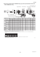
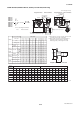
BA1(ANSI Class 150)
BA1/CA1
(ANSI Class 150)
BA2/CA2
(ANSI Class 300)
BA2(ANSI Class 300)
025
25
(1)
A,U
032
32
(1.25)
A,U
200
(7.87)
108.0
(4.25)
18.2
(0.72)
28
(1.10)
79.2
(3.12)
45
15.7
(0.62)
4
112
(4.40)
58
(2.28)
236
(9.28)
3.9
(8.5)
273
(10.76)
5.6
(12.2)
200
(7.87)
117.3
(4.62)
19.7
(0.78)
34
(1.34)
88.9
(3.50)
45
15.7
(0.62)
4
120
(4.72)
61
(2.40)
244
(9.61)
4.5
(9.9)
282
(11.10)
6.2
(13.6)
200
(7.87)
127.0
(5.00)
21.5
(0.85)
41
(1.61)
98.6
(3.88)
45
15.7
(0.62)
4
131
(5.17)
68
(2.67)
255
(10.05)
5.4
(11.9)
293
(11.53)
7.1
(15.7)
200
(7.87)
152.4
(6.00)
23.1
(0.91)
53
(2.09)
120.7
(4.75)
45
19.1
(0.75)
4
155
(6.11)
79
(3.11)
279
(10.99)
7.4
(16.4)
317
(12.47)
9.1
(20.1)
200
(7.87)
124.0
(4.88)
21.5
(0.85)
28
(1.10)
88.9
(3.50)
45
19.1
(0.75)
4
120
(4.72)
58
(2.28)
244
(9.60)
5.0
(11.0)
281
(11.07)
6.7
(14.7)
200
(7.87)
133.4
(5.25)
23.1
(0.91)
34
(1.34)
98.6
(3.88)
45
19.1
(0.75)
4
128
(5.04)
61
(2.40)
252
(9.92)
5.8
(12.9)
290
(11.42)
7.5
(16.6)
200
(7.87)
155.4
(6.12)
24.6
(0.97)
41
(1.61)
114.3
(4.50)
45
22.4
(0.88)
4
146
(5.73)
68
(2.67)
270
(10.61)
7.8
(17.1)
307
(12.09)
9.5
(20.8)
040
40
(1.5)
A,U
050
50
(2)
200
(7.87)
165.1
(6.50)
26.4
(1.04)
53
(2.09)
127.0
(5.00)
22.5
19.1
(0.75)
8
162
(6.36)
79
(3.11)
286
(11.24)
9.0
(19.8)
323
(12.72)
10.7
(23.6)
050
50
(2)
025
25
(1)
A,U
032
32
(1.25)
A,U
040
40
(1.5)
A,U
A,U
D,G
A,U
D,G
A,U
D,G
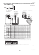
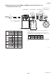
BD4(DIN PN40)
BD4/CD4
(DIN PN40)
025
25
(1)
A,U
032
32
(1.25)
A,U
200
(7.87)
115
(4.53)
22
(0.87)
28
(1.10)
85
(3.35)
45
14
(0.55)
4
115
(4.54)
58
(2.28)
239
(9.42)
4.7
(10.4)
277
(10.90)
6.4
(14.1)
200
(7.87)
140
(5.51)
22
(0.87)
34
(1.34)
100
(3.94)
45
18
(0.71)
4
131
(5.16)
61
(2.40)
255
(10.04)
6.1
(13.4)
293
(11.54)
7.8
(17.2)
200
(7.87)
150
(5.91)
22
(0.87)
41
(1.61)
110
(4.33)
45
18
(0.71)
4
143
(5.63)
68
(2.67)
267
(10.51)
6.9
(15.2)
304
(11.98)
8.6
(19.0)
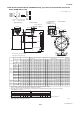
200
(7.87)
165
(6.50)
24
(0.94)
53
(2.09)
125
(4.92)
45
18
(0.71)
4
162
(6.36)
79
(3.11)
286
(11.24)
8.7
(19.2)
323
(12.72)
10.4
(22.9)
040
40
(1.5)
A,U
050
50
(2)
* No infra-red switches are furnished
for Fieldbus communication type.