
User Manual

IM 01E20D01-01E
6-36
6. OUTLINE
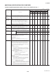
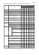
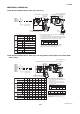
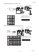
AXF Standard, AXF150-AXF300, Wafer Type, PFA /Polyurethane Rubber /Natural Soft Rubber /EPDM
Rubber Lining
Unit : mm (approx. inch)
Remote FlowtubeIntegral FlowmeterRemote FlowtubeIntegral Flowmeter
Ground Terminal
(M4)
ø128(5.04)
197(7.76)*
1
28(1.1)
66*
1
(2.6)
51.5
(2.03)
51.5
(2.03)
øD
(ød)
W*
3
111(4.37)
Hi
H1
Hr
48
ø86(3.38)
154(6.06)
L*
2
70(2.76)
73(2.87) 49(1.93)
Ground Terminal
(M4)
(1.89)
F24.EPS
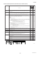
*1: When indicator code N is selected, subtract 12 mm (0.47 inch)
from the value in the figure.
In case of explosion proof type with indicator, add 5 mm (0.2 inch) to it.
*2: Depending on the selection of grounding ring code and optional
code, add the following value to L (face-to-face length).
*3: When electrode structure 2 is selected, add the following value to
W(width).
*4: When submersible type or option code DHC is selected,
waterproof glands and a 30m long cable are attached.
Add 9.5kg(20.9lb) to the weight in the table.
Option
Code
None
GA, GC, GD
(Special Gaskets)
Grounding Ring Code S, L, H, V P, T N
+0 +32(1.26)
-2(0.08)
+10(0.39) +38(1.5) –
Nominal Size: 150 to 200mm
Grounding Ring Code S, L, H, V P, T N
Option Code is “None” +0 –
-2(0.08)
Nominal Size: 250 to 300mm
Nominal size
W
150
+49(1.93)
200
+50(1.97)
250
+49(1.93)
300
+53(2.09)
AXF150
AXF200
AXF250
AXF300
G
W
C
D
E
F
G
N
P
1
2
N
A
U
D
G
1
2
A
1
*5: D, E, F, G; Integral Flowmeter,
N, P; Remote Flowtube
*5
* In case of size
250mm or 300mm,
position of grounding
ring is different
from the figure to
45-degree.
* No infra-red switches are furnished
for Fieldbus communication type.
150
150(6)
A,U
D,G
200(7.87)
202(7.95)
146.1(5.75)
202(7.95)
243(9.57)
367(14.45)
14.5(32.0)
405(15.93)
16.2(35.7)
200
200(8)
A,U
D,G
250(9.84)
252(9.92)
193.6(7.62)
252(9.92)
293(11.54)
417(16.42)
22.1(48.7)
455(17.89)
23.8(52.4)
250
250(10)
A,U
D,G
300(11.81)
310(12.20)
243.7(9.59)
310(12.20)
354(13.94)
478(18.82)
39.0(86.0)
516(20.31)
40.7(89.7)
300
300(12)
A,U
D,G
350(13.78)
358(14.09)
294.7(11.60)
358(14.09)
402(15.83)
526(20.71)
48.3(106.5)
564(22.20)
50.0(110.2)
W
*
4
Max. Height
Hr
Hi
Weight kg (lb)
Max. Height
Weight kg (lb)
Height
H1
Size code
Size
Lining code
Face-to-face
length
*
3
Outside dia.
ø
D
Inner diameter of
Grounding ring
ø
d
Width
Model
Remote
Flow
tube
Integral
Flowmeter
Remote
Flow
tube
Integral
Flowmeter
L
*
2
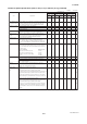
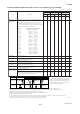
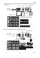
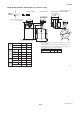
AXF Standard, AXF002-AXF010, Weld · Union Joint, Ceramics Lining
Unit : mm (approx. inch)
Remote FlowtubeIntegral FlowmeterRemote FlowtubeIntegral Flowmeter
ø86(3.38)
48(1.89)
70(2.76)H1
Hr
49(1.93)
154(6.06)
73(2.87)
L
Hi
Ground Terminal
(M4)
111(4.37)
28(1.1)
197(7.76)*
1
ø128(5.04)
Ground Terminal
(M4)
51.5
(2.03)
51.5
(2.03)
58
72
(2.83)
(2.28)
4- ø6.2(0.24)
66*
1
(2.6)
*2: D, E, F, G; Integral Flowmeter,
N, P; Remote Flowtube
*2
3(0.12)
63.5(2.50)
øB
øB
øC
øC
øD
øA
øA
D
11.5
30(1.18)
4(0.16)
4(0.16)
10
35(1.38)
22(0.87)
22(0.87)
22(0.87)
22(0.87)
25(0.98)
25(0.98)
2.5
(0.1)
5
(0.2)
10
(0.4)
8(0.31)
8(0.31)
8(0.31)
8(0.31)
10(0.39)
10(0.39)
18.5(0.73)
18.5(0.73)
18.5(0.73)
18.5(0.73)
22.5(0.89)
22.5(0.89)
R1/4
NPT1/4
R1/4
NPT1/4
R3/8
NPT3/8
Size A B C
D
2.5(0.1)
5(0.2)
10(0.4)
Size
22(0.87)
22(0.87)
25(0.98)
A
8(0.31)
8(0.31)
10(0.39)
B
14.3(0.56)
14.3(0.56)
17.8(0.70)
C
18.5(0.73)
18.5(0.73)
22.5(0.89)
D
Weld joint
Union joint
(0.39)
(0.45)
F25.EPS
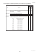
*1: When indicator code N is selected, subtract 12 mm (0.47 inch)
from the value in the figure.
In case of explosion proof type with indicator, add 5 mm (0.2 inch) to it.
Process connection GUW (Welding type)
GUN/GUR (Union joint type)
002
2.5
(0.1)
C
005
5
(0.2)
C
010
10
(0.4)
C
002
2.5
(0.1)
C
005
5
(0.2)
C
010
10
(0.4)
C
140(5.51)
144(5.67)
268(10.55)
2.3(5.1)
306(12.03)
4(8.8)
130(5.12)
144(5.67)
268(10.55)
2.3(5.1)
306(12.03)
4(8.8)
Max. Height
Hr
Hi
Weight kg (lb)
Max. Height
Weight kg (lb)
Height
H1
Size code
Size
Lining code
Face-to-face
length
L
Model
Remote
flowtube
Integral
flowmeter
Remote
flowtube
Integral
flowmeter
AXF002
AXF005
AXF010
G
C
D
E
F
G
N
P
1
2
N
W
N
R
CE1N GU
1
* No infra-red switches are furnished
for Fieldbus communication type.