User’s Manual AXW Magnetic Flowmeter Remote Flowtube IM 01E25D11-01EN IM 01E25D11-01EN 2nd Edition
i AXW Magnetic Flowmeter Remote Flowtube IM 01E25D11-01EN 2nd Edition Contents 1. 2. 3. INTRODUCTION......................................................................................... 1-1 1.1 Using the Magnetic Flowmeter Safely............................................................. 1-2 1.2 Warranty.............................................................................................................. 1-3 1.3 Combination Remote Converters...........................................
ii n OPTIONAL SPECIFICATIONS .......................................................................... 6-5 n OPTIONAL SPECIFICATIONS (continued)...................................................... 6-6 n DIMENSIONAL DRAWINGS.............................................................................. 6-7 n SIZING DATA..................................................................................................... 6-19 Revision Information.......................................................
1. 1-1 <1. INTRODUCTION> INTRODUCTION This instrument has been adjusted at the factory before shipment. To ensure correct use of the instrument, please read this manual thoroughly and fully understand how to operate the instrument before operating it. NOTE The ADMAG AXW remote flowtube is used in combination with the AXFA11 remote converter. This manual describes the hardware configuration of the ADMAG AXW remote flowtube.
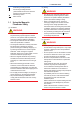
Protective grounding terminal Functional grounding terminal (This terminal should not be used as a protective grounding terminal.) Alternating current Direct current 1.1 Using the Magnetic Flowmeter Safely (1) Installation WARNING • Installation of the magnetic flowmeter must be performed by expert engineer or skilled personnel. No operator shall be permitted to perform procedures relating to installation. • The magnetic flowmeter must be installed within the specification conditions.
(4) Maintenance WARNING • Maintenance of the magnetic flowmeter should be performed by the trained personnel having knowledge of safety standard. No operator shall be permitted to perform any operations relating to maintenance. • When opening the cover, wait for more than 10 minutes after turning off the power. • Do not open the cover in wet weather or humid environment. When the cover is open, stated enclosure protection is not applicable.
Blank Page
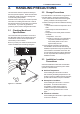
<2. HANDLING PRECAUTIONS> 2. HANDLING PRECAUTIONS This instrument has been inspected carefully at the factory before shipment. When the instrument is delivered, visually check that no damage has occurred during transportation. Read this section carefully as it contains important information on handling this instrument. Refer to the relevant sections for information not contained in this section. If you have any problems or questions, please contact Yokogawa sales office. 2.
Blank Page
3. INSTALLATION WARNING Installation of the magnetic flowmeter must be performed by expert engineer or skilled personnel. No operator shall be permitted to perform procedures relating to installation. 3.1 3-1 <3. INSTALLATION> Piping Design Precautions IMPORTANT Design piping correctly, referring to the following to prevent damage to flowtubes and to assure accurate measuring. (1) Location IMPORTANT Install the flowmeter in a location where it is not exposed to direct sunlight.
3-2 <3. INSTALLATION> (5) Precautions for Use of Liquid Sealing Compounds IMPORTANT Care must be taken in using liquid sealing compounds on the piping, as it may have a negative influence on the flow indications by flowing out and covering the surfaces of an electrode or grounding ring. In particular, care must be taken if a liquid sealing compound is used in the case of vertical piping.
<3. INSTALLATION> 3-3 • Mounting orientation IMPORTANT 90 degrees or less If electrodes are perpendicular to the ground, air bubbles near the top or precipitates at the bottom may cause measurement errors. Ensure that the terminal box of a remote flowtube is mounted above the piping to prevent water from entering them. Eye bolt Correct 90 degrees or less Eye plate F0307.ai Incorrect Incorrect Figure 3.2.
3-4 <3. INSTALLATION> • Confirmation of sealing conditions for the flowmeter Confirm that the terminal box screw and wiring ports are well sealed. Equip the conduit piping with drain plugs or waterproof glands to prevent moisture or water from penetrating into the flowmeter through the conduit. • Regular inspections Inspect the sealing conditions as mentioned above, and the inside of the terminal box at least once a year. Also, due to rain, etc.
3-5 <3. INSTALLATION> (2) Carrying Flowtube 90 degrees or less Eye bolt 1. Standard (no grounding rings) 90 degrees or less Customer pipe Customer pipe A Eye plate A Gaskets A supplied by customer F0310.ai Figure 3.3.2 Installation without Grounding Rings F0309.ai Figure 3.3.1 Carrying Flowtube When using the GF type-1 gaskets, the gasket groove is required as mentioned above. 2.
Mounting Procedure (with optional Grounding Rings GR1 for sizes up to 1000 mm (40 in.)): 1. Handles of the grounding ring have some holes which correspond to outer diameter of each flange type. There are printings near each hole. The printings show types of flange. See the table below. Printing 3-6 <3. INSTALLATION> Process Connection Code ASME -CA1 AWWA -CB1 PN10 PN16 10K -CE1 -CE2 -CJ1 AS -CS1, -CS2, -CT1 F12 -CG1 5. Install the flowtube into the customer’s pipe with the gaskets A.
<3. INSTALLATION> 3-7 5. Install the flowtube into the customer’s pipe with the gaskets A. Screw & Nut : Connect the wire from the grounding ring or the customer’s pipe. Hang the grounding ring up with this point. Unfasten the bolts and remove the grounding rings. Cut out some holes on the gasket B when necessary. Wire Flowtube Grounding Ring F0314.ai Note : Gasket A and B should be placed concentrically with the flowtube. Figure 3.3.
Table 3.3.1 3-8 <3. INSTALLATION> Tightening Torque Values for Metal Piping (N-m) Unit: N-m Lining type PTFE / Natural hard rubber / Natural soft rubber Gasket type Soft rubber gasket, or the equivalent in hardness (supplied by customer) ASME Process AWWA C207 AS2129 Table D, E connection B16.5 (500, 600) EN1092-1 PN10 EN 1092-1 PN16 Class D AS4087 PN16 Size B16.
Table 3.3.2 3-9 <3. INSTALLATION> Tightening Torque Values for Metal Piping (lbf-in) Unit: lbf-in Lining type PTFE / Natural hard rubber / Natural soft rubber Gasket type Soft rubber gasket, or the equivalent in hardness (supplied by customer) ASME Process AWWA C207 AS2129 Table D, E connection B16.5 (500, 600) EN1092-1 PN10 EN 1092-1 PN16 Class D AS4087 PN16 Size B16.
Blank Page
4. 4.1 <4. WIRING> 4-1 WIRING Wiring the Remote Flowtube This section describes the wiring of the remote flowtube only. For information relating to the wiring of the converter, refer to the user’s manual of the AXFA11 Magnetic Flowmeter Remote Converter (IM 01E20C01-01E). WARNING The wiring of the magnetic flowmeter must be performed by expert engineer or skilled personnel. No operator shall be permitted to perform procedures relating to wiring.
<4. WIRING> 4.1.2 Cables CAUTION (1) Dedicated Signal Cable (AXFC) • As crimp terminals A, B, SA, SB and C have their own electrical potentials, securely insulate them so as not to come in contact with one another. • To prevent a shield from coming in contact with another shield or the case, cover each shield with a vinyl tube or wrap it in vinyl tape. Conductors (A and B) Shields (SA and SB) Tape Outer jacket 10.5 (0.413") Shield (C) Insulation Insulation NOTE F0401.ai Figure 4.1.
Unit : mm (approx. inch) 85 (3.35) On the converter side EX2 EX2 EX1 Crimp terminal EX1 4-3 <4. WIRING> 85 (3.35) On the flowtube side 4.1.3 Wiring Ports This instrument is of watertight construction as stipulated in JIS C0920. It is shipped with a wiring bracket (waterproof gland or waterproof gland with union), only in cases where an optional specification is selected for the wiring port.
4-4 <4. WIRING> 4.1.4 Wiring Connections WARNING Washer Before wiring, be sure that the power supply for AXFA11 converter has been turned off to prevent an electrical shock. Gasket Waterproof gland Cable F0404.ai Figure 4.1.4 Waterproof Gland (Optional code EG) (1) Removing Cover Loosen the cover locking screw clockwise using a hexagonal wrench (nominal size 3 mm) to unlock the cover. (Upon shipment from the manufacturing plant, the cover is unlocked.
4-5 <4. WIRING> (3) Wiring the Remote Flowtube with AXFA11 Converters Connect wiring as shown in the figure below. I+ I– CURRENT OUT 4-20mA out SO1+ SO2+ COM STATUS OUT AL+ AL– ALARM OUT C SA A SIGNAL N/– L/+ POWER SUPPLY SB AXFA11 converter FUSE 2.
Blank Page
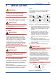
5. <5. MAINTENANCE> 5-1 MAINTENANCE WARNING • Maintenance work must be carried out by the trained personnel having knowledge of safety standard and not by operators. • When opening the cover, wait for more than 10 minutes after turning off the power. Furthermore, opening of the cover must also be carried out by the trained personnel having knowledge of safety standard. CAUTION • When opening the cover, use a hexagonal wrench (nominal size 3 mm).
5.2 Regular Inspection Items (1) Inspection of moisture-proofing inside the terminal box: Once/year (2) Retightening of piping joint screws: About twice/year (3) Inspection of electrodes and lining (in case of adhesive and/or abrasive fluids, etc.) Determine the period of regular inspection as necessary. 5.
5.4 <5. MAINTENANCE> 5-3 Troubleshooting Although magnetic flowmeters rarely require maintenance, failures may occur when the instrument is not operated correctly. This section describes troubleshooting procedures where the cause of the breakdown is identified through receiver indication. 5.4.1 No Indication START Is an error being displayed? Check the converter display. Is an error being displayed? YES Refer to the “Alarm Functions” in the AXFA11.
<5. MAINTENANCE> 5-4 5.4.2 Unstable Zero START Investigate whether or not the flowtube is filled with fluid and that it is free of bubbles. *1 Is the flowtube completely full of fluid? NO *1: When checking for bubbles, it is convenient if there is a gas vent hole on the flowtube’s downstream side. Particular care must be taken in the case of horizontal mounting. In order to ensure complete filling of the tube, either adjust the mounting position or switch to vertical mounting.
<5. MAINTENANCE> 5-5 5.4.3 Disagreement Between Indication and Actual Flow START NO Are parameters set correctly? Set the parameters correctly. YES Examine the condition of the fluid in the flowtube, of bubbles, and of grounding. Was zero adjustment carried out correctly? Execute zero adjustment when the flowtube is filled completely with fluid and when the fluid is not moving.
Blank Page
6. 6-1 <6. OUTLINE> OUTLINE n STANDARD SPECIFICATIONS Protection: General-purpose type: IP66, IP67 Submersible type: IP68 (conforms to continuous immersion under the following test condition) Test Condition: 50 m below the surface of the water, equivalent to 0.5 MPa hydraulic pressure, for one month.Cable should be protected at customer site.
Note: The accuracy of a product before shipment is defined as totalized value at the result of calibration test in our water actual flow test facility. Calibrated conditions in our water actual test facility are as follows: Fluid temperature: 20 ± 10°C Ambient temperature: 20 ± 5°C Length of straight runs: 10 D or more on the upstream side 5 D or more on the downstream side Reference conditions: Similar to BS EN29104, ISO 9104 Accuracy (Current Output): Accuracy (Pulse Output) plus ±0.
6-3 <6. OUTLINE> MODEL AND SUFFIX CODE l For Process Connections other than JIS F12 (JIS 75M) Model Suffix Code Description AXW500 Size 500 mm (20 in.) Remote Flowtube AXW600 Size 600 mm (24 in.) Remote Flowtube AXW700 Size 700 mm (28 in.) Remote Flowtube AXW800 Size 800 mm (32 in.) Remote Flowtube AXW900 Size 900 mm (36 in.) Remote Flowtube AXW10L Size 1000 mm (40 in.) Remote Flowtube AXW12L Size 1200 mm (48 in.) Remote Flowtube AXW14L Size 1400 mm (56 in.
6-4 <6. OUTLINE> l For Process Connection JIS F12 (JIS 75M) Model AXW500 AXW600 AXW700 AXW800 AXW900 AXW10L AXW11L AXW12L AXW13L AXW15L AXW16L AXW18L Use Suffix Code Description Size 500 mm (20 in.) Remote Flowtube Size 600 mm (24 in.) Remote Flowtube Size 700 mm (28 in.) Remote Flowtube Size 800 mm (32 in.) Remote Flowtube Size 900 mm (36 in.) Remote Flowtube Size 1000 mm (40 in.) Remote Flowtube Size 1100 mm (44 in.) Remote Flowtube Size 1200 mm (48 in.) Remote Flowtube Size 1350 mm (54 in.
6-5 <6. OUTLINE> OPTIONAL SPECIFICATIONS ○ : Available – : Not available Applicable Model Item Specifications General Submersible AXW***G AXW***W Code Grounding Rings (*1) JIS SUS304 (AISI 304 SS Equivalent), a set of two rings ○ ○ GR1 Grounding Rings (*2) SUSF304 (AISI 304 SS Equivalent), a set of two rings with gaskets “B”. ○ ○ GR2 For District Heating and Cooling or Condensation-proof Urethane resin potting is applied in the terminal box of a remote flowtube.
6-6 <6. OUTLINE> OPTIONAL SPECIFICATIONS (continued) ○ : Available – : Not available Applicable Model Item Hydrostatic Test Specifications Submersible AXW***G AXW***W ○ ○ T01 Level 2: The Declaration and the Calibration Equipment List are issued. ○ ○ L2 Level 3: The Declaration and the Primary Standard List are issued. ○ ○ L3 Level 4: The Declaration and the Yokogawa Measuring Instruments Control System are issued.
6-7 <6. OUTLINE> DIMENSIONAL DRAWINGS l AXW500 to AXW10L, Sizes 500 mm (20 in.) to 1000 mm (40 in.) Ground Terminal (M4) 111 (4.37) ø 86 (3.38) 48 (1.89) Eye Bolt θ° (ød) øC Hr H1 øD ( H2) N- ø h L (*) *: The thickness of optional grounding rings (4mm per one) and customer supplied gaskets are not included in “L” here. F0603.ai (1) ASME Flange Type Unit: mm (approx. in.) Process Connection Code Flange Type CA1 ASME B16.5 Class150 Size Code Size ASME B16.
6-8 <6. OUTLINE> (2) AWWA Flange Type Unit: mm (approx. in.) Process Connection Code CB1 Flange Type AWWA C207 Class D Size Code Size 700 800 700 (28) 800 (32) Lining Code 900 10L 900 (36) 1000 (40) H, F, U, D Lay Length L 840 (33.07) 960 (37.80) 1080 (42.52) 1200 (47.24) Flange Outer Diameter øD 927 (36.50) 1060 (41.75) 1168 (46.00) 1289 (50.75) Bolt Circle Diameter øC Inner Diameter ød 863.6 (34.00) 977.9 (38.50) 1086 (42.75) 1200 (47.25) Lining H, F, D 675 (26.
6-9 <6. OUTLINE> (4) EN PN16 Flange Type (fluid pressure up to 1 MPa) Unit: mm (approx. in.) Process Connection Code CE2 Flange Type EN1092-1 PN16 Size Code 500 600 700 800 900 10L 500 (20) 600 (24) 700 (28) 800 (32) 900 (36) 1000 (40) Lay Length L 600 (23.62) 720 (28.35) 840 (33.07) 960 (37.80) 1080 (42.52) 1200 (47.24) Flange Outer Diameter øD 715 (28.15) 840 (33.07) 910 (35.83) 1025 (40.35) 1125 (44.29) 1255 (49.41) Bolt Circle Diameter øC 650 (25.59) 770 (30.
<6. OUTLINE> (6) AS2129 Table D Flange Type 6-10 Unit: mm (approx. in.) Process Connection Code CS1 Flange Type AS2129 Table D Size Code Size 500 600 700 500 (20) 600 (24) 700 (28) Lining Code 800 900 10L 800 (32) 900 (36) 1000 (40) H, F, U, D Lay Length L 600 (23.62) 720 (28.35) 840 (33.07) 960 (37.80) 1080 (42.52) 1200 (47.24) Flange Outer Diameter øD 705 (27.76) 825 (32.48) 910 (35.83) 1060 (41.73) 1175 (46.26) 1255 (49.41) Bolt Circle Diameter øC 641 (25.
<6. OUTLINE> (8) AS4087 PN16 Flange Type 6-11 Unit: mm (approx. in.) Process Connection Code CT1 Flange Type AS4087 PN16 Size Code 500 600 700 800 900 10L 500 (20) 600 (24) 700 (28) 800 (32) 900 (36) 1000 (40) Lay Length L 600 (23.62) 720 (28.35) 840 (33.07) 960 (37.80) 1080 (42.52) 1200 (47.24) Flange Outer Diameter øD 705 (27.76) 825 (32.48) 910 (35.83) 1060 (41.73) 1175 (46.26) 1255 (49.41) Size Lining Code H, F, U, D Bolt Circle Diameter øC 641 (25.24) 756 (29.
<6. OUTLINE> 6-12 l Optional Grounding Rings (GR1) for sizes 500 mm (20 in.) to 1000 mm (40 in.) øD L2 L1 ø25 (0.98) (ød) L2 L1 F0604.ai Unit: mm (approx. in.) Process Connection Code Size Code Size CA1, CB1, CE1, CE2, CJ1, CS1, CS2, CT1, CG1 500 600 700 500 (20) 600 (24) 700 (28) Lining Code 800 900 10L 800 (32) 900 (36) 1000 (40) H, F, U, D Ring Outer Diameter øD 590 (23.23) 690 (27.17) 799 (31.46) 906 (35.67) 1006 (39.61) 1116 (43.94) Ring Inner Diameter ød 485 (19.
6-13 <6. OUTLINE> l AXW11L to AXW18L, Sizes 1100 mm (44 in.) to 1800 mm (72 in.) Ground Terminal (M4) 111 (4.37) ø86 (3.38) 48 (1.89) θ° 4-M8 (for Grounding Ring) (Except for JIS F12 flange models) (H2) Eye Plate øC 2( øC1 (ø M8 Hr h) T L (*) N-øh ) øD (ød) *: The thickness of optional grounding rings (5 mm for GR1 and 25 mm for GR2 per one) and customer supplied gaskets are not included in “L” here. F0605.ai (1) AWWA Flange Type Unit: mm (approx. in.
<6. OUTLINE> 6-14 (2) EN PN6 Flange Type Unit: mm (approx. in.) Process Connection Code CEJ Flange Type EN1092-1 PN6 Size Code Size 12L 14L 1200 (48) 1400 (56) Lining Code 16L 18L 1600 (64) 1800 (72) H Lay Length L 1440 (56.69) 1680 (66.14) 1920 (75.59) 2160 (85.04) Flange Outer Diameter øD 1405 (55.31) 1630 (64.17) 1830 (72.05) 2045 (80.51) Flange Bolt Circle Diameter øC1 1340 (52.76) 1560 (61.42) 1760 (69.29) 1970 (77.56) Ring Bolt Circle Diameter øC2 1356 (53.
<6. OUTLINE> 6-15 (4) EN PN10 Flange Type Unit: mm (approx. in.) Process Connection Code CE1 Flange Type EN1092-1 PN10 Size Code Size 12L 14L 1200 (48) 1400 (56) Lining Code 16L 18L 1600 (64) 1800 (72) H Lay Length L 1440 (56.69) 1680 (66.14) 1920 (75.59) 2160 (85.04) Flange Outer Diameter øD 1455 (57.28) 1675 (65.94) 1915 (75.39) 2115 (83.27) Flange Bolt Circle Diameter øC1 1380 (54.33) 1590 (62.60) 1820 (71.65) 2020 (79.53) Ring Bolt Circle Diameter øC2 1391 (54.
<6. OUTLINE> 6-16 (6) JIS F12 (JIS 75M) Flange Type Unit: mm (approx. in.) Process Connection Code CG1 Flange Type JIS G3443-2 F12 Size Code Size 11L 12L 13L 1100 (44) 1200 (48) 1350 (54) Lining Code 15L 16L 18L 1500 (60) 1600 (64) 1800 (72) U Lay Length L 1320 (51.97) 1440 (56.69) 1620 (63.78) 1800 (70.87) 1920 (75.59) 2160 (85.04) Flange Outer Diameter øD 1366 (53.78) 1470 (57.87) 1642 (64.65) 1800 (70.87) 1915 (75.39) 2115 (83.27) Bolt Circle Diameter øC 1283 (50.
6-17 <6. OUTLINE> l Optional Grounding Rings (GR1) for sizes 1200 mm (48 in.) to 1800 mm (72 in.) L2 ø35 (1.38) øC (ød) ø11 (0.43) L1 øD L1 L1 F0606.ai Unit: mm (approx. in.) Process Connection Code Flange Type CB1, CS1, CS2,CT1 CEJ CEK, CE1 AWWA C207-D AS2129-D,E AS4087 PN16 EN PN6 EN PN10 Size Code 12L 12L 14L 16L 18L 12L 14L 16L 18L Size 1200 (48) 1200 (48) 1400 (56) 1600 (64) 1800 (72) 1200 (48) 1400 (56) 1600 (64) 1800 (72) Ring Outer Diameter øD 1370 (53.
6-18 <6. OUTLINE> l Optional Grounding Rings (GR2) for sizes 1100 mm (44 in.) to 1800 mm (72 in.) Unit: mm (approx. in.) Process Connection Code CG1 Flange Type JIS F12 (JIS 75M) Size Code 11L 12L 13L 15L 16L 18L Size 1100 (44) 1200 (48) 1350 (54) 1500 (60) 1600 (64) 1800 (72) 92.4 (204) 114.2 (252) Lining Code U Thickness Approx. Weight, Unit: kg (lb) 25 (0.98) 59.3 (131) 65.7 (145) 75.8 (167) 88.
6-19 <6. OUTLINE> Note: Unless otherwise specified, refer to the following table for tolerance in the dimensions. General tolerance in the dimensional outline drawing. Unit: mm (approx. in.) Category of basic dimension Above 3 (0.12) 6 (0.24) 10 (0.39) 18 (0.71) 30 (1.18) 50 (1.97) 80 (3.15) 120 (4.72) 180 (7.09) 250 (9.84) 315 (12.40) 400 (15.75) Equal or below 3 (0.12) 6 (0.24) 10 (0.39) 18 (0.71) 30 (1.18) 50 (1.97) 80 (3.15) 120 (4.72) 180 (7.09) 250 (9.84) 315 (12.40) 400 (15.75) 500 (19.
Blank Page
i Revision Information Title Manual No. Edition 1st 2nd : AXW Magnetic Flowmeter Remote Flowtube : IM 01E25D11-01EN Data Mar. 2012 Sep. 2013 Page – – Revised Item New publication Addition of sizes from 1100 mm (44 in.) to 1800 mm (72 in.). Addition of lining material and flange standard.