User’s Manual AXFA14G/C Magnetic Flowmeter Remote Converter [Hardware Edition/Software Edition] AXF Magnetic Flowmeter Integral Flowmeter [Software Edition] Manual Change No. 13-008-E Please use the attached sheets for the pages listed below in IM 01E20C02-01E (10th). Page and Item Contents of Correction Page 1-2, 1-3 1.1 Using the Magnetic Flowmeter Safety Added the warning notes in (1) installation, (3) Operation, and (4) Maintenance. Page 1-4, 1-5, 1-6 1.
1. INTRODUCTION • All procedures relating to installation must comply with the electrical code of the country where it is used. IMPORTANT An IMPORTANT sign denotes that attention is required to avoid damage to the instrument or system failure. (2) Wiring WARNING • The wiring of the magnetic flowmeter must be performed by expert engineer or skilled personnel. No operator shall be permitted to perform procedures relating to wiring.
1. INTRODUCTION 1.2 Warranty (4) Maintenance WARNING • The terms of this instrument that are guaranteed are described in the quotation. We will make any repairs that may become necessary during the guaranteed term free of charge. • Please contact our sales office if this instrument requires repair. • If the instrument is faulty, contact us with concrete details about the problem and the length of time it has been faulty, and state the model and serial number.
1. INTRODUCTION 1.3 Combination Remote Flowtubes IMPORTANT • The AXFA14 Magnetic Flowmeter Converter should be used in combination with the following remote flowtubes: AXFA14ⵧ⇔AXF002ⵧ-P to AXF400ⵧ-P Other flowtubes (size 500 to 2600 mm) cannot be combined with the AXFA14 converter. • If the converter combined with the AXF magnetic flowmeter remote flowtube is changed from the AXFA11 to AXFA14 or vice versa, the meter factor of the remote flowtube must be readjusted according to its flow calibration.
1. INTRODUCTION 1.4 ATEX Documentation SF This procedure is only applicable to the countries in European Union. Kaikkien ATEX Ex -tyyppisten tuotteiden käyttöhjeet ovat saatavilla englannin-, saksan- ja ranskankielisinä. Mikäli tarvitsette Ex -tyyppisten tuotteiden ohjeita omalla paikallisella kielellännne, ottakaa yhteyttä lähimpään Yokogawa-toimistoon tai -edustajaan. GB All instruction manuals for ATEX Ex related products are available in English, German and French.
1.
4. WIRING 4. WIRING • Ground the remote flowtube and the converter separately. • Cover each shield of the signal cable with vinyl tube or vinyl tape to avoid contact between two shields or between a shield and a case. • When waterproof glands or union equipped waterproof glands are used, avoid tightening the glands with an excessive torque. • In case of 24V power supply version, it comes with a plug. Use this plug to cover the unused wiring port when wiring the instrument with only one, four-core cable.
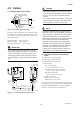
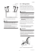
4. WIRING 4.2 Cables CAUTION • As crimp terminals A, B, SA, SB and C have their own electrical potentials, securely insulate them so as not to come in contact with one another. • To prevent a shield from coming in contact with another shield or the case, cover each shield with a vinyl tube or wrap it in vinyl tape. (1) Dedicated Signal Cable (AXFC) Conductors (A and B) Shields (SA and SB) Tape Outer jacket 10.5 (0.413") Shield (C) Insulation Insulation F0401.EPS NOTE Figure 4.2.
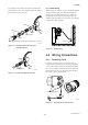
4. WIRING 4.3 Wiring Ports Unit : mm (approx. inch) 85 (3.35) 85 (3.35) On the converter side On the flowtube side This instrument is of watertight construction as stipulated in JIS C0920. It is shipped with a wiring bracket (waterproof gland or waterproof gland with union) or a plastic gland attached, only in cases where an optional specification is selected for the wiring port. In case of the explosion proof type, refer to chapter 12.
4. WIRING (3) Conduit Wiring When wiring the conduits, pass the conduit through the wiring connection port, and utilize the waterproof gland to prevent water from flowing in. Place the conduit pipe on an angle as shown in Figure 4.3.4. Install a drain valve at the low end of the vertical pipe, and open the valve regularly. For working on the electric wire tubes or the flexible tubes (PF1/2), remove the waterproof gland and attach them directly to the wiring port.
4. WIRING 4.4.2 Terminal Configuration 4.4.3 When the cover is removed, the connection terminals will be visible. The terminal configuration labels are attached in the locations shown in Figure 4.4.2. Precautions for Wiring of Power Supply Cables When connecting to the power supply, observe the points below. Failure to comply with these warnings may result in an electric shock or damage to the instrument. WARNING • Ensure that the power supply is OFF in order to prevent electric shocks.
4. WIRING 4.4.4 DC Power Connection 4.4.5 When using DC power as the power supply for the converter, give attention to the following points. Grounding CAUTION Be sure to connect the protective grounding of the AXFA14 with a cable of 2mm2 or larger cross section in oder to avoid electrical shock to the operators and maintenance engineers and to prevent the influence of external noise. Connect the grounding wire to the mark.
4. WIRING 4.4.6 Wiring the Remote Flowtube with the AXFA14 Converter AXFA14 Converter EX1 EX2 Excitation cable C AXFC dedicated signal cable WARNING SA A Before wiring, be sure that the power supply for AXFA14 converter has been turned off to prevent an electrical shock. B SB Converter SA A B SB C EX1 EX2 A EX2 B (1) Connection with the Remote Flowtube (General-Purpose Use, Submersible Type, Sanitary Type, Size 2.5 to 400 mm (0.1 to 16 in.)) Connect wiring as shown in the figure below.
4. WIRING 䊉 Pulse Output AXFA14 Protective diode DO+ Mechanical Counter PULSE OUT DO- IMPORTANT • As this is a transistor contact (insulated type), give attention to proper voltage and polarity when wiring. • Do not apply a voltage larger than 30V DC or a current larger than 0.2A in order to prevent damage to the instrument. • When input filter constant of the electronic counter is large in relation to the pulse width, the signal will decrease and the count will not be accurate.
4. WIRING This output cannot switch an AC load. To switch an AC load, an intermediate relay must be inserted as shown in Figure 4.4.11. *The alarm output operates from open (normal) to closed (alarm occurrence) in the default value (as setup upon plant shipment). Changes can be made via the parameter settings. AXFA14 Protective diode DO+ (or DIO+) Load DO- (or DIO-) This connection is not possible. AXFA14 DO+ (or DIO+) Relay Electromagnetic valve DO- (or DIO-) External power supply 30V DC, 0.2A.
11. OUTLINE Accuracy (Combined with AXF Remote Flowtube) Size 25 mm (1.0 in.) to 400 mm (16 in.) % of Rate 1.2 Pulse Output: PFA/Ceramics Lining: 1.0 0.8 High grade Standard Size mm Flow Velocity Accuracy Flow Velocity Accuracy (in.) V m/s (ft/s) (Calibration V m/s (ft/s) (Calibration code B) code C) 2.5 (0.1) to 15 (0.5) V 0.3 (1) 1.0 mm/s — 0.3 V 10 0.35% of (1) (33) Rate V 0.15 (0.5) 0.5 mm/s 25 (1.0) to 0.15 V 10 0.35% of 200 (8.0) (0.5) (33) Rate 250 (10) to 400 (16) Pulse 0.
11. OUTLINE Safety Requirement Standards: EN61010-1 EN61010-2-030 • Altitude at installation site: Max. 2000 m above sea level • Installation category based on IEC1010: Overvoltage category II (“II” applies to electrical equipment which is supplied from a fixed installation-like distribution board.) • Pollution degree based on IEC1010 Pollution degree 2 (“Pollution degree” describes the degree to which a solid, liquid, or gas which deteriorates dielectric strength or surface resistivity is adhering.
12. EXPLOSION PROTECTED TYPE INSTRUMENT For CSA C22.2 Series Explosion proof for Class I, Division 1, Groups A, B, C & D. Dust-ignition proof for Class II/III, Division 1, Groups E, F & G. “SEAL ALL CONDUITS WITHIN 50 cm OF THE ENCLOSURE” “WHEN INSTALLED IN DIV. 2, SEALS NOT REQUIRED” (3) Operation WARNING • “OPEN CIRCUIT BEFORE REMOVING COVERS.” • “SEAL ALL CONDUITS WITHIN 18 INCHES” in hazardous locations.