
User Manual

IM 01E20C02-01E
11. OUTLINE
Safety Requirement Standards:
EN61010-1
EN61010-2-030
• Altitude at installation site: Max. 2000 m above sea level
• Installation category based on IEC1010:
Overvoltage category II (“II” applies to electrical equip-
ment which is supplied from a fixed installation-like
distribution board.)
• Pollution degree based on IEC1010
Pollution degree 2 (“Pollution degree” describes the
degree to which a solid, liquid, or gas which deteriorates
dielectric strength or surface resistivity is adhering. “2”
applies to a normal indoor atmosphere.)
EMC Conformity Standards:
,
EN61326-1 Class A, Table 2 (For use in industrial locations)
EN61326-2-3
EN61000-3-2 ClassA
EN61000-3-3
CAUTION
This instrument is a Class A product, and it is
designed for use in the industrial environment. Please
use this instrument in the industrial environment only.
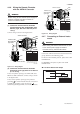
■ NORMAL OPERATING CONDITIONS
Ambient Temperature: –40°C to +60°C (–40°F to +140°F)
• Indicator’s operating range: –20°C to +60°C (–4°F to +140°F)
• Maximum temperature should be 50°C in the case of
power supply code 2.
Ambient Humidity: 0 to 100%
Lengthy continuous operation at 95% or more is not
recommended.
Power Supply
Power supply code 1:
• AC specifications
Rated power supply: 100 to 240 V AC, 50/60 Hz
(Operating voltage range: 80 to 264 V AC)
• DC specifications
Rated power supply: 100 to 120 V DC
(Operating voltage range: 90 to 130 V DC)
Power supply code 2:
• AC specifications
Rated power supply: 24 V AC, 50/60 Hz
(Operating voltage range: 20.4 to 28.8 V AC)
• DC specifications
Rated power supply: 24 V DC
(Operating voltage range: 20.4 to 28.8 V DC)
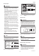
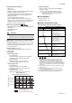
Supply Voltage and
Cable Length for Power Supply Code 2
0
20.4 22 24 26 28.8
200 ( 660)
446 (1460)
600 (1970)
796 (2610)
F04.EPS
Cable cross section area: 1.25 mm
2
Cable cross section area: 2 mm
2
Allowable cable length m(ft)
Usable range E (V)
Vibration Conditions:
Level of vibration in conformity with IEC 60068-2-6
(SAMA31. 1-1980)
9.8 m/s
2
or less (frequency of 500 Hz or less)
Note: Avoid locations with much vibration (with a vibration
frequency of 500 Hz or more), which may cause
damage to the equipment.
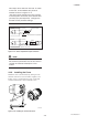
■ ACCESSORIES
Mounting bracket: 1 set
Hexagonal wrench: 1 pc.
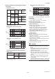
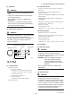
■ MODEL AND SUFFIX CODE
AXFA14 Magnetic Flowmeter Remote Converter:
Model Suffix Code Description
1 2 N
*1:
T03.EPS
G · · · · · · · · · · · · · · ·
C · · · · · · · · · · · · · · ·
-D · · · · · · · · · · · ·
-E · · · · · · · · · · · ·
-F · · · · · · · · · · · ·
-G · · · · · · · · · · · ·
1 · · · · · · · · ·
2 · · · · · · · · ·
1 · · · ·
2 · · · ·
N · · · ·
-0 · · · · · ·
-2 · · · · · ·
-4 · · · · · ·
4 to 20 mA DC, BRAIN Communication
4 to 20 mA DC, HART Communication
Digital communication
(F
OUNDATION
Fieldbus protocol)(*5)
Digital communication
(PROFIBUS PA protocol)(*6)
Magnetic Flowmeter Remote Converter
JIS G1/2 female
ANSI 1/2 NPT female
ISO M20 ⫻ 1.5 female
General-Purpose Use
For AXF Remote Flowtube of Size
2.5 to 400 mm (0.1 in. to 16 in.)
Explosion proof Type
For Remote Flowtube of Size 2.5 to
400 mm (0.1 in. to 16 in.)
100 V to 240 V AC or 100 to 120 V DC
24 V AC/DC
With Indicator (Horizontal)
With Indicator (Vertical)
None
/ⵧ
Optional code (See the Table of
Optional Specifications)
*2: For explosion proof types, specify type of explosion proof
certification using the optional codes. In case of the TIIS
flameproof type, the remote flowtube is available only for
combined use with the AXFA14. For the TIIS flameproof type
with wiring using a flameproof packing adapter, select optional
code G12 or G11. Available only for JIS G1/2 female electrical
connections.
*3: JIS G1/2 female electrical connection is available only for TIIS
flameproof type.
*4: In case of integral flowmeters of the TIIS flameproof type,
select “with indicator”(code 1 or 2).
*5: For F
OUNDATION
Fieldbus protocol, refer to IM 01E20F02-01E
*6:For PROFIBUS PA protocol, refer to IM 01E20F12-01E
AXFA14
Use (*2)
Output Signal and
Communication
Power Supply
Electrical Connections
(*3)
Indicator (*1)(*4)
Option
11-4