User’s Manual AXFA14G/C Magnetic Flowmeter Remote Converter [Hardware Edition/Software Edition] AXF Magnetic Flowmeter Integral Flowmeter [Software Edition] IM 01E20C02-01E IM 01E20C02-01E Yokogawa Electric Corporation 10th Edition
CONTENTS Contents 1. INTRODUCTION ................................................................................................... 1-1 1.1 1.2 1.3 1.4 2. HANDLING PRECAUTIONS ............................................................................... 2-1 2.1 2.2 2.3 2.4 3. Installation Location ........................................................................................ 3-1 Mounting .....................................................................................................
CONTENTS 6. PARAMETER DESCRIPTION ............................................................................ 6-1 6.1 6.2 6.3 6.4 Parameters ....................................................................................................... 6-1 Parameter Lists ................................................................................................ 6-1 Parameter List Overview ................................................................................ 6-2 Parameter Description ...........
CONTENTS 9. ACTUAL OPERATION ......................................................................................... 9-1 9.1 10. Pre-operation Zero Adjustment ....................................................................... 9-1 9.1.1 Zero Adjustment Using Display Unit Switches ....................................... 9-2 9.1.2 Zero Adjustment via External Status Input .............................................. 9-3 MAINTENANCE .................................................................
1. INTRODUCTION 1. INTRODUCTION This instrument has been adjusted at the factory before shipment. • Please note that this user's manual may not be revised for any specification changes, construction changes or operating part changes that are not considered to affect function or performance.
1. INTRODUCTION • All procedures relating to installation must comply with the electrical code of the country where it is used. (2) Wiring • The wiring of the magnetic flowmeter must be performed by expert engineer or skilled personnel. No operator shall be permitted to perform procedures relating to wiring. • When connecting the wiring, check that the supply voltage is within the range of the voltage specified for this instrument before connecting the power cable.
1. INTRODUCTION The guarantee will not apply in the following cases: • Damage due to negligence or insufficient maintenance on the part of the customer. • Problems or damage resulting from handling, operation or storage that violates the intended use and specifications. • Problems that result from using or performing maintenance on the instrument in a location that does not comply with the installation location specified by Yokogawa.
1. INTRODUCTION 1.4 ATEX Documentation SF This procedure is only applicable to the countries in European Union. Kaikkien ATEX Ex -tyyppisten tuotteiden käyttöhjeet ovat saatavilla englannin-, saksan- ja ranskankielisinä. Mikäli tarvitsette Ex -tyyppisten tuotteiden ohjeita omalla paikallisella kielellännne, ottakaa yhteyttä lähimpään Yokogawa-toimistoon tai -edustajaan. GB All instruction manuals for ATEX Ex related products are available in English, German and French.
1.
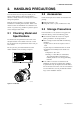
2. HANDLING PRECAUTIONS 2. HANDLING PRECAUTIONS This instrument has been inspected carefully at the factory before shipment. When the instrument is delivered, visually check that no damage has occurred during transportation. 2.2 Accessories Read this section carefully as it contains important information on handling this instrument. Refer to the relevant sections for information not contained in this section. If you have any problems or questions, please contact Yokogawa sales office.
2. HANDLING PRECAUTIONS 2.4 Installation Location Precautions Select the installation location with consideration to the following items to ensure long-term stable operation of the instrument. Ambient Temperature: Avoid installing the instrument in locations with constantly fluctuating temperatures. If the location is subject to radiant heat from the plant, provide heat insulation or improve ventilation. Atmospheric Condition: Avoid installing the instrument in a corrosive atmosphere.
3. INSTALLATION 3. INSTALLATION 1. Fix the instrument on the mounting fixture using four screws. WARNING Installation of the magnetic flowmeter must be performed by expert engineer or skilled personnel. No operator shall be permitted to perform procedures relating to installation. 2. Fix the mounting fixture with the instrument installed on a 2-inch pipe using a U-bolt. Horizontal Mounting 3.
4. WIRING 4. WIRING • Ground the remote flowtube and the converter separately. • Cover each shield of the signal cable with vinyl tube or vinyl tape to avoid contact between two shields or between a shield and a case. • When waterproof glands or union equipped waterproof glands are used, avoid tightening the glands with an excessive torque. • In case of 24V power supply version, it comes with a plug. Use this plug to cover the unused wiring port when wiring the instrument with only one, four-core cable.
4. WIRING Finished diameter: 10.5 mm (0.413") Maximum length: 100 m (330 ft) Maximum temperature: 80°C (176°F) NOTE Conductors A and B carry the signal from the electrodes, and C is at the potential of the liquid (signal common). Shields SA and SB are kept at the same potentials as the individual electrodes (these are actively driven shields.) This is done to reduce the effect of the distributed capacitance of the cable at long cable length.
4. WIRING NOTE • For excitation and power cables, always use a crimp terminal with an insulation cover. • Use crimp tools from the manufacturer of the crimp terminal you want to use to connect the crimp terminal and cable. • Use crimp tools that are appropriate for the diameter of the cable to be connected. Washer Gasket Waterproof gland 4.3 Wiring Ports Cable This instrument is of watertight construction as stipulated in JIS C0920.
4. WIRING 4.4.2 (3) Conduit Wiring When wiring the conduits, pass the conduit through the wiring connection port, and utilize the waterproof gland to prevent water from flowing in. Place the conduit pipe on an angle as shown in Figure 4.3.4. Install a drain valve at the low end of the vertical pipe, and open the valve regularly. Terminal Configuration When the cover is removed, the connection terminals will be visible. The terminal configuration labels are attached in the locations shown in Figure 4.4.
4. WIRING 4.4.3 Precautions for Wiring of Power Supply Cables 4.4.4 DC Power Connection When using DC power as the power supply for the converter, give attention to the following points. When connecting to the power supply, observe the points below. Failure to comply with these warnings may result in an electric shock or damage to the instrument. (1) Connecting Power Supply IMPORTANT Do not connect power supply with reversed polarities.
4. WIRING 4.4.6 4.4.5 Grounding CAUTION Wiring the Remote Flowtube with the AXFA14 Converter WARNING Be sure to connect the protective grounding of the AXFA14 with a cable of 2mm2 or larger cross section in oder to avoid electrical shock to the operators and maintenance engineers and to prevent the influence of external noise. Connect the grounding wire to the mark. The grounding should satisfy Class D requirements (ground resistance, 100 or less).
4. WIRING Pulse Output (2) Connection with the Remote Flowtube (Explosion proof Type, Size 2.5 to 400 mm (0.1 to 16 in.)) In case of explosion proof type for ATEX, FM, CSA, IECEx and TIIS certification, connect wiring as shown in the figure below. IMPORTANT • As this is a transistor contact (insulated type), give attention to proper voltage and polarity when wiring. • Do not apply a voltage larger than 30V DC or a current larger than 0.2A in order to prevent damage to the instrument.
4. WIRING AXFA14 PULSE OUT AXFA14 This output cannot switch an AC load. To switch an AC load, an intermediate relay must be inserted as shown in Figure 4.4.11. *The alarm output operates from open (normal) to closed (alarm occurrence) in the default value (as setup upon plant shipment). Changes can be made via the parameter settings. Protective diode DO+ Mechanical Counter DO- DO+ PULSE OUT DO- Load Electronic Counter Output voltage: 24 V DC 20% • Current: 150 mA or less Pulse rate: 0.
5. BASIC OPERATING PROCEDURES 5. BASIC OPERATING PROCEDURES (USING THE DISPLAY UNIT) The modification of data settings from the display unit can be carried out using the three setting switches (infra-red switches) - namely, the , , and switches. The infra-red switches enable the user to set parameters without opening the cover. This chapter will provide a description of basic data configuration and the methods to be used with the three setting switches.
5. BASIC OPERATING PROCEDURES 5.1 Operating Panel Configuration and Functions (4) Reversed character display (1) Data display area (3) Display items 100.000 0 3274m3 FR m3/h 100 FTL (1) Data display area 1st line (Display Select1), 2nd line (Display Select2), and 3rd line (Display Select3) can be displayed using parameter settings. The content corresponding to selected item is shown with the reversed-character on the right of the line.
5. BASIC OPERATING PROCEDURES 5.2 Display Unit Setting Methods NOTE Before changing any settings, be sure to check the corresponding setting details in Chapter 6: Parameter Description. 5.2.1 Display Mode → Setting Mode Display Mode will be adopted when the power is turned on, and the Setting Mode can be activated using the following procedure.
5. BASIC OPERATING PROCEDURES A screen is displayed to confirm whether or not the system is to enter Setting Mode. Setting Mode Press the switch and select [Yes]. No Yes The reversed-character (i.e. the cursor position) indicates the item that is currently selected. When [Yes] has been selected, touch the switch. Setting Mode NOTE No Yes When the operations except and switches are carried out, the system will automatically return to the Display Mode.
5. BASIC OPERATING PROCEDURES 5.2.2 Setting Mode When the Setting Mode has been activated using the procedure from Section 5.2.1, parameters can be selected for setting. NOTE If no operations are carried out for a period of 10 minutes in Setting Mode, the system will automatically return to the Display Mode. Format for Parameter Data Depending on the type of parameter, data is formatted in one of the following three ways.
5. BASIC OPERATING PROCEDURES Sub-item Parameter Search Mode Major item Sub-item parameter Sub-item Parameter Search Mode has been accessed in this screen. B:Easy Setup 50:Auto Zero Exe 10:Language 20:Flow Damping Touch the X2 Major item Sub-item selection (A) B21: Base Flow Unit. The cursor has been moved to B21: Base Flow Unit in this screen.
5. BASIC OPERATING PROCEDURES 5.3.2 Setting Example for Numeric-Type Data: Flow rate span This example describes the setting of the flow rate span for the numeric-type parameter B23: Flow Span from 100 l/min to 120 l/min. Start: Major Item Parameter Search Mode Setting mode Major item parameter Setting Mode Condition Setting Mode P:Protect B:Easy Setup C:Basic Setup Touch the switch to access B: Easy Setup.
5. BASIC OPERATING PROCEDURES When the switch is touched, the entire display flashes on and off. Confirm that the setting has been correctly changed to “120”, and then fix B23:Flow Span 120 l/min this value by touching the switch once again. NOTE When no operations are carried out for 20 seconds in the flashing state, the system will automatically return to the Sub-item Parameter Search Mode. When the operations except are carried out, the parameter cannot be set.
5. BASIC OPERATING PROCEDURES Sub-item Parameter Search Mode Major item Sub-item selection (C) Upon selection of C: Basic Setup, the cursor will be positioned at C10: Tag No. (Sub-item selection screen (C)) C:Basic Setup 49:Flow User Span 10:Tag No 11:Flow Damping Selection of the appropriate parameter Parameter Current setting value Replacement Mode Modified value The cursor will flash on and off on the left of the tag number.
6. PARAMETER DESCRIPTION 6. PARAMETER DESCRIPTION 6.1 Parameters NOTE In order to ensure that correct flow rate data can be acquired, it is crucial that the nominal size, flow rate span, and meter factor of the combined remote flowtube are set. In cases where a remote flowtube is ordered at the same time as the AXFA14, or where the AXF integral flowmeter is ordered, the nominal size and meter factor will be set upon shipment from the manufacturing plant, and these will not require additional setting.
6. PARAMETER DESCRIPTION 6.3 Parameter List Overview (1) Item A (Menu A): Display items Menu A contains the instantaneous flow rate, totalization values, and other items relevant to display. Name Item Display unit (BRAIN) Data range R/W Display unit /BRAIN Units Position Default value of decimal (*): Indicated item point Description A00 Display (DISPLAY) A10 FR (FLOW RATE (%)) A20 FR (FLOW RATE) R -110.0 to 110.
6. PARAMETER DESCRIPTION Name Item Display unit (BRAIN) Data range R/W Display unit /BRAIN Units Position Default value of decimal (*): Indicated item point Description B22 Base Time Unit (TIME UNIT) W /d /h /min /s B23 Flow Span (FLOW SPAN) W 0.
6. PARAMETER DESCRIPTION (3) Item C (Menu C): Basic Setting items Menu C principally contains the basic setting items for the flowtube. Name Item Display unit (BRAIN) Data range R/W Display unit /BRAIN Units Position Default value of decimal (*): Indicated item point Description C00 Basic Setup (BASIC SETUP) C10 Tag No (TAG NO) W ASCII 16 characters C11 Flow Damping (FLOW DAMPING) W 0.1 to 200.0 C20 Measure Mode (MEASURE MODE) C21 Low MF (LOW MF) W W Standard DF Enhanced DF 0.0100 to 3.
6. PARAMETER DESCRIPTION Name Item Display unit (BRAIN) Data range R/W C44 Velocity Check (VELOCITY CHK) R C45 Density Unit (DENSITY UNIT) W C46 Mass Flow Density (MASS DENSITY) C47 User Span Select (USER SPN SEL) C48 Flow User Unit (FL USER UNIT) C49 Flow User Span (FL USER SPAN) C60 — (SELF CHECK) W W W Display unit /BRAIN 0.000 to 99.
6. PARAMETER DESCRIPTION (5) Item E (Menu E): Pulse Setting items Menu E contains items relevant to pulse output. This is used to set parameters such as the pulse scale and width. Name Item Display unit (BRAIN) E00 Pulse Set (PULSE SET) E10 Pulse Unit (PULSE UNIT) Data range R/W Display unit /BRAIN W n Unit/P u Unit/P m Unit/P Unit/P k Unit/P M Unit/P Pulse/s E11 Pulse Scale (PULSE SCALE) W 0 to 32000 E12 Pulse Width (PULSE WIDTH) W E13 Pulse Low Cut (PULSE LOWCUT) W 50% Duty 0.05 ms 0.1ms 0.
6. PARAMETER DESCRIPTION Name Item Display unit (BRAIN) Data range R/W Display unit /BRAIN Units Position Default value of decimal (*): Indicated item point Description F22 DO Active Mode (DO ACT MODE) W Closed(On) Act Open(Off) Act Closed(On) Act Selects whether DO terminal will be set to “On Active” or “Off Active”.
6.
6. PARAMETER DESCRIPTION (8) Item H (Menu H): Display Setting items Menu H contains setting items that are relevant to display on the display unit.
6. PARAMETER DESCRIPTION Name Item Display unit (BRAIN) Data range R/W Display unit /BRAIN Units Position Default value of decimal (*): Indicated item point J30 Power Synch (POWER SYNCH) W J31 Power Frequency (POWER FREQ) R/W J40 Memo 1 (MEMO 1) J41 Memo 2 (MEMO 2) J42 Memo 3 (MEMO 3) J50 Software Rev No (SOFTWARE REV) W ASCII 16 characters Memo field W ASCII 16 characters Memo field W ASCII 16 characters Memo field R — Software revision number R Good Error See “6.
6. PARAMETER DESCRIPTION (12) Item N (Menu N): Loop Test Setting items Menu N contains items that are relevant to the execution of loop testing. Name Item Display unit (BRAIN) Data range R/W Display unit /BRAIN Units Position Default value of decimal (*): Indicated item point Description N00 Test (TEST) N10 Test Mode (TEST MODE) W Normal Test Normal Selects whether mode will be set to “Normal” or “Test”.
6. PARAMETER DESCRIPTION 6.4 Parameter Description [B22: Base Time Unit] Selection of time units for the flow rate span → This setting is linked with that of parameter C41. This parameter selects the time units for the flow rate span; however, if “m” has been selected for the flow rate units, “/s” is automatically set for this parameter. (1) Menu B: Easy Setup items Those parameters with a high frequency of use have been grouped together in Easy Setup.
6. PARAMETER DESCRIPTION number of 2 or greater for the next digit to the right, regardless of the position of the decimal point. Example: A value of 333.33 is represented by the character string 33333, and since this exceeds 32000, it cannot be set. In such a case, the value 333.3 should be set instead. Item Description n Unit/P 10-9 FU u Unit/P 10-6 FU m Unit/P 10-3 FU Unit/P FU k Unit/P 103 FU M Unit/P 106 FU Pulse/s Number of pulses to be counted for one second at 100% output.
6. PARAMETER DESCRIPTION Example 1: To count in 1 Ml (mega-liter) steps with flow rate span = 100 m3/h Since 1 Ml = 103 x m3, k Unit/P is set for B30/D10, and 1 is set for B31/D11. “x103 m3” is indicated for the totalized units in the Display Mode. Example 2: To count in 10 l (liter) steps with flow rate span = 100 m3/h Since 1 l = 10-3 x m3, m Unit/P is set for B30/D10, and 10 is set for B31/D11. “x10-2 m3” is indicated for the totalized units in the Display Mode.
6. PARAMETER DESCRIPTION B41/H11: Display Select2 and B42/H12: Display Select3 as described below. (For more details, refer to Chapter 5: Basic Operating Procedures.) remote flowtube is ordered at the same time as the AXFA14, or where the AXF integral flowmeter is ordered, the nominal size and meter factor will be set upon shipment from the manufacturing plant, and these will not require additional setting.
6. PARAMETER DESCRIPTION [C23: Low MF (EDF)] Setting of the low-frequency meter factor for EDF This parameter sets the low-frequency meter factor as required when Enhanced DF (i.e., enhanced dual frequency excitation) is selected. If “Standard DF” has been selected for C20: Measure Mode, neither C23: Low MF (EDF) nor C24: High MF (EDF) is displayed, and if “Enhanced DF” is selected, the four parameters from C21 to C24 will be displayed.
6. PARAMETER DESCRIPTION [C45: Density Unit] Setting of the density units for mass flow rate This parameter selects the units for density as required when making settings using C46: Mass Density. (3) Menu D: Total Setting items Menu D contains parameters that are relevant to totalization function settings. [C46: Mass Density] Setting of the density for mass flow rate This parameter is necessary in situations where t, kg, g, klb or lb has been selected as the mass unit in B21/ C40: Base Flow Unit.
6. PARAMETER DESCRIPTION [D20: Total Execution] Operation setting for the totalization function This parameter sets “Start” and “Stop” of the totalization function, in addition to performing the preset function for the forward totalized value and the reverse totalized value. *: The preset function starts the count for totalization from the set value.
6. PARAMETER DESCRIPTION (4) Menu E: Pulse Setting items Menu E contains items relevant to pulse output. [E13: Pulse Low Cut] Setting of the pulse output stop range This parameter allows the settings to be made which prevent pulse output when the flow rate is at or below the low-cut setting value. In cases where there are multiple ranges or forward/reverse ranges, low cut is carried out at the setting value for the smallest span (i.e., an integer between 0 and 10%).
6. PARAMETER DESCRIPTION (5) Menu F: Status Functions Setting items Menu F contains setting items relevant to status Input/Output functions. [F20: DO Function] Setting of the function for the DO status output terminal This parameter sets the function for the DO (status output) terminal. Setting Function Description No Function Stops output (i.e., inactive condition) As no function is set, there is no output. Pulse Output Pulse output Pulse output is carried out.
6. PARAMETER DESCRIPTION [F21: DIO Function] Setting of the function for the DIO status input/output terminal This parameter sets the function for the DIO (status input/output) terminal. Setting Function No Function No function Alarm Output Output upon alarm Description As no function is set, there is no input and output. Warning Output Output upon warning Refer to Alarms (Section 6.5).
6. PARAMETER DESCRIPTION [F22: DO Active Mode] Setting of the active mode for DO terminal Example 1: When the “Pulse Output” function is selected for the DO terminal and the E12: Pulse Width is “1 ms”, the following signals are output from the terminal. Operations are performed in accordance with the following table when the active mode has been set to “Closed (On) Act” using this parameter. Operating patterns are reversed when the active mode has been set to “Open (Off) Act.
6. PARAMETER DESCRIPTION Status Output for Automatic Multiple Ranges Switching Operations are performed in accordance with the following table when the active mode has been set to “Closed (On) Act” using F22: DO Active Mode or “Closed/Short Act” using F23: DIO Active Mode. Operating patterns are reversed when the active mode has been set to “Open (Off) Act” using F22: DO Active Mode or “Open/Open Act” using F23: DIO Active Mode.
6. PARAMETER DESCRIPTION Parameter setting sequence (for automatic multiple ranges switching) Output No. 1 range No. 2 range No. 3 range No. 4 range 100% F20: DO Function Select a function. F22: DO Active Mode Select whether DO output is to be “Closed (On) Act” or “Open (Off) Act”. F21: DIO Function Select a function. F23: DIO Active Mode Select whether DIO output is to be “Closed/Short Act” or “Open/Open Act”.
6. PARAMETER DESCRIPTION Multiple Ranges Setting 2: Multiple ranges switching via external status input For both the forward and reverse directions, switching of up to two ranges can be carried out based on a status input; however, switching between directions is not possible. Switching between forward and reverse ranges is carried out automatically only when the flow direction reverses. DIO terminal is used for multiple ranges switching. For more details, refer to Table 6.4.
6. PARAMETER DESCRIPTION (6) Menu G: Alarm Setting items (Refer to Section 6.5: Alarm Functions for more details.) Menu G principally contains setting items relevant to alarms. Output Example 1 The high-high alarm (HH) is set to 90% or more of the flow rate span; the low-low alarm (LL), to 20% or less; the high alarm (H), to 80% or more; and the low alarm (L), to 30% or less.
6. PARAMETER DESCRIPTION Output Example 2 The high alarm (H) is set to 80% or more of the flow rate span; the low-low alarm (LL), to 20% or less. Output Example 3 The high alarm (H) is set to 80% or more of the flow rate span; the high-high alarm (HH), to 90% or more.
6. PARAMETER DESCRIPTION [G14: H/L Alarm Hys] Setting of upper/lower alarm value hysteresis width This parameter sets the hysteresis width for upper and lower alarm value, using a % value of the maximum span. [G22: 4-20mA Burn Out] Display of the current output during a CPU failure This parameter displays the current output direction for a CPU failure (i.e., burnout). Note that communication will not be possible if such a failure occurs.
6. PARAMETER DESCRIPTION Alarm Items [G33: Alm-HH/LL] Alarm recognition of “HH/LL Alarm” (Refer to the descriptions of G12 and G13 for more details regarding HH and LL alarms.) This parameter specifies whether HH/LL alarm in process alarms will be recognized as an alarm. Setting Item (i.e.
6. PARAMETER DESCRIPTION [G45: Alm Record3] Alarm record3 This parameter is used to display the third most-recent alarm, and the alarms that can be displayed are the same as those for G41: Alm Record1. [H30: Language] Selection of language used for the display unit → Refer to the description for parameter B10 This parameter can be used to select the language for the display unit.
6. PARAMETER DESCRIPTION Note: This function does not apply to measurement in both the forward and reverse directions, although this can be setup using by selecting “Fwd/Rev Rngs(O)” from either F20: DO Function or F21: DIO Function. NOTE If “2.4mA or less” has been set for G21:4-20mA Alarm Out, 2.4mA or less will be output upon an alarm occurrence, regardless of the low limit setting. NOTE Setting Function Forward Forward direction corresponds with arrow mark.
6. PARAMETER DESCRIPTION Example 1: Step input [J24: T/P Damp Select] Setting of damping operation This parameter is used to select that the flow rate value obtained through damping calculation for totalization and pulse output or the instantaneous flow rate value (no damping) for totalization and pulse output. Input: 0 to 10% Damping time constant: 3 s Dead time: 3 s Rate limit value: 1% 10% Step signal Flow rate value after rate limit processing 1% (c) (b) (a) 100 Setting 63.
6. PARAMETER DESCRIPTION [J40: Memo 1] Setting of memo 1 [K11: Adhesion Level1] Setting the resistance value for adhesion diagnostic level1 This parameter sets the resistance value (in M ohm) for judgment of Level 1. [J41: Memo 2] Setting of memo 2 [J42: Memo 3] Setting of memo 3 These parameters are used with the memo function, and up to 16 characters can be set for each.
6. PARAMETER DESCRIPTION (11) Menu N: Loop Test Setting items Menu N contains items that are relevant to loop testing. [N31: Test DIO (O)] Setting for the DIO terminal condition during testing This parameter sets the condition of the DIO terminal during loop testing. Setting is possible when “Test” has been selected for N10: Test Mode. [N10: Test Mode] Setting for loop test execution Setting Function Normal No execution of loop testing. Test Loop testing is started Setting T0641.
6. PARAMETER DESCRIPTION [P23: Software Seal] Display the software seal When the joker password has been used to release write protection, this parameter displays “Break”, and when protection is cancelled using the password set using P22: New Password, it returns to “Keep”. Default setting (Enable) P20:Write Protect No F0617.EPS Write protection (Protect) NOTE P20:Write Protect Yes If you should forget your password, the joker password can be used to temporarily release write protection function.
6. PARAMETER DESCRIPTION 6.5.2 Alarm Selection [G30: Alm-Setting] Alarm recognition of “Setting Alarm” The display and output differs depending on the alarm levels. Certain types of alarm may or may not be recognized as alarms, according to the settings of certain parameters. The parameters that are relevant to this function as follows.
6. PARAMETER DESCRIPTION (3) Display and output condition for setting alarm occurrences Alarm description 50 Span > 10m/s Selection (parameter Alarm 4-20 mA Totalinumber) output output zation Span flow velocity setting is 11 m/s or more 52 TTL>10000p/s Totalization rate is 11000 pps or more 53 TTL<0.0001p/s Totalization rate is 0.00005 pps or less 54 4-20 Lmt Err 55 Multi Rng Err The condition [4-20 low limit (J11) < 4-20 high limit (J12)] is not satisfied. The condition [No. 1 range < No.
6. PARAMETER DESCRIPTION 6.5.3 Alarms & Warning Messages System Alarms (Device breakdown or inability to obtain correct measurements.
6. PARAMETER DESCRIPTION Setting Alarms (Device is normal but errors have been made in the setting of parameters.) Display unit/BRAIN ( 60) content Alarm countermeasure message on display unit Alarm description 50:Span > 10m/s Check parameter C40, C41, and C42 51:Span < 0.1m/s Check parameter C40, C41, and C42 52:TTL>10000p/s 53:TTL<0.
6. PARAMETER DESCRIPTION 6.
7. OPERATION VIA BRAIN TERMINAL (BT200) 7. OPERATION VIA BRAIN TERMINAL (BT200) 7.1.2 NOTE Key Descriptions (1) Alphanumeric keys and shift keys You can use the alphanumeric keys in conjunction with the shift keys to enter letters, digits, and symbols. This chapter describes the AXFA14 converter as an example. The same attention must be paid to the AXF integral flowmeter. 7.1 BT200 Basic Operations 7.1.1 Alphanumeric keys Key Layout and Display Shift keys F0703.
7. OPERATION VIA BRAIN TERMINAL (BT200) Function Command List Use the function key [F2] CAPS to select between uppercase and lowercase (for letters only). The case toggles between uppercase and lowercase each time you press [F2] CAPS. Command ADJ CAPS/caps Selects uppercase or lowercase CODE Entering uppercase CODE CAPS CLR Entering lowercase ESC Entry CODE caps CLR ESC Key-in Sequence to lower case (o) (y) F0807.
7. OPERATION VIA BRAIN TERMINAL (BT200) 7.2 AXFA14 Operation Using a BT200 Refer to Chapter 6 “Menu P: Parameter Protection Items” and section “10.2.2” how to use the write protect function in detail. This section describes procedures for setting parameters using a BRAIN Terminal (BT200). For more details regarding AXFA14 functions, refer to Chapter 6: Parameter Description; and for more details regarding BT200 operation methods, refer to the BT200 User’s Manual (IM 01C00A11-01E). 7.2.
7. OPERATION VIA BRAIN TERMINAL (BT200) (2) Upload/download function of BT200 Upload function is used when the parameters of one AXFA14 are copied to the BT200. And download function is used when the parameters copied to the BT200 are set to another AXFA14. For details, refer to BT200 User’s Manual (IM 01C00A11-01E). The targeted parameters for upload and download are following.
7. OPERATION VIA BRAIN TERMINAL (BT200) 7.3.1 BT200 Setting of Selection-Type Data: Flow rate units In this example, the flow rate units specified by the selection-type parameter B21: Flow Unit are changed from m3 to l (Liter).
7. OPERATION VIA BRAIN TERMINAL (BT200) 7.3.2 BT200 Setting of Numeric-Type Data: Flow rate span In this example, the flow rate span specified by the numeric-type parameter B23: Flow Span is changed from 100.000 l/min. to 120.000 l/m. MENU A:DISPLAY B:EASY SETUP C:BASIC SETUP D:TOTAL SET E:PULSE SET F:STATUS FUNC HOME SET ADJ MENU A:DISPLAY B:EASY SETUP C:BASIC SETUP D:TOTAL SET E:PULSE SET F:STATUS FUNC HOME SET ADJ SETTING B23:FLOW SPAN 100.
7. OPERATION VIA BRAIN TERMINAL (BT200) 7.3.3 BT200 Setting of Alphanumeric-Type Data: Tag number In this example, the tag number specified by the alphanumeric-type parameter C10: TAG NO is changed from “FI-1101” to “FI-1201”.
8. OPERATION VIA HART COMMUNICATOR 8. OPERATION VIA HART COMMUNICATOR 2. Confirmation of the device revision for the HART Configuration Tool NOTE This chapter describes the AXFA14 as an example. (1) Turn on the power of the Configuration Tool under the standalone condition. (2) Confirm the installed DD revision in accordance with the procedure of the Configuration Tool. Refer to its manual how to confirm it in detail.
8. OPERATION VIA HART COMMUNICATOR 8.2 Interconnection between AXFA14 and HART Configuration Tool The HART Configuration Tool can interface with the AXFA14 from the control room, the AXFA14 site, or any other wiring termination point in the loop, provided there is a minimum load resistance of 250 V between the connection and the receiving instrument. To communicate, it must be connected in parallel with the AXFA14, and the connections must be non-polarized. Figure 8.2.
8. OPERATION VIA HART COMMUNICATOR 8.3 Basic Setup 8.4 Parameters Tag and Device Information The tag number and device information can be checked as follows: 8.4.1 The parameter structure of the HART configuration tool is hierarchical. • The location for the tag number and device information Refer to 8.4.6, Menu Tree Example for the corresponding parameters. The menu tree shows a cross-reference of the parameters for HART and BRAIN.
8. OPERATION VIA HART COMMUNICATOR 8.4.3 Self-diagnostic If no error is detected, “Status: Normal” is displayed on the configuration tool. If the specific diagnostic item is known for the check, you can directly call up the item by using the Diagnostic List in the Device Status display. The Diagnostic List is categorized to Device Status, Hardware Failure, Transducer Status, Diag Status, and Configuration.
8. OPERATION VIA HART COMMUNICATOR Burst Mode AXFA14 continuously sends the data via HART communication when the burst mode is set on (any one of PV, % range/current, or process vars/crnt). The data is sent intermittently as a digital signal at 3 times a second. The burst mode is set as follows. IMPORTANT The D/A trim should be executed only at single range mode. If the D/A trim is executed at Bi direction mode, it is possible that the current output becomes 108%.
8. OPERATION VIA HART COMMUNICATOR (2) Activating the multidrop mode About the procedure to call up the Polling display, please refer to the User’s Manual of each configuration tool. NOTE When the same polling address is assigned for two or more field devices in multidrop mode, communication with these field devices is disabled. (3) Communication when set in the multidrop mode 1.
8. OPERATION VIA HART COMMUNICATOR 8.4.6 Menu Tree for DD (HART 5) Offline New Configuration Saved Configuration Online Frequency Utility 1. Device setup 2. PV 3. PV AO 4.
8.
8.
8. OPERATION VIA HART COMMUNICATOR 5 Review 1 Review1 2 Review2 3 Review3 4 Review4 Hot key 1 PV Span 2 Wrt Protect Menu 1 2 3 4 Write protect Enable Wrt 10min New Password Software Seal *1 : Data Renewing P : Periodic Date Renewing u/d : Discretionary Renewing – : Other (Method etc...) Read/Write Parameter of BRAIN protocol Data(*1) R R R R – – – – – – – – W B23/C42 u/d R W W R P20 P21 P22 P23 P – – – F0806.
8.
8. OPERATION VIA HART COMMUNICATOR 8.4.
8.
8.
8.
8. OPERATION VIA HART COMMUNICATOR F Calibration G Write Protect Parameter Data Read/Write of BRAIN Renewing (*1) protocol Auto Zero Exe Magflow Zero D/A trim Scaled D/A trim Write protect Enable Wrt Password New Password Software Seal – R/W – – M10/B50 M11 – – – – – – R W W R P20 P21 P22 P23 P – – – *1: Data Renewing P : Periodic Data Renewing u/d : Discretionary Data Renewing – : Others (Method, etc...) F0812.
9. ACTUAL OPERATION 9. ACTUAL OPERATION After you have installed the flowtube into the process piping, wired the input/output terminals, set up the required parameters, and performed a pre-operation zero adjustment, the magnetic flowmeter should output an accurate flow signal from its terminals as soon as flow of the fluid to be measured begins. This section describes zero adjustment and the corresponding procedures. For FOUNDATION Fieldbus protocol, please refer to IM 01E20F02-01E.
9. ACTUAL OPERATION 9.1.1 Zero Adjustment Using Display Unit Switches This section describes the procedure for zero adjustment using the display unit switches. (For more details regarding setting methods using these switches, refer to Chapter 5: Basic Operating Procedures.) The parameters for zero adjustment are B50/M10: Auto Zero Exe (and either of these can be used to carry out this procedure). For more details regarding these parameters, refer to Chapter 6: Parameter Description.
9. ACTUAL OPERATION Auto zero adjustment function is being executed (about 30 seconds). Now Auto Zero Executing... Sub-item Parameter Search Mode Major item Sub-item selection (D) M:Adjustment When zero adjustment function has been completed, the system automatically returns to the sub-item selection screen (D). 10:Auto Zero Exe 11:Magflow Zero F0901.EPS NOTE The results of M10: Auto Zero Exe can be displayed using M11: Magflow Zero.
9. ACTUAL OPERATION F21:DIO Function No Function No Function Alarm Output Parameter Replacement (execute) Mode Touch the switch twelve times to move the cursor to “Ext Auto Zero (I)”. X12 F21:DIO Function No Function Ext Auto Zero (I) Ext Ttl Preset (I) switch to select “Ext Auto Zero Touch the (Zero adjustment via external status input)”. In order to request confirmation, the entire display flashes on and off.
10. MAINTENANCE 10. MAINTENANCE 10.1.1 Fuse Replacement 10.1 Maintenance CAUTION WARNING Please contact Yokogawa's service office for fuse replacement. Also be sure to use the fuse that was supplied by Yokogawa’s sales or service offices. • Maintenance work must be carried out by the trained personnel having knowledge of safety standard and not by operators. • When opening the cover, wait for more than 10 minutes after turning off the power.
10. MAINTENANCE 10.1.2.2 Changing the Display Unit Direction 90 Degrees 10.1.2.3 Installing the Cover (1) Hold the display unit with your hand and remove the two mounting screws. (1) Taking care not to entangle the cables, install the cover to the flowmeter by turning it in the direction of the arrow as shown below. (2) Turn the display unit 90 degrees clockwise and confirm the assembling position, taking care of the connector and wire of the display unit. At this time, do not remove the connector.
10. MAINTENANCE 10.2 Setting of Switches Low Switch 1 Switch 2 Enable High 2 Burnout setting switch 1 Write protect setting switch Protect IMPORTANT • Removing and installing cover are necessary for setting switches. Perform removing and installing of the cover as described in section 10.1.2.1 and 10.1.2.3. • To preserve the safety, do not touch the electrical circuit and the cables except the setting switches. F1007.EPS Figure 10.2.1 Switch Configuration 10.2.
10. MAINTENANCE 10.3 Troubleshooting Although magnetic flowmeters rarely require maintenance, failures may occur when the instrument is not operated correctly. This section describes troubleshooting procedures where the cause of the breakdown is identified through receiver indication. 10.3.1 No Indication START Is an error being displayed? Check the converter display. Is an error being displayed? YES Examine in accordance with Section 6.5: Alarms.
10. MAINTENANCE 10.3.2 Unstable Zero START Investigate whether or not the flowtube is filled with fluid and that it is free of bubbles. *1: When checking for bubbles, it is convenient if there is a gas vent hole on the flowtube’s downstream side. *1 Is the flowtube completely full of fluid? NO Particular care must be taken in the case of horizontal mounting. In order to ensure complete filling of the tube, either adjust the mounting position or switch to vertical mounting.
10. MAINTENANCE 10.3.3 Disagreement Between Indication and Actual Flow START NO Are parameters set correctly? Set the parameters correctly. YES Examine the condition of the fluid in the flowtube, of bubbles, and of grounding. Was zero adjustment carried out correctly? Execute zero adjustment when the flowtube is filled completely with fluid and when the fluid is not moving.
11. OUTLINE 11. OUTLINE ■ STANDARD SPECIFICATIONS HART: Load Resistance: 250 to 600 Ω (including cable resistance) Refer to IM 01E20F02-01E for FOUNDATION Fieldbus communication type and IM 01E20F12-01E for PROFIBUS PA communication type marked with “ ” Note: HART is a registered trademark of the HART Communication Foundation. Converter Data Security During Power Failure: Data (parameters, totalizer value, etc.) storage by EEPROM. No back-up battery required.
11. OUTLINE Functions “ ” Forward and Reverse Flow Measurement Functions (*1)(*2): Flows in both forward and reverse directions can be measured. The reverse flow measurement can be confirmed by status output and indicator. How to Set Parameters (*2): The indicator’s LCD and three infra-red switches enable users to set parameters without opening the case cover. Parameters can also be set with the configuration tool (Such as HHT (handheld terminal) or FieldMate, etc.).
11. OUTLINE Accuracy (Combined with AXF Remote Flowtube) Size 25 mm (1.0 in.) to 400 mm (16 in.) % of Rate 1.2 Pulse Output: PFA/Ceramics Lining: 1.0 0.8 High grade Standard Size mm Flow Velocity Accuracy Flow Velocity Accuracy (in.) V m/s (ft/s) (Calibration V m/s (ft/s) (Calibration code B) code C) 2.5 (0.1) to 15 (0.5) V 0.3 (1) 1.0 mm/s — 0.3 V 10 0.35% of (1) (33) Rate V 0.15 (0.5) 0.5 mm/s 25 (1.0) to 0.15 V 10 0.35% of 200 (8.0) (0.5) (33) Rate 250 (10) to 400 (16) Pulse 0.
11. OUTLINE Safety Requirement Standards: EN61010-1 • Altitude at installation site: Max. 2000 m above sea level • Installation category based on IEC1010: Overvoltage category II (“II” applies to electrical equipment which is supplied from a fixed installation-like distribution board.) • Pollution degree based on IEC1010 Pollution degree 2 (“Pollution degree” describes the degree to which a solid, liquid, or gas which deteriorates dielectric strength or surface resistivity is adhering.
11. OUTLINE Signal Cable: Model AXFC Termination Cable Length Suffix Code ············· Description Magnetic Flowmeter Dedicated Signal cable for the ADMAG AXF series -0 · · · · · · · · · · · No Termination. -4 · · · · · · · · · · · A set of termination parts for M4 screws is attached. Terminated for the AXFA11/14 Remote Converter. -L · · · · · Option /C Designate the cable length, unit: m Following “L”, specify the cable in three digits as multiple of 1 meter (e.g.
11. OUTLINE ■ OPTIONAL SPECIFICATIONS FOR AXFA14 REMOTE CONVERTER “ ” : Available –: Not available Code D E AXF***C-F G Specification D E AXF***G-F G Item Applicable Model General- Explosion Purpose proof Type use Lightning Protector A lightning protector is built into the power terminals. A DC Noise Cut Circuit The DC Noise Cut Circuit is built in. Available for 15 mm (0.5 in.) and larger sizes, and for fluids with the conductivity of 50 µS/cm or higher.
11. OUTLINE Flameproof packing Four flameproof packing adapters adapter for TIIS Flameproof Type Three flameproof packing adapters and one blind plug. Available only when a four-wires cable is used for power input and signal output with DC power supply.
11. OUTLINE ■ EXTERNAL DIMENSIONS ● Remote Converter AXFA14G/C Unit: mm (approx. inch) Ground Terminal (M4) 243.5(9.59) 139.5(5.49) 57(2.24) 49(1.92) 180(7.09) ø128(5.04) 28 (1.1) 197(7.76)*1 66(2.6) 103(4.06) 31(1.22) ø87(3.43) *No infra-red switches are furnished for Fieldbus communication type. Weight: 2.8kg (6.2lb) *1: When indicator code N is selected, subtract 12 mm (0.47 inch) from the value in the figure. In case of explosion proof type with indicator, add 5 mm (0.2 inch) to it. F06.
11. OUTLINE ● Flameproof packing adapter for TIIS Flameproof type (optional code G14 or G13) T1 Unit : mm (Approx. inch) Adapter body(M. Screw) O-Ring Packing case 16.5(0.65) Hexagon socket set screw Packing * 18(0.71) Hexagon socket set screw O-Ring L F C O-Ring Washer G Union nut Packing gland *Packing (Choose from the table below depend on cable outside diameter) D Clamp ring Clamp nut T2 O-Ring B.
12. EXPLOSION PROTECTED TYPE INSTRUMENT 12. EXPLOSION PROTECTED TYPE INSTRUMENT 12.1 ATEX In this section, further requirements and differences for explosion proof type instrument are described. WARNING WARNING Only trained persons use this instrument in industrial locations. • Magnetic flowmeters with the model name AXFA14C are products which have been certified as explosion proof type instruments.
12. EXPLOSION PROTECTED TYPE INSTRUMENT (3) Installation CE: CE marking II 2G: Group II Category 2 Gas atmosphere II 1D: Group II Category 1 Dust atmosphere No.: KEMA 03ATEX2435: EC Type Examination certificate number EEx d IIC T6: Protection type and temp. class ENCLOSURE: Enclosure protection code WARNING • All wiring shall comply with local installation requirements and local electrical code.
12. EXPLOSION PROTECTED TYPE INSTRUMENT For CSA C22.2 Series Explosion proof for Class I, Division 1, Groups A, B, C & D. Dust-ignition proof for Class II/III, Division 1, Groups E, F & G. “SEAL ALL CONDUITS WITHIN 50 cm OF THE ENCLOSURE” “WHEN INSTALLED IN DIV. 2, SEALS NOT REQUIRED” (3) Operation WARNING • “OPEN CIRCUIT BEFORE REMOVING COVERS.” • “SEAL ALL CONDUITS WITHIN 18 INCHES” in hazardous locations.
12. EXPLOSION PROTECTED TYPE INSTRUMENT (3) Operation 12.4 IECEx For CSA C22.2 Series WARNING WARNING WARNING : OPEN CIRCUIT BEFORE REMOVING COVER. OUVRIR LE CIRCUIT AVANT D’ENLEVER LE COUVERCLE. • Take care not to generate mechanical spark when access to the instrument and peripheral devices in hazardous location. Only trained persons use this instrument in industrial locations.
12. EXPLOSION PROTECTED TYPE INSTRUMENT (3) Operation less) or JIS Class A(grounding resistance 10 or less) WARNING • After de-energizing, delay 20 minutes before opening. • Take care not to generate mechanical spark when access to the instrument and peripheral devices in hazardous locations. WARNING In case that ambient temperature exceeds 50°C, use heat-resistant cables with maximum allowable temperature of 70°C or above.
12. EXPLOSION PROTECTED TYPE INSTRUMENT • Apply a nonhardening sealant to the terminal box connection port and to the threads on the flameproof packing adapter for waterproofing. • The same wiring as described below is required for all of the terminal box connection ports except when a four-wire cable is used for power input and signal output with DC power supply. Proper tightening is important.
INSTALLATION AND OPERATING PRECAUTIONS FOR TIIS FLAMEPROOF EQUIPMENT INSTALLATION AND OPERATING PRECAUTIONS FOR TIIS FLAMEPROOF EQUIPMENT Apparatus Certified Under Technical Criteria (IEC-compatible Standards) 1. General tion is of completely enclosed type and its enclosure shall endure explosive pressures in cases where explosive gases or vapours entering the enclosure cause explosion.
INSTALLATION AND OPERATING PRECAUTIONS FOR TIIS FLAMEPROOF EQUIPMENT 4. Installation of Flameproof Apparatus • Specific cables shall be used as recommended by the “USER’S GUIDELINES for Electrical Installations for Explosive Gas Atmospheres in General Industry,” published in 1994. • In necessary, appropriate protective pipes (conduit or flexible pipes), ducts or trays shall be used for preventing the cable run (outside the cable glands) from damage.
INSTALLATION AND OPERATING PRECAUTIONS FOR TIIS FLAMEPROOF EQUIPMENT 6. Maintenance of Flameproof Apparatus that the apparatus must always be restored to its original condition). If you attempt to repair the flameproof apparatus, company-specified components shall be used. (d) Before starting to service the apparatus, be sure to check all parts necessary for retaining the requirements for flameproof apparatus.
REVISION RECORD Title: AXFA14G/C Magnetic Flowmeter Remote Converter [Hardware Edition/Software Edition] AXF Magnetic Flowmeter Integral Flowmeter [Software Edition] Manual No.: IM 01E20C02-01E Edition Date Page 6th Oct. 2005 6-3 to 6-7 6.3 11-3 11-7 12-4 SF2 12.4 7th June 2006 1-1 4-4 4-7 4-7 5-1 7-3 8-1 10-3 10-4 Revised Item 4.4.2 4.4.6 (2) 4.4.7 7.2.1 10.1.3 10.2.1 10.2.2 11-1,2 11-4 to 8 11-5 8th May 2007 1-2 1-3 1-5 4-3 4-5 (4) 1.3 1.4 4.3 4.4.4 5-1 5-3 5.
Edition Date 9th Jan. 2008 Page Revised Item 1-1 Added the postscript about PROFIBUS PA protocol type. 1-2 1.1 4-4 4.4.2 Added the warning note on "write protect". 4-7 4.4.7 Added the postscript about PROFIBUS PA protocol type. 5-1 5 Added the postscript about FOUNDATION Fieldbus protocol type and PROFIBUS PA protocol type. 6-1 6.1 7-3 7.2.1 Added the postscript about PROFIBUS PA protocol type. Added the warning note on "write protect".
Edition Date Page 10th June 2012 1-3 Revised Item Added the "Trademarks". 2-1 2.2 Deleted the fuse from item of accessories. 4-2 (2) Added the recomended cable. 4-3 4.3 Deleted the sentence of JIS C0920 standard. Corrected the Figure 4.3.1 and added two washers. Corrected the Figure 4.3.3 and added a gasket. 4-8 4.4.7 5-1 5 5-4 6-11 P23 B33 6-29 G40, G42 7.2 7.2.1 7-4 Added the explanatory sentence of infra-red switches. Corrected the figures.