
User Manual
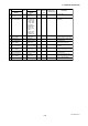

IM 01E20C02-01E
6-7
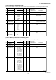
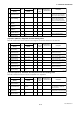
6. PARAMETER DESCRIPTION
T0607-2.EPS
Item
Name
Display unit
(BRAIN)
Data range
Display unit
/BRAIN
Default value
(*): Indicated item
Units
R/W
Position
of decimal
point
Description
0 to 4
0 to 4
00 to 15 %Auto Range Hys
(AUTO RNG HYS)
0 to 4
0 to 4
Reverse Span1
(REV SPAN1)
Forward Span4
(FWD SPAN4)
Forward Span3
(FWD SPAN3)
Reverse Span2
(REV SPAN2)
DIO Active Mode
(DIO ACT MODE)
Forward Span2
(FWD SPAN2)
DO Active Mode
(DO ACT MODE)
W Closed(On) Act
Open(Off) Act
0 to 4
C40
/C41
C40
/C41
0.0001 to 32000
C40
/C41
0.0001 to 32000 C40
/C41
0.0001 to 32000
0.0001 to 32000
0.0001 to 32000
W
W
W
C40
/C41
W
W
W
Closed/Short Act
Open/Open Act
W
Sets flow rate span for reverse
No. 2 range
—
(SELF CHECK)
RF60 Good
Error
F41
F32
F34
F40
F33
Sets flow rate span for forward
No. 2 range
Sets flow rate span for forward
No. 3 range
Selects whether DIO terminal
will be set to “Closed/Short
Active” or“Open/Open Active”.
Sets flow rate span for forward
No. 4 range
Sets hysteresis width for
forward/reverse switching
See “6.5 Alarm Function”.
Bi Direction Hys
(BI DIREC HYS)
Sets hysteresis width for
automatic range switching
Sets flow rate span for reverse
No. 1 range
1
2 %
F31
1
1
0 to 8 0W %
10 %
F22
F23
F30
1
Selects whether DO terminal
will be set to “On Active” or
“Off Active”.
Closed/Short Act
1
Closed(On) Act
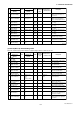
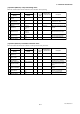
(7) Item G (Menu G): Alarm Setting items
Menu G contains setting items relevant to alarm output, burnout, alarm record, etc.
T0608-1.EPS
Item
Name
Display unit
(BRAIN)
Data range
Display unit
/BRAIN
Default value
(*): Indicated item
Units
R/W
Position
of decimal
point
Description
0
0
R
W
W
W
No
Yes
0
0
Low Alarm
(LOW ALARM)
Low Low Alarm
(LO LO ALARM)
High Alarm
(HIGH ALARM)
H/L Alarm Hys
(H/L ALM HYS)
High High Alarm
(HI HI ALARM)
Alarm
(ALARM)
0
No
Yes
2.4mA or Less
4.0mA
Hold
21.6mA or More
4-20mA Alarm Out
(4-20 ALM OUT)
High
Low
No
Yes
-110 to 110
-110 to 110
W
-110 to 110
0 to 10
W
W
W
W
-110 to 110
W
%
%
%
%
%
Selects whether an electrode
adhesion alarm
is to be specified
as an alarm.
G34
G33
Alm-Adhesion
(ALM-ADHESION)
No
Yes
G32
W
G31
G21
G13
G14
4-20mA Burn Out
(4-20 BURNOUT)
G22
Selects the current output during
alarm occurrence.
Sets level setting value for high-
high flow rate limit (HH)
Sets hysteresis width for high-
low flow rate limit alarm
G12
Sets level setting value for high
flow rate limit (H)
Displays the current output
during a CPU failure.
Sets level setting value for low-
low flow rate limit (LL)
Selects whether a flow rate high-
high or low-low alarm is to be
specified as an alarm.
No
Selects whether an empty pipe
alarm is to be specified as an alarm.
Selects whether a signal overflow
alarm is to be specified as an alarm.
Selects whether a setting alarm is
to be specified as an alarm.
G30 Yes
NoNo
Yes
Yes
Yes
W
Alm-Sig Over
(ALM-SIG OVER)
Alm-Setting
(ALM-SETTING)
Alm-Emp Pipe
(ALM-EMP PIPE)
Alm-HH/LL
(ALM-HH/LL)
Sets level setting value for low
flow rate limit (L)
G11
-110
G00
—
G10
21.6mA or
More
110
5 %
-110
110