
User Manual

IM 01E20C02-01E
6-31
6. PARAMETER DESCRIPTION
NOTE
If “2.4mA or less” has been set for G21:4-20mA
Alarm Out, 2.4mA or less will be output upon an
alarm occurrence, regardless of the low limit
setting.
NOTE
• If the setting value for the low limit is not less
than the high limit value (as set using J12: 4-
20mA High Lmt), the setting alarm “54: 4-20
Lmt Err” will be displayed.
• This parameter has no effect on pulse output
or the totalization function.
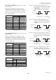
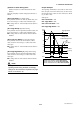
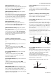
[J12: 4-20mA High Lmt] Setting of the high limit
for current output
This parameter is used to restrict high current portions
of current (4 to 20mA) output, and it is initially set to
120%. Setting should be performed when a lower value
is required for the higher limit.
The indications of the instantaneous flow rates (%,
Actual instantaneous flow rate, mA, Bar graph) on the
display unit are the same action.
Example: Situation where high limit is set to 90%
F0656.EPS
4mA
Output
Input
18.4mA(90%)
NOTE
If “21.6mA or more” has been set for G21:4-20
mA Alarm Out, 21.6mA or more will be output
upon an alarm occurrence, regardless of the
high limit setting.
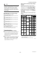
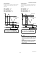
[J20: Flow Direction] Setting of the flow direction
Upon shipment from the manufacturing plant, the
system is setup such that flow in the same direction, as
shown by the direction of the arrow mark on the
flowtube, will be measured as forward flow; however,
this parameter can be used to set “Reverse” so that
flow in the opposite direction to the arrow mark will be
treated as forward.
Note: This function does not apply to measurement in
both the forward and reverse directions, al-
though this can be setup using by selecting
“Fwd/Rev Rngs(O)” from either F20: DO
Function or F21: DIO Function.
Setting Function
Forward direction corresponds with arrow mark.
Forward direction is opposite to arrow mark.
Forward
Reverse
T0638.EPS
[J21: Rate Limit] Setting of the rate limit value
This parameter is used in situations where sudden
noise cannot be eliminated by increasing the
damping time constant.
In situations where step signals or sudden noise
signals caused by slurries or the like are entered, this
parameter is used to set the standard for determining
whether an input corresponds to a flow measurement
or noise. Specifically, this determination is made
using upper and lower rate limits and using the dead
time.
Rate limit values are set using a percentage of the
smallest range. The range of deviation per one
calculation cycle should be input.
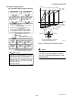
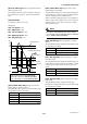
[J22: Dead Time] Setting of dead time
This parameter sets the time for application of the rate
limit, and if a value of 0 is set, the rate limit function
will be terminated.
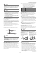
NOTE
Determining rate limit value and dead time
F0613.EPS
T0
T0
2%
2%
Rate limit value:
Determines the level for output
fluctuation cutoff. For example,
if this is set to 2%, noise above
2% will be eliminated as shown
in the diagram.
Dead time (T
0
):
This is to be determined using the
output fluctuation width. If noise
exceeds the dead time as shown in
the diagram below, the dead time
should be made longer.
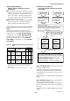
Signal processing method:
A fixed upper and lower limit value is setup with
respect to the primary delay response value for the
flow rate value obtained during the previous sam-
pling, and if the currently sampled flow rate is
outside these limits, then the corresponding limit is
adopted as the current flow rate value. In addition, if
signals which breach the limits in the same direction
occur over multiple samples (i.e., within the dead
time), it is concluded that the corresponding signal is
a flow rate signal.