
User Manual

IM 01E20C02-01E
8-5
8. OPERATION VIA HART COMMUNICATOR
IMPORTANT
The D/A trim should be executed only at single
range mode. If the D/A trim is executed at Bi
direction mode, it is possible that the current
output becomes 108%.
IMPORTANT
When “D/A trim” or “Scaled D/A trim” is carried
out, the warning message “83: Fix Cur Wng” is
displayed on the display unit.
CAUTION
The output adjustment function can match the
4mA and 20mA output to the reference meter
such as a voltmeter. In the output adjustment, it
is necessary to use the calibrated voltmeter and
resistance.
Fixed Current Output
This feature can be used to output a fixed current for
loop checks.
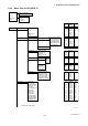
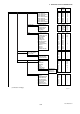
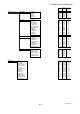
In the case of using DD
Call up the test output parameter (Loop test) and select
the output signal.
• Procedure to call up the display
DD Device Setup → Diagnosis/Service →
Test → Loop test →
→ 4mA Output a 4mA DC signal
→ 20mA Output a 20mA DC signal
→ Other Set a desired output signal value
→ End Exit
T0806.EPS
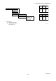
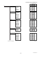
In the case of using DTM
Call up the test output parameter (Loop test) and select
either manual test or auto test, and set the current
value.
• Procedure to call up the display
DTM Diag and Service → Output Test →
Loop test →
→ Manual Test Set the current value or % value at
Test output value, then click the Start
button.
→ Auto Test Set the interval and rate of change of
current output at Auto Test Setting,
then click the Start button.
T0807.EPS
Burst Mode
AXFA14 continuously sends the data via HART
communication when the burst mode is set on (any one
of PV, % range/current, or process vars/crnt). The data
is sent intermittently as a digital signal at 3 times a
second.
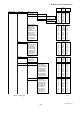
The burst mode is set as follows.
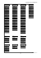
(1) Setting the data to be sent
• Procedure to call up the display
DD Device Setup → Detailed setup
→ HART output → Burst option
DTM Confi guration → HART → Burst option
T0810.EPS
Select the type of data to be sent from the following
options:
- Instantaneous flow rate (PV)
- Output in % and current output (% range/current)
- Instantaneous flow rate, totalization value* and
current output (Process vars/crnt)
* “Totl,” “Reverse Totl” or “Dif Totl”
(2) Setting the burst mode
• Procedure to call up the display
DD Device Setup → Detailed setup →
HART output → Burst mode
DTM Confi guration → HART → Burst mode
T0811.EPS
Then, select “On” at the menu to start the burst
mode.
To release from the burst mode, call up the burst
mode display, and set to “Off.”
The default setting is “Off.”
Multidrop Mode
When set in the multidrop mode, up to 15 field devices
in a single communications line can be connected. To
activate multidrop communication, the address of the
field devices must be set to a number from 1 to 15.
This deactivates the 4 to 20 mA analog output, fixing it
to 4 mA. Burn out is also disabled.
Note that the accuracy for multidrop mode is different
from that for other modes. Refer to Chapter 11:
Outline.
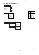
The multidrop mode is set as follows.
(1) Setting the polling address
• Procedure to call up the display
DD (HART 5) Device Setup → Detailed setup →
Output condition → HART output →
DTM (HART 5) Confi guration → HART →
→ Poll addr Enter the number from 1 to 15
T0812.EPS