
Manual

Please read this user’s manual thoroughly to ensure correct use of the
instrument. Carefully store this manual for future reference.
1. Cautionary Notes for Safe Use of the Products
The following symbol is indicated on the instrument and in this manual to
ensure safe use.
This symbol is indicated where the operator must refer to instructions
in the manual in order to protect both personnel and the instrument.
This symbol on the product indicates that the operator must refer to
an explanation in the user’s manual in order to avoid the risk of injury
or death of personnel and damage to the instrument. The manual
describes how the operator should exercise special care to avoid
electric shock or other dangers that may in injury or loss of life.
The purpose of the following conventional symbol in this manual is:
NOTE
Draws attention to information essential for understanding the
operation and features.
2.
Handling Precautions and Installation Location
N
OTE
● Note that these current transformers are designed for use with
general-purpose instruments and have not yet gained any official
certification. They cannot therefore be used for the purpose of
ascertaining wattage or other electric parameters.
● Use each current transformers under a load no greater than its
rated level. When calculating the load, you must calculate the
sum of the load given by the instruments to be connected to the
transformer and the load given by the lead-wire of the
secondary-stage cable.
● The inner-walls of the clamp are treated with rust preventive. But
if rusted, remove the rust with CRC-5-56 (goods on the market)
and spray rust preventive on the inner-walls again for recovery.
Avoid installing the current transformers in locations subject to:
ambient temperatures outside the specified range of -20 °C to 50 °C, where
condensation is likely; ambient humidity exceeding 80 % RH, where
condensation is likely; relatively large amounts of flammable or explosive
gas, saline substance, lampblack or dust; splashes of water, oil or solvent;
radioactive rays or intense electric or magnetic fields; frequent mechanical
vibration or shock; or direct sunlight.
3. Installation
W
ARNING
Since there is a risk of electric shock during installation, be sure to
observe the following.
● Before connecting the transformer to any other equipment, make
sure the circuit is not receiving any power in order to prevent
electric shock.
● Fasten the connecting terminals securely so they will not loosen
readily.
● Do not touch the terminals or any other part of the transformer
when the circuit is live.
● Do not use the transformer under a circuit current greater than
the level specified for that model.
● Do not use the transformer under a circuit voltage greater than
500 V AC.
N
OTE
The CTW contains a device for suppressing hazardous voltages that
ay arise when the secondary line is open-circuited. m
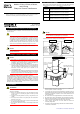
Install the transformer referring to the following figures.
Cable
Power-source side
K
Load side
L
Secondary-stage cable
k side = white; l side = black
Buckle
Tape for fixing the
current transformer
(accessory)
Example of Installation
①
Pull the buckle
in the direction
of the arrow.
①
How to Remove
Hook
①Hook the buckle.
②
Push the
buckle in the
direction of
the arrow
until it clicks.
②
①
How to Install
● Attach the transformer to the cable according to the orientation of the
K and L symbols, as shown in the figure.
● Cut the tape for fixing the current transformer (accessory) into the
appropriate length and wind the tape around the cable until the cable
becomes the thickness required to fit the inside diameter of the
current transformer.
● Be careful not to make a gap between the inner-walls of the clamp.
● Be careful not to trap any dust between the inner-walls of the clamp.
● Make sure the wound tape is not caught between the flat parts of the
clamp, and then securely fasten the clamp using the buckle.
● Use a crimp-on terminal for 0.75 mm
2
cables to connect the
secondary-stage cable.
● The wires of the secondary-stage cable are color-coded as follows.
k side=white; l side=black
IM 77C01W02-01E
2nd Edition: Jun. 2004
User’s
Manual
Cross-check the Model
Make sure the model and suffix codes shown on the data plate attached to
the transformer are the same as specified in your purchase order.
Models Names
CTW10
Clamp-on Current Transformer (for 100 A / 1 A)
Applicable cable diameter: less than
Φ
24 mm
CTW20
Clamp-on Current Transformer (for 200 A / 1 A)
Applicable cable diameter: less than
Φ
24 mm
CTW100
Clamp-on Current Transformer (for 500 A / 5 A)
Applicable cable diameter: less than
Φ
36 mm
CTW130
Clamp-on Current Transformer (for 800 A / 5 A)
Applicable cable diameter: less than
Φ
36 mm
Models CTW10, CTW20, CTW100,
and CTW130
Clamp-on Current Transformers
IM 77C01W02-01E 2nd Edition: 2004.06.01-00
1