Instruction Manual DA100 Data Acquisition Unit Communication Interface IM DA100-11E IM DA100-11E 6th Edition
Introduction This GP-IB/RS-232-C Interface User’s Manual describes the functions and commands of the optional GP-IB, RS-232-C, RS-422-A/RS-485, and ethernet interfaces. Read athis manual carefully before using these interface functions, and be sure to keep this manual on hand for future reference should any problems arise. As manuals relative to the DA100 data acquisition system, the following manuals are also provided. Read them if necessary. Name of manuals Manual No.
Configuration and Use of This Manual Configuration This user’s manual is composed of chapter 1 to chapter 8, an appendix, and indices. Chapter 1 Overview and Specifications of GP-IB Interface Describes the functions and specifications of the GP-IB interface and the address setting method. Chapter 2 Overview and Specifications of RS-232-C Interface Describes the functions and specifications of the RS-232-C interface and the parameter setting method.
TABLE OF CONTENTS 1 INTRODUCTION ................................................................................................................................................................... 1 CONFIGURATION AND USE OF THIS MANUAL ................................................................................................... 2 2 CHAPTER 1 OVERVIEW AND SPECIFICATIONS OF GP-IB INTERFACE 1.1 1.2 1.3 Description of Functions (GP-IB) .................................................................
TABLE OF CONTENTS 6.2 6.
TABLE OF CONTENTS APPENDIX Appendix1 Computing Equation ....................................................................................................................... App-1 Appendix2 Report Function .............................................................................................................................. App-5 1 Index ................................................................................................................................................................
1.1 Description of Functions (GP-IB) 1 Listener Function This allows almost all settings except power on/off and operation control. • Settings except communication settings. • Operation control except power on/off.
1.1 Description of Functions Status Byte Format The format of status byte output in serial polling is as follows: Upper-level byte 0 Lower-level byte 0 0 Interrupt generated at the end of A/D conversion. Interrupt generated at the time of syntax error. Interrupt generated when the internal timer is being operated or hourly, daily and monthly reports are created.(Optinal) Interrupt generated when measurement release is generated while computation is in progress (with computation functions).
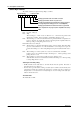
1.2 Setting of Address of GP-IB Interface 1 CDE AB 4 56 789 789 Rotary switch with which address is to be set IM DA100-11E 4 56 23 CDE AB 23 F0 1 F0 1 Address is the numeral to which the arrow is pointed 1-3 Overview and Specifications of GP-IB Interface The GP-IB address is set with the rotary switch located on the side of the GP-IB module connector. Turn the arrow on the rotary switch with a flat-blade screwdriver or the like to align the arrow with the address to be set.
1.
2.1 Description of Functions (RS-232-C) Listener and Talker Functions Data Output When trigger(GET) becomes activated DA100 will store the new data in a buffer. When an output request such as the FM command is received, these new data will be output. IM DA100-11E 2-1 2 Overview and Specifications of RS-232-C Interface Listener Function This allows almost all settings except power on/off and operation control. • Settings except communication settings. • Operation control except power on/off.
2.1 Description of Functions Commands Applicable to RS-232-C Only The following commands are only applicable to RS-232-C. ESC T Trigger execution [Syntax] ESC T [Description] Before sending this command, select output data by TS command. Data selected by TS command will be prepared for output and output will be executed using the FM, LF, CF, RF or VF command. ESC S Status byte output command [Syntax] ESC S [Description] The status of the corresponding command will be output.
2.2 Electrical & mechanical specs Connection format Communication format Synchronizing format : : : : Baud rate (bps) START bit Data length Parity STOP bit Connector Hardware handshake Software handshake Reception buffer length Escape sequence : : : : : ; : : : : Conform to the EIA RS-232-C Standard. Point-to point Half duplex Start-stop asynchronous transmission (synchronized by start/stop bit) 150, 300, 600, 1200, 2400, 4800, 9600, 19200, 38400 1 bit, fixed. Either 7 or 8 bits (selectable).
2.3 RS-232-C Interface Connection When connecting this instrument to a personal computer, first it is necessary to match settings such as handshake format, data transmission speed, and data format at the computer’s side. For details relating to these settings, refer to the description on this and following pages. Furthermore, make sure to use an interface cable which matches this instrument’s specifications. Connector and Signal Names 2 3 4 5 20 7 Numeric values in the above figure indicate Pin Nos. 2.
2.3 RS-232-C Interface Connection RS-232-C Signal List and Corresponding JIS & CCITT Abbreviation Signal Table Abbreviation Pin No.
2.4 Handshake Format Selection In order to ensure proper data transfers between the recorder and the host computer via the RS-232C interface, a mutual procedure is required for processing the electrical signals. Such a procedure is referred to as a ‘handshake’. Several handshake formats are available, with selection depending on the host computer being used. The same handshake format must be designated for both the recorder and the host computer.
2.4 Handshake Format Selection XON-DTR • Transmission data control • Reception data control • Reception data control CTS-DTR • Transmission data control • Reception data control IM DA100-11E : A hardware handshake status is established between the recorder and the host computer. The recorder will stop a data transmission if a ‘CTS=False’ status is established, and will resume the transmission when a ‘CTS=True’ status is established.
2.5 Communication Data Format The RS-232-C interface uses a START-STOP communication format. With this format, a START bit is placed at the beginning of each character transmitted, followed by the data bits, parity bit, and stop bit, in that order. (See the figure below.) ‘Line idle’ condition Return to ‘line idle’ condition (dotted line), or proceed to next data START bit.
2.6 RS-232-C Interface Parameter Setting Procedure Setting of the RS-232-C parameters must be carried out using the 3 dipswitches located next to the module connector. 1 2 Parameter setting switch 2 1 2 Parameter setting switch 3 1 2 3 4 Data length Baud rate 3 4 ON OFF Baud rate Stop bit Parity 3 4 ON OFF Not use Handshake system Baud rate (Switch No.1 to 3 of parameter setting switch 1 and Switch No.4 of parameter setting switch 2) Baud rate No.1 No.2 No.3 No.
3.1 Description of Functions (RS-422-A/RS-485) Listener and Talker Functions Listener Function This allows almost all settings except power on/off and operation control. • Settings except communication settings. • Operation control except power on/off. • Call-up of setting data • Specifying of output data (specifying of channel numbers or output data types) 3 Data Output When trigger(GET) becomes activated DA100 will store the new data in a buffer.
3.
3.3 RS-422-A/RS-485 Interface Connection The following explains how the RS-422-A/RS-485 module is connected to the computer.
3.3 RS-422-A/RS-485 Interface Connection Connecting to the Host Computer Can be connected to a host computer with RS-232-C, RS-422-A, RS-485 ports. • In the case of RS-232-C, a converter is used as shown in the diagram below. • For information on recommended converters, refer to “Converters” in the latter. • Dip switch needs to be changed depending on whether it is a two-wire system or four-wire system. Refer to “3.5 RS-422-A/RS-485 Interface Parameter Setting Procedure.
3.3 RS-422-A/RS-485 Interface Connection In the case of two-wire system Connect send and receive terminals with the same signal polarity on the terminal arrangement of the RS-422-A/RS-485 module. Only two wires are used in connecting to other units.
3.3 RS-422-A/RS-485 Interface Connection Converter Recommended converter : Sharp Z-101HE Caution Some converters other than the recommended, do not have the FG and SG terminals insulated. In such cases, do not connect as in the diagram on the previous page (do not connect anything to the FG and SG terminals of the converter). Especially when it is long distance, the potential difference may damage the devices or the communication may become unreliable.
3.3 RS-422-A/RS-485 Interface Connection Minimum Response Time Because send and receive are done on the same line in the two-wire system, minimum response time needs to be set. The minimum response time is the amount of time the RS-422-A/RS-485 module waits in order for the host computer to be able to receive the data after it sends data. The time can be set in the range from 0 to 100 ms.
3.4 Communication Data Format Same as the RS-232-C interface. For a description, refer to “2.5 Communication Data Format.
3.5 RS-422-A/RS-485 Interface Parameter Setting Procedure Setting of the RS-422-A/RS-485 parameters must be carried out using the 4 dip switches located next to the module connector. SW1 1 2 3 4 ON OFF Data length Baud rate 1 2 3 4 ON OFF four-wire/two-wire Stop bit Parity SW3 1 2 3 4 ON OFF Address (upper) Minimum response time SW4 1 2 3 4 ON OFF Address (lower) Baud rate (No.1 to 3 of SW1) Baud rate No.1 No.2 No.
3.5 RS-422-A/RS-485 Interface Parameter Setting Procedure Minimum response time (No.1 to 3 of SW3) Minimum response time No.1 No.2 No.3 0ms 10ms 20ms 50ms 100ms OFF OFF OFF OFF ON OFF OFF ON ON OFF OFF ON OFF ON OFF ← Default Setting Address (No.4 of SW3 and No.1 to 4 of SW4) 3-10 Address No.4(SW3) No.1(SW4) No.2(SW4) No.3(SW4) No.
4.1 Introduction of Functions (Ethernet) Connecting to the Network The Ethernet Module DT300-41 can connect to a network conforming to IEEE802.3 through a 10BASE-T. By connecting to a network, a PC also connected to the same network will be able to read the data measured by the DA100. However, to do so, the PC must have the following application software installed.
4.1 Introduction of Functions Communication Operation The flow of the communication is indicated below.
4.2 Specifications Communication Specifications Transmission specifications : 10BASE-T (CSMA/CD, 10Mbps, Baseband) Electrical/Mechanical specifications: Conforms to IEEE802.3 (Frames are not supported.) Protocols : TCP, IP, UDP, ARP, ICMP When supporting RS-232-C commands Communication format Keepalive When reading in instantaneous value data Communication format Keepalive : TCP/IP : Turn ON/OFF using dip switch 3.
4.3 Names and Functions of Each Section Dip Switch Tx (yellow) ) LINK (yellow) ON Status Indicator LED STS1 (green) OFF 1 2 3 4 STS2 (green) 10BASE-T Port Connect the RJ-45 modular jack of the twist pair cable connected to the 10BASE-T network. Setting the Dip Switch You can select the following three modes by setting the dip switch. Configuration mode: A mode in which the IP address, subnet mask, and default gateway are set for theDA100.
4.3 Names and Functions of Each Section Warning If the STS2 LED is lit, there is a problem with the communication. You can check the details of the problem by displaying the communication status (see section 4.8 “Displaying the Communication Information”). Error An error occurs when the communication fails. When communication error or EEPROM error occurs, the DA100 must be repaired.
4.4 Setting the IP Address Before connecting to the network, you will set the IP address, subnet mask, and default gateway of the DA100. You will need the Data Acquisition Software 32 that came with the DA100 or the Data Acquisition Software 32 Plus that is sold separately. Connect the PC and the DA100 as shown below. The PC must have the Data Acquisition Software 32 or the Data Acquisition Software 32 Plus installed. Set the mode of the Ethernet module to configuration mode.
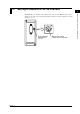
4.5 Connection Methods When Directly Connecting to the PC If you are directly connecting the DA100 and the PC to read in the measured data, connect them through a hub as follows. Ethernet module DC100 SCSI SUB UNIT I/F PC WARNING 100-240V AC 50/60Hz 130VA MAX FUSE 250V/T2.5A ETHERNET I/F 10BASE-T 4 MODEL STYLE SUFFIX Overview and Specifications of Ethernet Interface SUPPLY FREQUENCY NO.
4.6 Checking the Connection (Loopback test) Automatically tests the condition of the physical connection of the DA100 to the network. Mode Setting Set the dip switch of the Ethernet module to test mode (switch 1: OFF, switch 2: ON). Functions of the Ethernet module are suspended while in test mode. Therefore, it’s necessary to set the dip switch to communication mode after testing. Note • After testing, set the dip switch to communication mode and reboot the DA100.
4.7 Transferring the Instantaneous Values The instantaneous values of the data measured on the DA100 (current measured data) are transmitted to the PC that is connected through port No. 34151. Note • Up to four PCs can connect to port No. 34151 of one DA100. • The commands described here do not affect the status byte. • EF, EL, and EB commands do not suport sub-delimiters. The measured data are transmitted using the following command.
4.7 Transferring the Instantaneous Values The alarm status indicates two levels with one byte. Upper Byte Lower Byte Level2 Level1 1 byte Lower Byte Upper Byte Level4 Level3 1 byte D1 to Dn, H1 to Hn: Alarm status (level 3, 4) (No output when p1 is 0) Contents and format are the same as level 1 and 2. E1 to En: Fixed to 80H F1 to Fn: Computation channel number The measured/computed data are output in the order specified by the EB command.
4.8 Displaying the Communication Information The following information can be displayed by using Telnet. • Warning information • Connection information • Network information • The timeout for the information display application is 15 minutes. The operating procedures on Windows 95 Telnet are shown below. 1. Set the mode of the Ethernet module to communication mode and connect the DA100 and the PC. 2. Start the Telnet application that comes with Windows 95. 3.
4.8 Displaying the Communication Information 7. Enter any of the following commands to display the various information. wlog: Warning information con: Connection information net: Network information quit: Terminate the information display and disconnect the connection If you are using UNIX, follow the directions below. 1. telnet 133.140.1.1 34159 Port DA100's IP address or telnet open 133.140.1.1 34159 Port DA100's IP address 2.
4.9 Setting the Timeout A PC connected to the DA100 for a certain period of time is automatically disconnected. ET Mode Syntax p1 4 Note • The timeout set with the ET command is used for disconnecting a PC that stays connected for a certain period of time without any operation. KeepAlive is used for disconnecting a connection when the physical connection with the PC is disconnected or the PC goes down. • ET command does not support sub-delimiters.
5.1 Command Format • Channel number A channel number ..................... 3 characters Range of channel numbers ....... 6 characters AAA-BB For details of channel numbers, see page 5-4. Note • If the same setting is to be done for subsequent channels, it can be achieved by connecting channels with a “-” (minus sign). However, channels that can be set subsequently are effective only in the same unit.
5.1 Command Format Terminator Any one of the following forms a terminator. • CR + LF • LF • EOI = True (If EOI is to be used for a terminator, add EOI = True to the last parameter character.) Sub-delimita Several commands can be executed in a row when they are divided by a semicolon (;). Example XA2, 2, 0.5 ; XV4 ; XI2, AUTO CrLf Note • The total data length from the first character to the terminator should not exceed 200 bytes.
5.2 Command Syntax In this manual, each command is explained as shown below. Command function Command SD Set date & time. Effective command mode Command syntax Mode Set Parameter description Example of setting Ex. Explanation of the way to Comments use and remarks in more detail Operation mode SDp1, p2 p1 year, month, day p2 hour, min., sec. Set the clock inside the DA to July 1, ’96, 13:00:00 SD96/07/01, 13:00:00 • The formats of p1 and p2 are fixed to 8 characters.
5.3 Setting a Channel No., and Alarm Output Relay No. Channel and relay numbers are expressed as shown below in three characters. Unit No. + Slot No. + Number in slot 12 3 Channel/relay No. Slot No. (In case of channel/relay No. 10, Slot No. + 1) Unit No. ("A" for optional computation channel) Channel Number Stand-alone model(DA100-1) Expandable model(DA100-2) Unit No. 0 0 to 5 (Subunit: DS400/DS600) Slot No. 0 to 5 0 to 5 Channel No.
5.
5.5 Input Range Parameter DC Voltage Input Nominal Parameter input format Setting range 20mV 60mV 200mV 2V 6V 20V 50V 20mV 60mV 200mV 2V 6V 20V 50V –20.000 to 20.000mV –60.00 to 60.00mV –200.00 to 200.00mV –2.0000 to 2.0000V –6.000 to 6.000V –20.000 to 20.000V –50.00 to 50.00V Parameter input format Setting range Thermocouple Nominal R R S S B*1 B K K E E J J T T N N W W L L U U KpAu7Fe KP *1: Accuracy compensation range Type-B 0.0 to 1760.0°C 0.0 to 1760.0°C 0.0 to 1820.0°C –200.0 to 1370.
5.5 Input Range Parameter Contact Nominal Parameter input format VOLT LEVL CONTACT CONT *1: Less than 2.4 V → Off (0), 2.4 V or more → On (1) *2: Contact On (1), Contact Off (0) Setting range 0 to 1*1 0 to 1*2 DC Current Input Nominal Parameter input format Setting range 20mA 20mA -20.000 to +20.000mA Power Monitor Input range Nominal Parameter input format Setting range 25V-0.5A 25V-5A 250V-0.5A 250V-.5A 25V-0.5A 25V-5A 250V-0.5A 250V-5A 25VAC, 0.5A 25VAC, 5A 250VAC, 0.
5.
5.
5.6 ASCII Code Table 0 0 1 2 3 SP 0 4 5 6 7 1 A Q a q 2 2 B R b r 3 C S c s 4 D T d t # 4 5 % 5 E U e u 6 & 6 F V f v 7 G W g w 7 8 ( 8 H X h x 9 ) 9 I Y i y * : J Z j z + ; K k L l – M m E .
6.1 Setting Command 6.1 SR Setting Command The input mode changes to the mode before the reference channel was changed. • Set the span in p4 and p5 within the setting range for the reference channel shown on pages 5-6 and 5-7. • For p4 and p5 setting value, enter them within 6 digits excluding the decimal point. The decimal point is fixed. Refer to setting range on pages 5-6 and 5-7. • The measurement range cannot be changed while executing a report or computation. Sets the range.
6.1 Setting Command Setting the strain input Setting Example Comments SRp1, p2, p3, p4, p5 p1 Channel number (001 to 560) p2 STRAIN p3 Measurement range 2k/20k/200k p4 Left value of span p5 Right value of span Set the measurement range of subunit 1 and channel 01 to 20k, left value of span to 0, and right value of span to 100. SR101, STRAIN, 20k, 0, 100 • Even when the settings of p3 are the same parameters, the measurement range of the strain varies depending on the gauge method.
6.1 Setting Command • The measurement range cannot be changed while executing a report or computation. dL RH Setting the strain input scaling Setting Example Comments Sets the scaling unit. Mode Setting Example Comments SA Operation mode SNp1, p2 p1 Channel number (001 to 560) Computation channel number (A01-A60) p2 Unit character string (up to 6 characters) Set the scaling unit of subunit 0, channel 01 to ABCDEF.
6.1 Setting Command • Setting the output relay number of a module that is not connected to p5 causes an error. For the method to specify the relay number, see page 5-4. • Hysteresis should be set using the XA command. • The computation channel hysteresis is fixed to 0. • The optional computation channel number for a stand-alone model is A01 to A30. SD However, channels that can be set successively are effective only in the same subunit.
6.1 Setting Command SL Sets an event/action. Mode Operation mode Release of event/action setting Setting SLp1, p2 p1 event/action box number (01 to 30) p2 NONE Event action setting by an alarm Setting Example Comments SO Sets the computational expression.
6.1 Setting Command CM Sets communication input data. Mode Setting Example Comments RO Example Comments Mode Setting 6-6 Example Comments Setting hourly/daily/monthly report to ON/OFF and the time to create the report Mode Setting RM Operation mode CMp1, p2 p1 Communication input data number: Stand-alone model : C01 to C30 Expandable model : C01 to C60 P2 Numeric value: -32000 to 32000 Set 300 to the communication input data number C10.
6.1 Setting Command Integration time: Equivalent to 50/60 Hz Input module Filter off Filter on 10CH 0.5* 3 20CH 2 4 30CH 2 4 *: 2s if the power monitor module is installed Integration time: 100 ms Input module Filter off Filter on 10CH 4 12 20CH 5 15 30CH 6 20 XI p2 Example Comments Sets the A/D integration time. Mode Setting Example XQ XD Sets energizing or deenergizing. Mode Setting Sets the filter.
6.1 Setting Command XJ Selection of reference junction compensation Mode Setting Example Comments XG VS Selects the relay that can be turned ON/ OFF externally. Mode Setting Sets computation error handling.
6.1 Setting Command E0Cr+Lf: The processing of a received command has completed normally. E1Cr+Lf: There is an error in the received command. • After executing the command, the clock is initialized to 96/01/01, 00:00:00.
6.2 Control Execution Command Example Comments p4 Storage selection (ABORT, STORE) Store the calibrated values for the module in slot 1 of subunit 0. XZ0, 1, END, STORE • Connection DC Voltage Measurement : Input a DC voltage according to the measurement range to CH3. CH2 is short-circuit. Temperature Measurement using RTD : Input 100Ω to CH5. CH4 is short-circuit. • Caribrate the high sensitive RTD after calibrating of 60mV and 200mV ranges.
6.2 Control Execution Command • If initial balancing is executed, number-ofchannels worth of data are returned in the following format. S1 S2 CCC DDCrLf S1: Data status 1 N: Normal S: SKIP S2: Data status 2 Space: Data in the middle E: Data at the end CCC: Channel number DD: Result of the initial balancing OK: Initial balancing succeeded NG: Initial balancing failed DF: Default values set _: Skip module DR Example Comments Example Comments Transfers the setting mode.
6.3 Data Output Request Command If p2 is set to OFF, the relays with the setting parameters of 1 are turned OFF, and those of 0 maintain the current condition. • Always set p3 with four characters. • The settings of bits 11 to 16 of p3 are ignored. For the four-point alarm output relay module, bits 5 to 16 are ignored. 6.3 TS Data Output Request Command Selects the output data. Mode Setting Comments FM Selects the output format for measured data.
6.3 Data Output Request Command • If the daily report is to be output using extended format, the extended information must be output within 1 hour from the creation of the report. If the monthly report is to be output using extended format, the extended information must be output within 1 day from the creation of the report. After that, the extended information can not be output. • If there is no valid data within the specified report channel range, "FFFFH" is output.
7.
7.
7.
7.
7.
7.6 Output Format for Unit and Decimal Point Position These outputs are issued in the following format by the TS2 + “Device Trigger (GET)” + LF command. S1S2CCCUUUUUU, PCrLf Each symbol denotes the following: S1: Data status 1 N --------------------- Normal D --------------------- Differential input S ---------------------- Measurement range skips.
7.7 System Configuration Output Format The measurement interval and system connection data are output in the following format by the TS5 + “Device Trigger (GET)” + CF command: M : sssssCrLf S1 : 0=MMMMMM(DD)1=MMMMMM(DD)~5=MMMMMM(DD)CrLf Slot number Note • The number and data of subunits not connected in the system settings are not output.
7.8 A/D Calibration Data Output Format A/D calibration data are output in the following format by the TS8 + “Device Trigger (GET)” + LF command: This is effective only in the A/D calibration mode. XZ A/D calibration data for the first slot CrLf XZ EN A/D calibration data for the last slot Output completion CrLf CrLf Calibration data are output for every slot after the command to execute A/D calibration. The output format is the same form as in the XZ command setting shown below.
7.9 Report Output Format Hourly report The hourly report is output in the following format with the command, TS4+device trigger(GET)+RF0.
7.9 Report Output Format Data status Outputs the status of the report computation result. The sum of the top numbers of the phenomena from the following items is output. 1H: Detected over-limit data during measurement 2H: Detected special data during sampling 4H: Power failure occurred during computation 80H: Numerical data valid Output data Depending on the type of report computation, the results are output in the following order.
7.9 Report Output Format Daily Report The daily report is output in the following format with the command, TS4+device trigger(GET)+RF1.
7.9 Report Output Format Extended format for the daily report If the daily report is set to ON2, extended daily report is output in the following format with the command, TS4+device trigger(GET)+RF1.
7.9 Report Output Format Monthly Report The monthly report is output in the following format with the command, TS4+device trigger(GET)+RF2.
7.9 Report Output Format Extended format for the monthly report If the monthly report is set to ON2, extended daily report is output in the following format with the command, TS4+device trigger(GET)+RF2.
7.9 Report Output Format Status output of hourly/daily/monthly report The status of the hourly/daily/monthly report is output in the following format with the command, TS4+device trigger(GET)+RF3.
7.
8.1 GP-IB Sample Programs This section describes sampl eprogram for a system using PC 9801 series (NEC) with National Instruments GP-IB. Sample programs in this manual are writen in N88-BASIC(Standard language for PC9801 series). We hope that these samples will aid you in creating your own program. GP-IB Adress ALL the sample programs given in this chapter use adress 1 for DA100.
8.1 GP-IB Sample Programs Output the Unit and Decimal Point Data Read out the unit and decimal point data from DA100, display them on CRT of personal computer, and save them to floppy disk. 10 20 30 40 50 60 70 80 90 100 110 120 130 'TS2 LF OPEN "TS2.
8.1 GP-IB Sample Programs Output the measurement data (BINARY Code) Read out the measurement data by BINARY code from DA100, display on CRT of personal computer, and save to floppy disc. 10 20 30 40 50 60 70 80 90 100 110 120 130 140 150 160 170 180 190 200 210 220 230 240 250 260 'TS0 BO1 FM1 OPEN "TS0BIN.
8.2 RS-232-C Sample Programs This section describes sampl eprogram for a system using PC 9801 series (NEC) with the RS-232C interface. Sample programs in this manual are writen in N88-BASIC(Standard language for PC9801 series). We hope that these samples will aid you in creating your own program. Setting the RS-232-C Parameter In this sample program,the RS-232-C parameter settings are as shown below.
8.2 RS-232-C Sample Programs Output the Unit and Decimal Point Data Read out the unit and decimal point data from DA100, display them on CRT of personal computer, and save them to floppy disk. 10 20 30 40 50 60 70 80 90 100 110 120 'TS2 LF OPEN "COM1:E81N" AS #1 OPEN "TS2.
8.2 RS-232-C Sample Programs Output the measurement data (BINARY Code) Read out the measurement data by BINARY code from DA100, display on CRT of personal computer, and save to floppy disc. 10 20 30 40 50 60 70 80 90 100 110 120 130 140 150 160 170 180 190 200 210 220 230 240 250 260 270 'TS0 BO1 FM1 OPEN "COM1:E81N" AS #1 OPEN "TS0BIN.
8.3 RS-422-A/RS-485 Sample Programs This section describes sample program for a system using PC9801 series (NEC) with the RS-422-A/ RS-485 interface. We hope that these samples will aid you in creating your own program. Configuration Model Language Wiring system : NEC PC9801 series : N88-BASIC (Standard programming language on the PC9801 series) : four-wire system (both four-wire and two-wire systems are introduced in this manual for the ASCII output of the measured data).
8.3 RS-422-A/RS-485 Sample Programs Write the Setting Data to DA100 Read out the setting data from floppy disk, display them on CRT of the personal computer, and write them to DA100. 10 20 30 40 50 60 70 80 90 100 110 120 130 140 150 160 170 180 ‘ OPEN “COM1:E81N” AS #1 OPEN “TS1.
8.3 RS-422-A/RS-485 Sample Programs Output the Measurement Data (ASCII Code, four-wire) Read out the measurement data by ASCII code from DA100, display on CRT of the personal computer, and save to floppy disk. 10 20 30 40 50 60 70 80 90 100 110 120 130 140 150 160 170 180 190 200 ‘ OPEN “COM1:E81N” AS #1 OPEN “TS0ASC.
8.3 RS-422-A/RS-485 Sample Programs Output the Measurement Data (ASCII Code, two-wire) Read out the measurement data by ASCII code from DA100, display on CRT of the personal computer, and save to floppy disk. 10 20 30 40 50 60 70 80 90 100 110 120 130 140 150 160 170 180 190 200 210 220 230 240 250 260 270 280 290 300 310 320 330 340 350 360 370 ‘ OPEN “COM1:E81N” AS #1 OPEN “TS0ASC.
8.3 RS-422-A/RS-485 Sample Programs Output the Measurement Data (Binary Code) Read out the measurement data by BINARY code from DA100, display on CRT of the personal computer, and save to floppy disk. IM DA100-11E ‘ OPEN “COM1:E81N” AS #1 OPEN “TS0BIN.
8.3 RS-422-A/RS-485 Sample Programs Output the System Configuration Data Read out the configuration data from DA100, display on CRT of the personal computer, and save to floppy disk. 10 20 30 40 50 60 70 80 90 100 110 120 130 140 150 160 170 180 190 200 8-12 ‘ OPEN “COM1:E81N” AS #1 OPEN “TS5.
8.4 Ethernet Program Configuration Model IBM PC/AT OS Windows95 Lnguage Visual-C Output the measurement data (ASCI) IM DA100-11E /* * DARWIN - PC Communication Program for Winsock */ #include #include #include #define IP_ADDR #define PORT_NUM #define BUF_MAX “133.140.104.
8.
App.1 Computing Equation DA100 can execute computations with the measured data of each input channel taken as a variable, and the results can be displayed/saved (functions available for use only when DA100 has the /M1 option) . The following operators can be used for computation. Basic operators Type Operator Example Description Addition + 001+002 Obtain the sum of the measured data of channel 001 and channel 002.
App.1 Computing Equation Statistical operators within the group Type Operator Example Description Maximum value CLOG.MAX() CLOG.MAX(G01) Obtain the maximum value of the measured data of group G01. Minimum value CLOG.MIN() CLOG.MIN(G02) Obtain the minimum value of the measured data of group G02. Max-min value CLOG.P-P() CLOG.P-P(G03) Total value CLOG.SUM() CLOG.SUM(G04) Obtain the total value of the measured data of group G04. Average value CLOG.AVE() CLOG.
App.1 Computing Equation Priority of operators The priority of operators in a computing equation is as follows. The operators are placed in order from the highest priority. Type Operators Function ABS(), SQR(), LOG(), LN(), EXP(), MAX(), MIN(), P-P(), SUM(), AVE(), PRE(), HOLD():, RESET(): Exponentiation ** Signs, logical negation +, -, NOT Multiplication, division *, / Addition, subtraction +, - Greater/less relation .GT., .LT., .GE., .LE. Equal/not equal relation .EQ., .NE.
App.1 Computing Equation - Control using the event/action function Can start/stop computations or clear/reset computed results by an event occurring. This function distinguishes clear and reset as shown below. - Clear Computed data When issued during the computation, the measured data is reset before doing the first computation.
App. 2 Report Function The DA calculates and processes an hour’s, day’s or month’s worth of measurement or computation data into instantaneous values, averages and/or sums. The results can be delivered using the communication function. Reports come in the following three types. • Hourly report Intervals Between Making Reports; Every hour (1:00, 2:00 . . .
App.2 Report Function Report Channels There are sixty report channels, from R01 to R60. You can assign channels for measuring objects being computed or computation channels and the type of computing on a report-channel basis. When making a report of computed data, let computing start before letting the report making start.
App.2 Report Function Starting/Stopping Report Making Report making can be started or stopped in two ways: • DR command • Use the event/action functions to define the start/stop of making a report for the following events: Edge action: You can define every event as an edge action to start/stop report making. Level action: You can use remote, alarm, relay signals as events to start/stop report making. Report making starts at the same time that any of these events occur.
App.2 Report Function Processing Against Absence of Measurement Measurement may not take place if the DA is loaded beyond its processing capability. If absence of measurement occurs, the DA compensates for the missing data with the data it measures immediately after recovering from the absence of measurement (the data for the period with no measurement thus match those acquired immediately after recovering from the absence of measurement).
Index A Page A/D calibration E Page established content of the setup mode setting ........................... 6-8 execution ............................................................................... 6-9 Ethernet data output format ................................................................. 7-8 connection ............................................................................. 4-7 mode ......................................................................................
Index math ........................................................................................... 6-5 S Page measurement period .................................................................. 6-6 scaling ........................................................................................ 6-2 measured data output format(ASCII code) ................................................... 7-2 serial polling ..............................................................................