User’s Manual DA100 Data Acquisition Unit IM DA100-01E IM DA100-01E 8th Edition
Foreword Thank you for purchasing the YOKOGAWA DA100 Data Acquisition System (DA100/DS400/ DS600). This User’s Manual contains useful information regarding the instrument’s functions and operating procedures, as well as precautions that should be observed during use. To ensure proper use of the instrument, please read this manual thoroughly before operating it. Keep the manual in a safe place for quick reference whenever a question arises.
About the Style Number Products with style numbers S6, S7, and S9 are not sold.
Checking the Contents of the Package Unpack the box and check the contents before operating the instrument. In case the wrong instrument or accessories have been delivered, or if some accessories are not present, or if they seem abnormal, contact the dealer from which you purchased them. Futhermore, please contact a Yokogawa representative to order any of parts as follows. Main Unit DA100 Check that model and suffix code given on the name plate are according to your order.
Checking the Contents of the Package Input Modules Check that model code given on the name plate is according to your order.
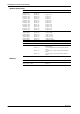
Checking the Contents of the Package Standard Accessories 1 power cord (conform your order) 1 3.5" floppy disk 1 clamp filter (Part No.
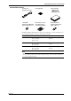
Checking the Contents of the Package Optional Accessories Name Model Description Extender module Extender base Extension cable Extension cable Extension cable Extension cable Extension cable Extension cable Extension cable Extension cable Extension cable Extension cable Extension cable Extension cable DV100-011 DV100-012 DV200-000 DV200-001 DV200-002 DV200-005 DV200-010 DV200-020 DV200-050 DV200-100 DV200-200 DV200-300 DV200-400 DV200-500 Length: 0.
Safety Precautions This instrument is an IEC safety class I instrument (provided with terminal for protective grounding). The following general safety precautions must be observed during all phases of operation, service and repair of this instrument. If this instrument is used in a manner not sepecified in this manual, the protection provided by this instrument may be impaired. Also, YOKOGAWA Electric Corporation assumes no liability for the customer’s failure to comply with these requirements.
How to Use this Manual This User’s Manual consists of the following four chapters and an Index. Chapter Title Description Chapter 1 System configuration Explains the position of the DA100 system within DARWIN, its configuration, functions, etc.. Chapter 2 Installation and Wiring Explains how to install and wire the DA100. Chapter 3 Trouble-shooting and Maintenance Explains how to analyse troubles and what to do in case trouble occurs.
Contents Foreword ............................................................................................................................................................................. 1 Checking the Contents of the Package ..................................................................................................................... 3 Safety Precautions ..............................................................................................................................................
1.1 About DARWIN Personal computer D CH=001 RANGE=TC TYPE-T Hybrid Recorder 001 002 003 004 005 006 007 008 009 010 DA100 DR230 011 012 013 014 015 016 017 018 019 020 021 022 023 024 025 026 027 028 029 030 DR240 Subunit Input/output modules FD Extension cables (max.
1.2 DA100’s System Configuration The DA100 is a data acquisition unit which allows data logging on a personal computer of small scale, 10-ch data logging up to 300-ch, multi-point measurements. Measurement data can be analyzed in real-time on the PC, as the DA100 can be controlled using communication interface. There are two types of DA100, the DA100 stand-alone type, and the DA100 expandable type.
1.
1.
1.
1.
1.
1.
1.
1.
1.4 Supportive Software for the DA100 System DAQ Software 32 (standard accessory) 1 System Configuration This software comprises functions such as setting of measurement conditions, diagnosis, calibration and simple data collection. The following three OS environments are supported. • Windows 95 • Windows 98 • Windows NT 4.
2.1 General Precautions for Installation Safety Precautions Read the safety precautions Make sure to have read the safety precautions described on pages 6 and 7 before using the instrument for the first time. Do not remove any covers from the instrument For internal inspection or adjustment, contact your sales representative or nearest service center. Addresses may be found on the back cover of this manual.
2.2 How to Install the DA100 Installation Conditions The instrument must be installed in a location where the following conditions are met. · Ambient temperature: 0 to 50 °C However, in case you mount the subunits DS400/DS600 directly to a panel, or mount them in a rack, it is possible to use them in a range of –10 to 60 °C. WARNING • When the environmental temperature is 50°C or more, the temperature of the rear panel may rise to more than 70°C.
2.2 How to Install the DA100 Panel installation Install the unit by fastening the accessory 6 screws (length : 16mm) as shown in the figure below. M4 Screws M4 Screws 2 Name Part No. Description Rack mount fittings DV400-011 ANSI/EIA standard Installation and Wiring Rack mounting The following metal fittings can be purchased for rack mounting. For installation, refer to the instruction manual which comes with the rack mount fittings.
2.3 How to Connect the Input/Output Modules WARNING When connecting the Input/Output modules, make sure to turn OFF the power to the DA100/DS400/DS600 to prevent an electric shock or damage to the instrument. Setting the Unit Number of each Subunit (only for the DA100 Expandable type) When connecting subunits to the DA100 Expandable type, it is necessary to assign a distinctive unit-number to each subunit.
2.3 How to Connect the Input/Output Modules Modules Which Can be Used In case of the DA100 Stand-alone type Input module, alarm output module, DI/DO module, extender module, communication interface module, and retransmission module. Number of modules that can be connected: 6 (of which at least one must be a communication interface module) DI/DO module: not more than one Input module: max. four (up to 40 channels) Input module + alarm output module + DI/DO module + retransmission module: max.
2.3 How to Connect the Input/Output Modules Location and Location Number (Channel Number, Alarm Output Number, DI/DO Number) The location numbers correspond to channel numbers for locations where the input module is connected, to alarm output numbers for locations where the alarm output module is connected, and to DI/DO numbers for locations where the DI/DO module is connected. In case of the DA100 Stand-alone type The location numbers correspond to the location of each module as shown in the figure below.
2.4 Connecting the Interface Cables This section describes the connection between the communication module of the data acquisition unit DA100 and a personal computer using a communication interface. GP-IB The GP-IB connector of the GP-IB communication module is a 24-pin connector of IEEE St’d 488-1978. Only use cables that conform to IEEE St’d 488-1978 as a communication cable. Connection Procedure Connect the cable as shown in the figure below.
2.4 Connecting the Interface Cables · Do not rename the device. A renamed device will not be recognized any longer. · This software supports only the control of board gpib0. Be aware of this when you are working in multiple GP-IB board environment. · After installation, verify using the accessory diagnosis software program that no errors have occurred. RS-232C Communication Settings Communication parameters are set using the three switches located on the RS-232C modules.
2.4 Connecting the Interface Cables Connecting the RS-232C cable Connect the connector of the RS-232C communication module to a personal computer as follows. The figures below show cases when hardware handshake is carried out. For other connections, refer to the DA100 Communication Interface User’s Manual (IM DA100-11E).
2.4 Connecting the Interface Cables RS-422-A/RS-485 Switch1 1 2 3 4 ON OFF Data length Baud rate Switch2 1 2 3 4 ON OFF four-wire/two-wire Stop bit Parity Switch3 1 2 3 4 ON OFF Address (upper) Minimum response time Switch4 1 2 3 4 ON OFF Address (lower) Baud rate (No.1 to 3 of Switch1) Baud rate No.1 No.2 No.3 300 600 1200 2400 4800 9600 19200 38400 OFF OFF OFF ON ON ON ON OFF OFF ON ON OFF OFF ON ON OFF ON OFF ON OFF ON OFF ON OFF ←Default Setting Data length (No.
2.4 Connecting the Interface Cables Minimum response time (No.1 to 3 of Switch3) Minimum response time No.1 0ms Setting 10ms 20ms 50ms 100ms No.2 No.3 OFF OFF OFF OFF OFF OFF ON OFF ON ON OFF ON OFF ON OFF ←Default Address (No.4 of Switch3 and No.1 to 4 of Switch4) Address No.4(Switch3) No.1(Switch4) No.2(Switch4) No.3(Switch4) No.
2.4 Connecting the Interface Cables Ethernet Dip Switch Tx (yellow) ) LINK (yellow) ON Status Indicator LED STS1 (green) OFF 1 2 3 4 STS2 (green) 10BASE-T Port Connect the RJ-45 modular jack of the twist pair cable connected to the 10BASE-T network. You can select the following three modes by setting the dip switch. Configuration mode: A mode in which the IP address, subnet mask, and default gateway are set for theDA100. Test mode: A mode in which the condition of the physical connection is tested.
2.5 Connecting the Extension Cables (only for use with the expandable type DA100) Extension Cables Any of the following extension cables can be used for connections between the DA100 main unit and subunits or for connections between subunits.
2.6 Connecting the Signal Lines W WARNING • To prevent electric shock, always make sure that the power supply is turned OFF before connecting . • When 30 VAC or 60 VDC and more is applied to the output terminal of the alarm output module or the output terminal of the DI/DO module, use double-insulated wires(withstand voltage performance: more than 2300 VAC) for those wires which apply 30 VAC or 60 VDC and more. All other wires can be basic-insulated(withstand voltage performance: more than 1350 VAC).
2.6 Connecting the Signal Lines 1 Verify that the power switch of the DA100/DS400/DS600 has been turned OFF. 2 Remove the terminal cover. (the figure below shows DU100-11.) Terminal cover Screws for fastening the cover 3 Fasten the signal wires to the terminals as shown in the figure below. 4 Re-apply the terminal cover and fasten the screws. 2 • Make sure that the equipment connected to the signal in-/output conforms IEC (CSA) 950 or IEC (CSA) 1010.
2.6 Connecting the Signal Lines Wiring Input Signal Lines (to Universal and DCV/TC/DI input modules) Terminals Clamp type terminal*2 Screw type terminal b - + DC voltage • TC • contact B A RTD*1 *2 There is no clamp type terminal for digital input module. A + B - Channel1 b Channel3 Channel1 Channel2 Channel2 Channel4 Channel10 *1 There are no RTD input terminals on the DCV/TC/DI input module and digital input module.
2.6 Connecting the Signal Lines Wiring DC-current Input Signal Lines (mA-input Module) Diagrams of Terminal Block and Wiring Model with Clamp Terminals Model with Screw Terminals – + Channel1 Channel2 + Channel1 – Channel4 Channel3 Channel2 – + + DC-current input – Channel10 Channel9 Channel10 2 Please apply the optional DV450-001 strain conversion cable when using a bridge box or strain gage without sensor line.
2.6 Connecting the Signal Lines • Single-gauge three-wire method R r R Rg R = fixed resistor r = resistance of leadwire Rg = resistance of strain gauge e = output voltage developed across bridge E = voltage imposed across bridge R e r r E DU500-12/DU500-13 Jumper setup switch DU500-14 A(+) No.1 No.2 No.3 No.4 No.5 Rg 1 2 3 4 5 6 7 8 B(L) C(-V) D(H) ON OFF No.1 No.2 No.3 No.4 No.
2.6 Connecting the Signal Lines • Four-gauge method Rg4 Rg3 R = fixed resistor r = resistance of leadwire Rg = resistance of strain gauge e = output voltage developed across bridge E = voltage imposed across bridge e Rg2 Rg1 E Rg1, Rg3 Rg2 Rg1 Rg2, Rg4 Rg1 Rg3 Rg3 Rg4 Rg1, Rg2 No.1 No.2 No.3 No.4 No.5 DU500-14 A(+) Rg1 B(L) Rg2 C(-V) Rg3 D(H) Rg4 OFF 2 Rg4 Rg3 1 2 3 4 5 6 7 8 Rg1 ON Installation and Wiring DU500-12/DU500-13 Jumper setup switch Rg3, Rg4 Rg2 No.1 No.2 No.3 No.
2.6 Connecting the Signal Lines Connecting the Retransmission Signal Lines (Retransmission Module) Processing of Faulty Data You cam set the output value that corresponds to abnormal measured balues, computed values, and communication input value using the dip switch of the retransmission module. Output Type Output Value Switch1 Switch2 Switch3 Approx. 0 V (0.05 V or less) or approx. 0 mV (0.15 mA or less) ZERO OFF OFF – -5% (0.8 V or 3.2 mA) -OVER ON OFF – +110% (5.4 V or 21.
2.6 Connecting the Signal Lines Wiring AC Input Signal Lines (Power Monitor Module) WARNING • For hazard prevention, ALWAYS provide protective grounding before connecting measuring leadwires. • When connecting any object being measured, ALWAYS turn off the power to the object. It is extremely dangerous to connect or disconnect interconnecting leadwires with the power to the object left on.
2.
2.7 Connecting an Extension Module to Extension Bases Using an extension module and extension bases, you can install input modules at a location distant from the sub-unit(s). The module and bases are powered from the sub-unit and, therefore, can be located even in a place where there is no power source nearby. Installing an Extension Base WARNING • For fire prevention, use extension bases in an upright position.
2.7 Connecting an Extension Module to Extension Bases Connecting Extension Bases to an Extension Module Verify that the power of the DS400/DS600 has been turned off before connecting the extension module/extension base. Mount the extension module onto a stand-alone model of the DA main unit or an expandable model of the DS sub-unit. Wire the module to the extension base with an extension cable. You can wire one extension module to one of these units.
2.8 Connecting the Power Cord and Turning the Power ON/OFF When Using the Accessory Power Cord Before connecting the power supply to the DA100/DS400/DS600, make sure to comply with the following warnings. Failure to do so may cause electric shock or damage to the instrument. WARNING • Connect the power cord only after confirming that the voltage of the power supply matches the rated electric power voltage for this instrument.
2.8 Connecting the Power Cord and Turning the Power ON/OFF When Using an Adapter for Direct Wiring to the Power Supply Before connecting the power supply to the DA100/DS400/DS600, make sure to comply with the following warnings. Failure to do so may cause electric shock or damage to the instrument. WARNING • Connect the power wires only after confirming that the power supply is OFF to prevent electric shock.
2.8 Connecting the Power Cord and Turning the Power ON/OFF DA100/DS400/DS600(when using DC power terminal connecter) This applies only to products with power supply 2 suffix code. Follow the warnings below to avoid electric shock or damaging the instrument. WARNING • Connect the power wires after checking that the power supply is turned off to prevent electric shock. • To prevent fire, use wires with cross sectional area of 0.3mm2(22AWG) or more. CAUTION 2 Connecting procedure 1.
2.8 Connecting the Power Cord and Turning the Power ON/OFF DA100/DS400/DS600(when using optional AC adapter) This applies only to products with power supply 2 suffix code. Follow the warnings below to avoid electric shock or damaging the instrument. WARNING • Connect the power wires after checking that the power supply is turned off to prevent electric shock. • To prevent electric shock or fire, always use the power cable supplied by YOKOGAWA.
2.9 Countering Noise Types and Features of Noise Sources Commercial Power Supply It is necessary to consider both 50 and 60Hz as noise components. It is important to note that a power supply line in which a thyristor or inverter is incorporated functions not only as an “energy surplus line”, but also as a “supply surplus line”. Thyristor (SCR) A thyristor is used to control power through ON/OFF modulation of commercial power by controlling the phase angle.
2.9 Countering Noise Voltage waveform Current waveform Voltage/current waveforms of an inverter Relay A relay is frequently used to amplify alarm and temperature controller outputs. However, since a counter-electromotive force (counter e.m.f.) is produced by coil inductance when the relay is turned off and the e.m.f. becomes noise, care must be taken. Due to chattering at the relay contact, tens to hundreds of kHz noise occurs mainly in bursts. Thus, the noise energy often becomes high.
2.9 Countering Noise Example of a high-frequency induction furnace * Due to electromagnetic induction, current i flows through the conductor, creating joule heat which heats the furnace. J=i2r Furnace C Inverter power supply (20 to 3500kW) Φ Power supply r i (0.
2.9 Countering Noise In the figure on the previous page, due to common mode voltage E , noise currents i 1 and i 2 flow CM through the impedance to grounds Z and Z and coupling impedance Z , resulting in the 1 2 3 generation of normal mode noise E NM between input terminals H and L. Like this, common mode noise is converted to normal mode noise. The amp is equipped with a built-in filter and in case of output E O the normal mode noise will be eliminated.
2.9 Countering Noise Anti-Noise Measures for the DA100 Pulse-width modulation (PWM) A/D converter This instrument employs an in-house developed PWM A/D converter. Its two main features are: · Superior linearity and stability achieved by the feedback effect; · Excellent noise rejection because of the integral A/D converter. If the integral time and noise cycle are equal, the shaded portions on the plus and minus sides balance each other and the average value becomes zero.
2.9 Countering Noise · for input lines: an increase of impedance; Always separate the input line from the noise source lines (power and alarm lines). Step 1 : Install a separator. Separator Signal* lines Power lines Special class 3 ground (10Ω or less) Step 2 : Keep the signal cables at least 15cm above the power lines using a bracket.
2.9 Countering Noise Step 2 : Change the position of the noise source. A) Leakage magnetic flux of transformer: Φ = strong Φ = weak Move the instrument to a location where the influence from magnetic flux is weak. B) Sparks spark 2 strong electromagnetic radiation Installation and Wiring weak electrogmagnetic radiation Move the instrument to a location where the influence from electromagnetic radiation is weak.
2.9 Countering Noise • Shielded and twisted pair (prevention of electromagnetic coupling): an increase of impedance If it is difficult to keep the noise source away from the measuring instrument due to space limitations, the use of a shielded twisted pair is effective. · electrostatic coupling can be completely cut off by shielding; · for a magnetic field, shielding with a magnetic material (iron, permalloy, etc.) can be employed.
2.9 Countering Noise · Insertion of noise filter and noise killer If the influence from noise cannot be eliminated by the methods described before, use noise filter or noise killer. Power line noise rejection Step 1 : Insert an isolation transformer into the power line.
2.9 Countering Noise · Relay noise suppression • To prevent noise and protect the contact, connect the diode to the relay coil terminal directly. Dc external • In addition to the above measure, reduce power supply the rated voltage of the relay circuit as much as possible for higher reliability. • It is necessary to choose a diode that R matches the relay. Generally, a diode whose rated rectifying current is at least three times the current flowing through the relay coil must be used.
3.1 Diagnosis When using the instrument for the first time, make sure to carry out the following operations to verify that no problems exist relating to the DA100 system configuration. Furthermore, in case it becomes impossible to set the DA100 or when data acquisition becomes impossible, carry out the following diagnosis.
3.1 Diagnosis How to Cope with Errors · · · When Communication Error No. 0801 Occurs Verify: that the communication format settings of the diagnosis program (such as GP-IB or RS-232C) are conform the actual communication format settings; that the interface cables are wired and connected properly; that the communication settings of the DA100 (address, baud rate) are correct; that the communication settings of the personal computer are correct.
3.2 Error Messages The following messages might appear with the standard software. Warning message No. Message W1102 W3304 W3305 W3451 W3315 W3316 W3317 W3318 W3319 W3320 W3332 W3333 W3671 W3672 W3673 W3674 W3675 W3676 W3677 W3678 W3679 W3680 W3681 W3682 W3683 W3684 W3685 W3686 Converted data file will be overwritten. OK? Start Initiliazeing? Start Reconstruting? Delete the current Project? Stop Calibration? Send Calibration Values? 60 mV, 200 mV have not been calibrated.
3.2 Error Messages No. Error/Corrective Action E0213 Can't open file. Check the existence of the file. Check that the file system is operating properly. Insufficient disk capacity. Free disk space. No such file. Check the existence of the file. Illegal file name. Use a different file name. Communication error. The Logger Software cannot communicate while the setup software is communicating.
3.2 Error Messages Error message No. Error/Corrective Action E3301 Failed to scan. Check that the DARWIN is turned ON, the communication module is being recognized by the DARWIN (DR/DC), and the cable is connected properly. In addition, check the following items according to the communication methods.
3.2 Error Messages Error message No. Error/Corrective Action E3631 Communication not possible during logging. Terminate Logger's communication before executing. Communication not possible while monitoring data. Terminate Logger's communication before executing. Connected to unkown model. Modify the system or change the settings. Failed to send command. Some items could not be set. Check the setup data. Can't reconstruct.
3.2 Error Messages Message No. Error/Corrective Action M3404 M3405 M3406 M3407 M3031 M3032 M3033 M3231 M3232 M3601 M3602 M3603 M3604 M3605 M3606 M3607 M3608 Invalid Project name.Please enter a new name. This Project name is already being used.Please enter a new Project name. There must be at least one unlocked Project. Can't contain any of the following characters\n\\ / : , ; * ? " < > | Do you want to stop recording ? Please stop Measuring before you exit. You must Unlock and enter Password to Exit.
3.3 Trouble-Shooting • When a message appears on the screen, first refer to the list of error messages described on page 3-4. • When servicing is necessary, contact your nearest sales representative. Addresses may be found on the back cover of this manual. Description Cause Action Reference Page No power-up; the status indicator does not light. The used power supply lies outside the permissible range. Use the correct power supply. 2-25 The status indicator is flashing in 1-second intervals.
3.4 About Maintenance and Calibration Since the DA100 Acquisition Unit (hereafter referred to as DA100) has no parts which are subject to wear, periodical replacement of parts is not necessary. However, we recommend to inspect the operation conditions periodically. About Fuse Replacement Although the DA100 is equipped with a built-in fuse, replacement of a blown fuse may not be carried out by the customer himself. For replacement of the fuse, contact your nearest sales representative.
3.4 About Maintenance and Calibration Temperature Measurement Using TC DC voltage input for DC voltage measurement substitutes for this. DC Current measurement Apply the 20mA to channel 3 (CH3) – + Input terminal DC Current Generator Short circuit between “+” and “–” terminal in channel 2 – + (CH2) Input terminal Strain measurement Wire the strain gauge or the bridge box to the channel 2. DU500-14 DU500-12/DU500-13 Jumper setting switch R1 R3 A(+) R2 No.1 No.2 No.3 No.4 No.
4.1 DA100/ DS400/ DS600 Style Number DA100: S8 DS400: S8 DS600: S8 Available Modules for the DA100 Stand-alone Type Input modules Alarm output modules Communication interface modules DI/DO modules : universal (DC voltage, TC, RTD, contact), DCV/TC/DI, mA, Power monitor, Strain, Pulse, Digital : 4-ch output (transfer contact) or 10-ch output (make contact); the number of channels can be increased by adding modules.
4.1 DA100/ DS400/ DS600 Construction Installation method Floor mounting :Use the feet at the bottom of each unit. Direct panel mounting :Screw the unit directly to the panel at the specified points. DIN rail mounting :Use the dedicated mounting brackets. Rack mounting :Use the dedicated mounting brackets. Regardless of which installation method you use, be sure to install the units in an upright position. Materials Steel, aluminium alloy, plastics. Paint color Slate grey light (equivalent to Munsell 0.8Y2.
4.1 DA100/ DS400/ DS600 Standard Computation Functions Computation functions Difference between input channels, linear scaling, moving average Scaling ranges for which scaling can be set : DC voltage, TC, RTD, contact scaling range : –30000 to +30000 Decimal point : can be set freely Measurement accuracy for scaling : Measurement accuracy for scaling (digits) = Measurement accuracy (digits) x Scaling span (digits) / Measurement span (digits) + 2 digits (numbers below the decimal point are discarded).
4.1 DA100/ DS400/ DS600 Report Function (feature of the suffix code /M3; available with models with style number 5 or higher) Report Channels 60 channels, from R01 to R60 Types of Reports Hourly report: Hourly (every hour) statistical information Daily report: Statistical information for a day (starting at a specified time) Monthly report: Statistical information for a month (starting at a specified date and time) These types of report making can be turned on or off separately.
4.1 DA100/ DS400/ DS600 Information on and Process in Case of Power Failure • The DR recorder adds × to the time on a printout provided upon recovery from a power failure. It does not print the character, however, if it has been more than 12 hours since the power failure occurred. • The DR recorder excludes data occurring during a power failure from its reports. • If the DR recorder recovers from a power failure after the time to make a report, it makes a report immediately after the recovery.
4.
4.1 DA100/ DS400/ DS600 Ambient temperature · Stand-alone type main unit/expandable type main unit when floor-mounted : 0 to 50°C when panel-mounted : 0 to 50°C · DS400/DS600 Subunit when floor-mounted : 0 to 50°C when panel-mounted : –10 to 60°C Ambient humidity 20 to 80%RH for –10 to 40°C, 10 to 50%RH for 40 to 50°C, 5 to 30%RH for 50 to 60°C (no condensation) Vibration 10 to 60Hz, 0.
4.1 DA100/ DS400/ DS600 Transportation and Storage Conditions These refer to the environmental conditions existing during transportation and storage from the time of shipment from the factory until commencement of use, and also during transportation and storage in case of temporary non-use. If the environmental conditions are maintained within the specified range, the unit will not incur permanent damage, and can be returned to a normal working condition (re-adjustment may be required in some cases.
4.2 Universal Input Module and DCV/TC/DI Input Module Type, Number of Channels, Terminal Type and Minimum Measurement Interval Kind Universal input module Type DU100-11 DU100-12 DU100-21 DU100-22 DU100-31 DU100-32 DU200-11 DCV/TC/DI input module DU200-12 DU200-21 DU200-22 DU200-31 DU200-32 Number of Terminal Minimum measurement interval channels type screw 0.5s 10ch clamp 0.5s 10ch screw 2s 20ch clamp 2s 20ch screw 2s 30ch clamp 2s 30ch screw 0.5s 10ch clamp 0.
4.2 Universal Input Module and DCV/TC/DI Input Module Measurement range and accuracy Note that RTD input is not possible for the DCV/TC/DI input module. Reference operation conditions temperature: 23 ±2°C; humidity: 55 ±10% RH; supply voltage 90 to 250 VAC (AC power supply) /10 to 32 VDC (DC power supply); supply frequency: 50/60 ±1% (AC power supply); warm-up time: at least 30 minutes; when operating, the system must not adversely affect the operation of other equipment.
4.2 Universal Input Module and DCV/TC/DI Input Module Insulation resistance Min. 20MΩ at 500V DC between the input terminal and ground. Input bias current max. 10nA Dielectric strength Between input terminals : 1000V AC (50/60Hz) for one minute Between an input terminal and ground : 1500V AC (50/60Hz) for one minute Input source resistance DCV, TC : 2kΩ or lower RTD : 10 Ω or lower per line (Pt100 Ω) 5 Ω or lower per line (Pt50 Ω) 1 Ω or lower per line (Cu10 Ω) Temperature coefficient zero : 0.
4.3 Specifications of mA-input Module Style Number: S5 Model Code, Number of Input Channels, Terminal Configuration and Shortest Measurement Interval Model Code Number of Channels Terminal Configuration DU300-11 DU300-12 10 10 Shortest Measurement Interval Screw Clamp 0.5 s 0.5 s Method of Input Non-balanced floating input with isolation between channels (separated channels) Resolution of A/D Conversion ±20000 Integral Time of A/D Conversion Manual or automatic selection between 20 ms (50 Hz), 16.
4.3 Specifications of mA-input Module Filter Lowpass filter or use of moving average Cutoff frequencies of lowpass filter: 50/60 Hz and 10 Hz and frequencies of their respective integral multiples Input Resistance 100 Ω Insulation Resistance Across input terminals and ground: 20 M Ω minimum (500 V DC) Temperature Coefficient Zero: 0.0125% of range/˚C Span: 0.
4.
4.4 Specifications of Power Monitor Module Measuring Accuracy and Resolution Reference operation conditions temperature: 23 ±2°C; humidity: 55 ±10% RH; supply voltage 90 to 250 VAC (AC power supply) /10 to 32 VDC (DC power supply); supply frequency: 50/60 ±1% (AC power supply); warm-up time: at least 30 minutes; when operating, the system must not adversely affect the operation of other equipment. Measured Data Item Measuring Accuracy Resolution Effective voltage ± (0.5% of SPAN) 0.
4.4 Specifications of Power Monitor Module Ranges of Indication Measured Data Item 25 V-0.5A 25 V-5 A Effective voltage Vi (i = 1, 2, 3, 13, 0) 0.00 to 26.25 V rms 0.00 to 26.25 V rms 0.0 to 262.5 V rms 250 V-0.5 A 250 V-5 A Effective current Ii (i = 1, 2, 3, 13, 0) 0.0000 to 0.5250 A rms 0.000 to 5.250 A rms 0.0000 to 0.5250 A rms 0.000 to 5.250 A rms Active power P1, P2, P3 –13.75 to 13.75 W –137.5 to 137.5 W –137.5 to 137.5 W –1375 to 1375 W Active power P13 –27.50 to 27.50 W –275.
4.4 Specifications of Power Monitor Module Continuously Applicable Maximum Voltage and Current Voltage: 250 Vrms Current: 5 Arms Crest Factor 3 maximum (600 Vpeak) Maximum Common Mode Voltage 250 Vrms Common Mode Voltage Rejection Ratio (Voltage and Current Ranges) 0.
4.5 Specifications of Strain Input Module Style Number: S5 Model Code, Number of Input Channels, Terminal Configuration, Shortest Measurement Interval and Values of Built-in Resistors Model Code Number of Input Channels Terminal Configuration Shortest Measurement Interval Built-in Resistor DU500-12 DU500-13 DU500-14 10* 10* 10* Clamp Clamp NDIS** 0.5 s 0.5 s 0.5 s 120 Ω 350 Ω External *: Requires the space of two slots.
4.5 Specifications of Strain Input Module Accuracy of Bridge Resistors ±0.
4.6 Specifications of Pulse Input Module Style Number: S5 Model Code, Number of Input Channels, Terminal Configuration and Shortest Measurement Interval Model Code Number of Channels Terminal Configuration Shortest Measurement Interval DU600-11 10 Screw 0.5 s* *: The interval between data updates is fixed to one second.
4.6 Specifications of Pulse Input Module Maximum Input Voltage 5 V DC Signal Source Ratings 15 V DC, 30 mA minimum Insulation Resistance Across input terminals and ground: 100 M Ω minimum (500 V DC) Withstanding Voltage Across output terminals and ground: 500 V DC, 1 min (no channel-to-channel isolation) Power Consumption Included in the value of a system's installed main unit or sub-unit Dimensions Approximately 57 (W) × 137 (H) × 68 (D) (mm) Weight Approximately 0.
4.7 Specifications of Digital Input Module Style Number: S8 Model, Number of Channels, Terminal Type and Minimum Measurement Interval Model Number of Channels Terminal Type Minimum Measurement Interval DU700-11 10 Screw 05s Input method Floating unbalanced input, each channel mutually isolated (channel independent) A/D resolution ±20000 A/D integration time 20 ms (50 Hz), 16.
4.7 Specifications of Digital Input Module Dimensions Approximately 57(W) x 137(H) x 68(D) (mm) Weight 0.
4.
4.9 DI/DO Module General Specifications Style Number S1 Terminal type screw Normal operating temperature/humidity 0 to 50 °C 20 to 80% RH for 0 to 40 °C, 10 to 50% RH for 40 to 50 °C (no condensation) Power consumption Included in the main unit or the subunit to which the module is to be installed. Dielectric strength Between the output terminal and ground: 2300V AC (50/60Hz) for one minute. External dimensions Approx. 57 (W) x 137 (H) x 67.9 (D) mm Weight 0.
4.10 Communication Interface Module Type Type Description DT300-11 GP-IB DT300-21 RS-232C RS-422-A/RS485 DT300-31 DT300-41 Ethernet General Specifications Power consumption Included in the main unit or the subunit to which the module is to be installed.
4.10 Communication Interface Module Transfer distance max. 15 m Connector D-sub 25pin Handshaking hardware : transmission and reception control by ‘DTR’’ ‘RTS’, ‘CTS’ signal enabled. Software : transmission control by ‘XON’ and ‘XOFF’ enabled.
4.10 Communication Interface Module Communication Distance 1.2 km maximum Terminating Resistor Built-in (120 Ω, 1 W), selected with a slide switch Dimensions Approximately 57 (W) × 137 (H) × 68.2 (D) (mm) Weight Approximately 0.3 kg Ethernet Style number : S8 Electrical and Mechanical specifications Conforms to IEEE802.3 (Frames are not supported.
4.11 Retransmission Module Style number: S10 Model code, number of output points, output signal, output range, terminal type Model Number of Output Points DT500-11 DT500-21 10ch 2ch Output Signal 1 to 5 VDC 4 to 20 mADC Output Range Terminal Type 0.8 to 5.4 VDC 3.2 to 21.6 mADC screw screw Load resistance DT500-11: 10 k Ω or more DT500-21: 600 Ω or less Load capacitance 0.22 mF or less Load Inductance 100 mH or less Output accuracy (under reference operation conditions)* * * ±0.
4.
4.13 Dimensional Drawings DA100 Stand-alone type / Subunit DS600 145 20 115 Unit:mm 369 100 422 156 162 22 20 176 168 55 20 115 145 DA100 Expandable type / Subunit DS400 290 4 100 40 50 165 50 22 If not specified, the tolerance is ±0.3mm. IM DA100-01E ±3%.
4.13 Dimensional Drawings 10ch Universal input module / 10ch DCV/TC/DI input module / Digital input module Unit:mm 137 88 57 20ch Universal input module / 20ch DCV/TC/DI input module 137 88 114.3 30ch Universal input module / 30ch DCV/TC/DI input module 137 88 171.6 If not specified, the tolerance is ±0.3mm. 4-32 ±3%.
4.13 Dimensional Drawings mA-input Module unit : mm 137 88 68 57 Power Monitor Module 99 78 137 57 Strain Input Module (with built-in bridge resistors) 4 88 68 Specifications 137 114.3 Unless otherwise specified, the dimensional tolerance is than 10 mm). IM DA100-01E ±3% (though ±0.
4.13 Dimensional Drawings Strain Input Module (with NDI terminals) unit : mm 77 57 137 114.3 Pulse Input Module 137 68 48 57 Digital Input Module 137.4 88 57 Unless otherwise specified, the dimensional tolerance is than 10 mm). 4-34 ±3% (though ±0.
4.13 Dimensional Drawings DI/DO Module / Alarm output module Unit:mm 137 68 57 GP-IB Module 137 54 57 RS-232C Module 54 Specifications 137 4 57 If not specified, the tolerance is ±0.3mm. IM DA100-01E ±3%.
4.13 Dimensional Drawings RS-422-A/RS-485 Module Unit:mm 137 69 57 Ethernet Module 136.7 56.7 35.7 57 136.7 56.7 35.7 57 If not specified, the tolerance is ±0.3mm. 4-36 ±3%.
4.13 Dimensional Drawings 1-5 V Retransmission Module Unit:mm 69 48 136.7 57 4-20 mA Retransmittion Module 69 48 136.7 57 If not specified, the tolerance is ±0.3mm. ±3%.
4.13 Dimensional Drawings Extension Module Unit:mm 49.5 28.5 57 EXTENDER I/F 137 I/F 20 113.3 143.3 32 Extension Base 12.5 89.8 φ5-4 43.7 8.1 10.7 171.5 152.7 15.4 114.8 84 33.4 48 φ5-4 Unless otherwise specified, the dimensional tolerance is than 10 mm). 4-38 ±3% (though ±0.
Index A H AC adapter ................................................................................ 6, 2-28 accessories ......................................................................................... 5 accuracy ........................................................................................ Ch.4 address setting (GP-IB) .................................................................. 2-7 alarm output module ..................................................
Index T trouble-shooting .............................................................................. 3-8 U universal input module .............................................. 4, 1-2, 1-5, 2-16 W warnings ............................................................................................ 8 wiring diagrams ...............................................................