CX2000 S30 IM CX2000-S30E First Edition 1st Edition: June 2004 (YK) All Rights Reserved, Copyright 2004, Yokogawa Electric Corporation
CX2000 S30 IM CX2000-S30E First Edition Contents Foreword.................................................................................................................. 1 1. Specification............................................................................................................ 1 1.1 Message Expansion ......................................................................................... 1 1.2 Computation Function Expansion ...........................................................
Foreword Thank you for purchasing the CX2000. This user’s manual contains additional specifications for CX2000 (message function expansion, computation function expansion, Modbus master function expansion and additional controller kinds). Please refer to the following IM for standard functions. - CX2000Users’ Manual (IM04L31A01-01E) - CX1000/CX2000 Communication Users’ Manual (IM04L31A01-17E) DAQSTANDARD Users’ Manual (IM04L31A01-61E) 1. Specification The following functions are expanded.
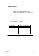
b. Message write display Message write method can be selected. - Separate/Common message display on trend display 1. Common: Messages write on all trend display groups 2. Separate: Message write on a trend screen or some trend screen Message Write with Internal Switch Messages can be written with internal switch. - Specifying message number can be set in INT-SW1 (SW001-SW008), INT-SW2 (SW013-SW020), and INT-SW3 (SW025-SW030) - Message write can be set in DI/RI/SW. Table 1.2.
1.2. Computation Function Expansion Computation functions are expanded in measurement and control computation. Measurement computation expansion The followings can be used in measurement computation equation. - Additional data: CI01- CI10, DI/DO/SW data, W01-W36 - Additional operand: CLOG.MAX(), CLOG.MIN(),CLOG.AVE(). CLOG.P-P(), [eq1?eq2: eq3] Up to 120 characters can be used in measurement computation equation.
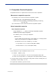
1.3 Modbus Master Communication Setting Expansion The followings are added to “Read cycle” and “Time out” in Modbus Master setting.
1.4 Green Series Communication Function Expansion Additional Connecting Mode (Controllers) The external controllers kinds, of which parameters CX can auto-read are added as follows. (The functions that CX supports UT series can be used.) - Additional connecting kinds: US1000, UT100 series (UT130, UT150, UT152, and UT155) The following control modes and alarm kinds can be selected from CX.
2.Communication Command The following commands related to messages, contact input, internal switch, and logic computation are added (The contents that is different from standard specification are described) a)SG: Message character strings setting Syntax SG p1, p2, p3 p1: Message group No. (1-30) p2: Message No. (1-8) p3: Message (16 alphanumeric characters) b) MS: Message Write Syntax MS p1, p2 p1: Message group No. (1-30) p2: Message No.
g) XU: Sets the channel identification display, memory alarm time, language, whether or not to use the partial expanded display function and the batch function Syntax XU p1, p2, p3, p4, p5, p6 p5: batch function use or not (USE, NOT) p6: specify message display mode (COMMON, SEPARATE) h) SO: Sets the computing equation Syntax SO p1, p2, p3, p4, p5, p6, p7 p3 computing equation (Max 120 characters) - CI01-CI10, W01-W36, DO/DI/SW data, CLOG.MAX(), CLOG.MIN(),CLOG.AVE(). CLOG.
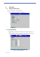
3. Procedure 3.1 Message Mode Setting “MENU” key (Control mode)> setup mode>#9 AUX - Select message mode from “Common” or “Separate” Figure 3.1 Message mode setting 3.2 Message Setting Press the “MENU” key (Control mode) > “MENU” key (Set mode) > #7 “Message” soft key. - Select the group No. of the message you want to set, and then specify the desired group name and enter message contents (up to 16 characters). Fig. 3.
3.3 Writing Messages on Trend Display Screen 1. Press “FUNC” key and press soft key corresponding to “Message”. 2. A list of message group Nos. and group names will appear. Fig. 3.3-1 Writing messages -1 3. Select the group No. of the message you want to write. Click the soft key corresponding to the message you want to write. The message will be written. Fig. 3.3-2 Writing messages -2 Note In case of “separate” for message mode, messages on trend display are written as follows.
3.4 Specify Message Number and Message Write with Internal Switch Press the soft keys in the following sequence: Press the “MENU” key (Control mode) > “FUNC” key for a few seconds (Setup Mode) > #10 “Control” soft key > #2 “DI/DO/SW-registration, AUX (Alarm mode…)” soft key. 1. Select a soft key corresponding to “INT-SW1” or “INT-SW2”or “INT-SW3”. 2. Define Message number you wish to use. 3. 1-240 messages can be selected Figure 3.
3.5 Logic Computation Equation Example with SELECT Operator This section explains an example of SELECT operator in logic computation. The combination use of If-Then-Else ([eq1?eq2: eq3]) and program control operator (.SELECT()) enable to check action error. 1. Assign “ProgramRun”, ProgramReset”, “HOLD”, “Advance” to internal switch number you want to set. Figure 3.5-1 Internal switch setting 2. Set/input logic computation equation with SELECT operator.
Control constant change on tuning screen Control constants (loop and pattern number) which are used within SELECT operator can be changed by assigning them on the tuning screen. - The control constants are registered at control (tuning setting) of setup mode. The constants are changed on tuning screen. (See below figure) Figure 3.5-2 Tuning setting Figure 3.
4. DAQSTANDARD Following functions are expanded in standard DAQSTANDARD. - Message function - Computation function (measurement and logic computation) 4.1 Viewer Group number and message number are described as three-digits number. The first digit from the left and second digit in the center means group number. The last digit in the right means message number. (Example) message group number 10, message number 3 Æ 103 4.2 Hardware Setting(Config) 4.2.
4.2.2 Message Write with Internal Switch Make the basic settings of message write function with internal switch. Click the [Setup] tab then select the [DI/DO/SW-Regist] settings from the list that appears on the left of the screen. Or, you can select the items by choosing [Control Settings] [Setup Mode]-[DI/DO/SW-Regist]. Figure 4.2.2 internal switch setting In internal switch(INT-SW1 to INT-SW3), set message.
4.2.3 Expanded Computation Function Control computation expansion: Logic computation - 4 rules arithmetic (+,−,*,/) and operators (.Select () can be used in logic computation. Figure 4.2.3 Logic computation Measurement computation expansion - The followings can be used in measurement computation function. Additional data: CI01-CI10, DI/DO/SW data, W01-W36 Additional operator: CLOG.MAX(), CLOG.MIN(),CLOG.AVE(). CLOG.