Instruction Manual DR130/DR231/DR241 Hybrid Recorder (Stand-alone model) IM DR231-01E IM DR231-01E 9th Edition
Foreword Thank you for purchasing the YOKOGAWA Hybrid Recorder DR130, DR231 or DR241. This User's Manual contains useful information regarding the instrument's functions and operating procedures, as well as precautions that should be observed during use. To ensure proper use of the instrument, please read this manual thoroughly before operating the instrument. Keep the manual in a safe place for quick reference whenever a question arises.
Unsupported Functions As Classified by the Style Number The following functions are not available for style number S1 • Computation function (including remote RJC) • Saving and reading of measured data, computated data and set-up data (FDD function) • Summer/Winter time • RS-422-A/RS-485 communication module • Report function • Ethernet module • Measurement of active power and apparent power on ch3 to ch6 for power monitor modules • Flag (for /M1 option) • Group reset (for /M1 option) The following function
Checking the Contents of the Package Unpack the box and check the contents before operating the instrument. In case the wrong instrument or accessories have been delivered, or if some accessories are not present, or if they seem abnormal, contact the dealer from which you purchased them. Futhermore, please contact a Yokogawa representative to order any of parts as follows. Main Unit DR130/DR231/DR241 Check that the model and suffix code given on the name plate are according to your order.
Checking the Contents of the Package Modules Check that the model code given on the name plate is according to your order. Note that the input modules at the DR130/DR231/DR241 are fixed and cannot be moved.
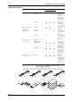
Checking the Contents of the Package Standard Accessories Name Part No. Q'ty 1. Power cord 2. Fuse see page 3 A1350EF 1 1 A1354EF 1 A1105JC 1 B9627AZ B9627AY B9855AY Presence/Absence DR130 3. DC power terminal connector 4. Ribbon cassette 5. Chart paper 6. Mounting brackets 7. User's Manual DR231 DR241 ✓ ✓ ✓ ✓ 1 1 ✓ ✓ ✓ ✓ ✓ 1 ✓ ✓ ✓ ✓ B9900CW 1×2 IMDR231-01E 1 IMDR231-11E 1 ✓ IMDP12013-61E 8. Data acquisition software DAQ 32 DP120-13 Description 1 Timelag 2.
Checking the Contents of the Package Optional Accessories Name Shunt resistance Shunt resistance Shunt resistance Shunt resistance Shunt resistance Shunt resistance Model DV300-011 DV300-012 DV300-101 DV300-102 DV300-251 DV300-252 Description 10Ω, for screw 10Ω, for clamp 100Ω, for screw 100Ω, for clamp 250Ω, for screw 250Ω, for clamp Rack mount kit Rack mount kit DV400-013 DV400-015 for DR231 for DR130 Name DAQ 32 DAQ 32 Plus Model DP120-13 DP320-13 Description Windows 95/98 and Windows NT Windows
Safety Precautions This instrument is an IEC safety class I instrument (provided with terminal for protective grounding). The following general safety precautions must be observed during all phases of operation, service and repair of this instrument. If this instrument is used in a manner not sepecified in this manual, the protection provided by this instrument may be impaired. Also, YOKOGAWA Electric Corporation assumes no liability for the customer’s failure to comply with these requirements.
How to Use this Manual This User's Manual consists of the following fourteen chapters. 8 Chapter Chapter 1 Title System Configuration Description Explains the position of the DR within DARWIN, its configuration, etc.. Chapter 2 Functions Explains the functions of the DR. Operating procedures are not explained here.
Conventions Used in this Manual Used Symbols The following symbol marks are used to attract the operator's attention. Affixed to the DR130/231/241, indicating that for safety, the operator should refer to the appropriate User's Manual. For a list of the User's Manuals, refer to page 1. Describes precautions that should be observed to prevent the danger of injury or death to the user. Describes precautions that should be observed to prevent damage to the DR130/231/241.
10 IM DR231-01E
Contents Foreword .................................................................................................................................................................................. 1 Checking the Contents of the Package ..................................................................................................................... 3 Safety Precautions .........................................................................................................................................
Contents Chapter 6 Chapter 7 Setting the Recording Conditions 6.1 6.2 Setting the Recording Mode/Engineering Unit/Recording Channel and Recording Interval .............. 6-1 Setting the Chart Speed ........................................................................................................................ 6-4 6.3 6.4 6.5 6.6 Setting Recording Zones and Partially Expanded Recording ..............................................................
Contents Chapter 12 Executing Compuration (Available with the /M1 Model) 12.1 12.2 Overview of the Computation Function ............................................................................................. 12-1 Setting a Computation Equation ......................................................................................................... 12-4 12.3 12.4 12.5 Setting a Constant .................................................................................................................
List of Menus and Set-up Data The following is a list of set-up data, procedures to switch to different setting modes, and setting menu.
List of Menus and Set-up Data Computation Settings Parameters Computation equation Constant Perform computation Clear measured data and perform computation Stop computation Clear incomplete measurement status Handling of computation error/time axis setting of TLOG SUM Procedure SET key* SET key* FUNC key** FUNC key** Selecting menu SET=MATH SET=CONST MATH START MATH CLR START Reference Section 12.2 Section 12.3 Section 12.4 Section 12.4 FUNC key** FUNC key** MATH STOP MATH ACK Section 12.
1.1 About DARWIN What is DARWIN? Personal computer D CH=001 RANGE=TC TYPE-T Hybrid Recorder 001 002 003 004 005 006 007 008 009 010 DA100 DR130 DR230 011 012 013 014 015 016 017 018 019 020 021 022 023 024 025 026 027 028 029 030 DR240 Subunit FD Input/output modules Extension cables (max.
1.2 Names of Parts DR130 Portable hybrid recorder Front Main display (See chapter 4.) Sub-display 1 (See chapter 4.) Sub-display 2 (See chapter 4.) Status indicator Operation panel (See chapters 3 to 12.) Handle to open/close the front door Front door Floppy disk drive (Only for DR130-1) Power switch (See page 3-18.) Rear (Example of DR130 with 20 input channels) AC power supply model Heat sink fins Power connector ( See page 3-21.) Power fuse ( See page 13-2.
1.2 Names of Parts DR231 Desk-top hybrid recorder Front Main display (See chapter 4.) Sub-display 1 (See chapter 4.) Sub-display 2 (See chapter 4.) Status indicator 1 System Configuration Operation panel (See chapters 3 to 12.) Handle to open/close the front door Front door Power switch (See page 3-18.) Floppy disk drive (Only for DR231-1) Rear (Example of DR231 with 30 input channels) AC power supply model Heat sink fins Power fuse ( See page 13-2.) Power connector ( See page 3-21.
1.2 Names of Parts DR241 Panel-mount hybrid recorder (component type) Front Main display (See chapter 4.) Sub-display 1 (See chapter 4.) Sub-display 2 (See chapter 4.) Status indicator Operation panel (Located behind the front door. See chapters 3 to 12.) Handle to open/close the front door Front door Floppy disk drive (Only for DR241-1) Power switch (Located inside the front door. See page 3-18.) Rear (Example of DR241 with 30 input channels) Heat sink fins Power fuse (Located inside the instrument.
1.2 Names of Parts DR231 Desk-top hybrid recorder Front Main display (See chapter 4.) Sub-display 1 (See chapter 4.) Sub-display 2 (See chapter 4.) Status indicator 1 System Configuration Operation panel (See chapters 3 to 12.) Handle to open/close the front door Front door Power switch (See page 3-18.) Floppy disk drive (Only for DR231-1) Rear (Example of DR231 with 30 input channels) AC power supply model Heat sink fins Power fuse ( See page 13-2.) Power connector ( See page 3-21.
2.1 Display Functions The inter-active front panel display consists of three rows. The first row is the main display, and the second and third row are sub-display 1 and 2 respectively. Monitor Mode and Status Display Status Display Indicators at the right side of the display will light up to show that recording is in progress (refer to page 2-5), alarms are occuring (refer to page 2-14), keys are locked (refer to page 2-18) and chart needs to be replaced (refer to page 2-19).
2.1 Display Functions Display for Setting the Type of Input, Computation and Recording Conditions Menus for setting each of the following functions will be displayed.
2.2 Measurement Input Functions Input Type DC Voltage Measurements can be done after selecting the measurement range per channel. The minimum range is 20mV, the maximum range is 50V. Resistance Temperature Detector Measurements can be done after selecting the type of resistance temperature detector (RTD) per channel.
2.2 Measurement Input Functions Scan Interval • The duration of time (one scan) in which the measurement of all channels is carried out, is called the scan interval. • This interval can be set to any value from 2 to 60s, and this range is the same for the 10ch, 20ch and 30ch model. A/D Integration Time This instrument measures the input signal after putting it through an A/D converter. In order to minimize the noise imposed on the input signal, specific integration times exist.
2.3 Recording Functions Chart Speed The speed at which the chart moves when performing trend recording can be selected from any value between 1 to 1500mm/h. Two types of chart speeds can be set. When you are not using the Event/Action function, which will be described later on in this manual, chart speed 1 will be valid. When the Event/Action function is being used, you can select whether chart speed 1 will change to speed 2 according to the event status.
2-6 Starting date/time of Digital printout Digital printout (Page 2-5) Left margin Chart speed (Page 2-5) Channel No. or tag of manual printout Manual Printout (Page 2-13) Starting date/time of manual printout Scale value (Page 2-10) Reference point of xcale (Page 2-8) Header (Page 2-13) Trend recording (Page 2-5) Ending time of previous dot recording (Page 2-8) Title (Page 2-13) Starting time of dot recording (Page 2-8) Message (Page 2-13) Channel No.
IM DR231-01E 2-7 Starting date/time of Digital printout Chart speed (Page 2-5) Digital printout (Page 2-5) Left margin Header (Page 2-13) Channel No.
2.3 Recording Functions Recording Format You can modify the recording format of measurement values according to your own preferences. The following selections are available. Items common for Analog Trend and Logging mode Printing Channel No. or Tag When printing measurement values, the corresponding channel number or a preset tag can be recorded with it. This selection will also affect the display the same way. The number of characters of a tag which will be printed out, can be selected too.
2.3 Recording Functions Recording Colors The color of trend recordings can be selected per channel. The colors which can be selected are black, purple, red-purple, navy blue, red, blue, brown, green, orange and yellowish green. The recording color of the numerical values in the logging mode is purple only. Recording Interval Recording interval = Scan interval × N where N is an integer satisfying N ≤ 720 / (scan interval × chart speed). 720 is fixed.
2.3 Recording Functions Recording Span The maximum value and the minimum value of the measurement range are decided when setting the type of input. The difference between the minimum value and maximum value which will be recorded within this measurement range, is called the recording span. The value on the left and right side of the recording are called the left span and right span respectively.
2.3 Recording Functions Partially Expanded Recording When carrying out trend recording, partially expanded recording enables you to compress a part of the recording span in order to examine the expanded (other) part of the span in more detail. The left boundary of the recording span being 0%, and the right boundary of the recording span being 100%, a segment of the recording span can be compressed. The following example shows a situation where 25% of the recording span has been compressed.
2.3 Recording Functions List Printout A list printout will show the following items.
2.3 Recording Functions Manual Printout One scan of measurement values of selected channels will be recorded as digital values together with the date and time. This printout can be executed by key operation or by event/action function (refer to page 2-18). Refer to page 2-6, 2-7 for a recording example. Header Printout For the header, you can print as many as 60 characters each on 5 lines (DR130) or as many as 80 characters each on 5 lines (DR231/241) and its recording can be executed by key operation.
2.4 Alarm Function This function will show an alarm on the display or generate an alarm output signal with /A4 or /R1 option when the measurement conditions of a channel exceed/fall below preset values. Up to four alarms can be set for each channel. Type of Alarms Six types of alarms are available, namely high limit alarm, low limit alarm, high limit on rate-ofchange, low limit on rate-of-change, difference high limit and difference low limit.
2.4 Alarm Function Operation Mode Energizing/De-energizing Setting The alarm output relays can be selected to be energized or de-energized on alarm occurrence. Using de-energizing, the alarm output relay will be activated when the power drops in the same way as when an alarm occurs. This setting can be done for each relay individually.
2.4 Alarm Function Recording Alarm Information Analog Trend Mode When an alarm occurs (or releases), the occurrence/release mark, message, channel No. or tag and time of occurrence/release will be printed on the right side of the chart. Logging Mode • If an alarm occurs, the type of alarm will be printed together with the measured value. • If an alarm occurs (or is canceled), the alarm occurrence/cancellation mark, channel No.
2.5 Standard Computation Functions Standard computations such as difference between channels and linear scaling can be set with measurement input settings. A moving average computation is also available. Difference between Channels Linear Scaling This function changes the left and right span of the recording span to left and right scale values which are converted to a different physical quantity. This can be applied to each channel and a different engineering unit can be entered for display and printouts.
2.6 Other Functions Event/Action Function Following the occurrence of an event such as remote control signal (12), alarm, internal switch, chart end signal, timer, match time or key operation, any of the following actions can occur.
2.6 Other Functions External Input/Output Function (Option) Alarm Output When /A4 option is installed ten external output relays (make contact) can be used, whereas with /R1 option is installed, two external output relays (transfer contact) can be used. These relays will be operated when an alarm occurs. For details concerning their settings and their relation with alarms, refer to page 2-15, 2-16.
2.6 Other Functions Carrying Handle (Option) A carrying handle is available as an option for the stand-alone model DR231 for making transport of the instrument easier. FDD (DR130-1, DR231-1, DR241-1) This function enables saving/reading of measured data, computed data and set-up data for SET mode to/from the internal RAM disk, and saving/reading of set-up data for SET and SETUP modes to/from a floppy disk.
3.1 General Precautions for Installation Safety Precautions Read the safety precautions Make sure to read the safety precautions described on page 4 before using the instrument for the first time. Do not remove any covers from the instrument For internal inspection or adjustment, contact your nearest sales representative. Addresses may be found on the back cover of this manual. Power cable Nothing should be placed on the power cable; it should also be kept away from any heat sources.
3.2 How to Install Installation Conditions The instrument must be installed in a location where the following conditions are met. Ambient temperature and humidity • Ambient temperature: 0 to 50°C (5˚ to 45˚C, when the recorder includes a floppy disk drive) • Ambient humidity: 20 to 80%RH for 0 to 40°C, 10 to 50%RH for 40 to 50°C However, no condensation should be present.
3.2 How to Install DR130 AC power supply model 30 207 98.8 221 6 338 25 3 252 Installation and Wiring DC power supply model 30 98.8 Rack Mounting Dimensions AC power supply model Panel face 32 482.6±1 11.3 310 146.1 44.5 44.5 146.1 44.5 1 2 1 37.5 1&2 : Removed 44.5 37.5 310 44.5 7 7 11.
3.2 How to Install DR231 AC power supply model 438 207 98.8 25 266 30 DC power supply model 252 30 98.8 Rack Mounting Dimensions AC power supply model Panel face 482.6±1 30 265.9±1 190.5±0.5 37.7 6.8 190.5±0.5 265.9±1 11.3 37.7 6.8 11.
3.2 How to Install 444 203 280 100 288 40 Panel cutting dimension 281 At least 80 mm At least 520 mm +2 425 0 IM DR231-01E 3-5 3 Installation and Wiring DR241 • Panel mounting Use steel plates 3 mm thick or more for panel mounting. The external and panel cutting dimensions for the DR241 are shown below. The panel cutting dimensions include the cutting interval for multiple mounting on the same panel.
3.3 Installing the Chart and Ribbon Cassette Installing the Chart Preparing the Chart 1. To prevent double feed of the folded chart, sufficiently ruffle and fan the chart on both folded side ends. Note • Use chart papers specified by Yokogawa (part number: B9855AY for DR130, B9627RY or B9627AY for DR231/DR241). Using chart papers other than those specified may cause problems such as large recording errors or the paper getting caught under the sprocket. Preparing the Chart Cassette 2.
3.3 Installing the Chart and Ribbon Cassette Loading the Chart Paper 5. Place the chart paper in the chart storage housing, and move the paper to the left. Position the chart so that its round perforations are on the left and the recording surface faces upward when the chart paper is wound around the platen. Chart paper Platen Chart pressure plate 2 Chart storage housing 3 Chart paper Fold line of chart paper Sprocket Right and left position mark Chart rest cover Guide pin Chart pressure plate 1 7.
3.3 Installing the Chart and Ribbon Cassette Loading the Ribbon Cassette Preliminary Preparation · If the carriage to which the ribbon cassette is to be mounted is located near the right end, turn off the power and bring the carriage to a location near the left end by turning the screw shaft, then load the ribbon cassette.
3.3 Installing the Chart and Ribbon Cassette 7. Push the ribbon cassette to the left until the latch engages. Check that the three white lines of the printer head are not visible when viewed from the front. If the white lines can be seen, the ribbon cassette is not properly loaded. Push the cassette to the left again. Note • Check that the ribbon cassette is properly loaded in the carriage.
3.3 Installing the Chart and Ribbon Cassette 5. Push the ribbon cassette to the left until the latch engages. Check that the three white lines of the printer head are not visible when viewed from the front. If the white lines can be seen, the ribbon cassette is not properly loaded. Push the cassette to the left again. 6. Turn the ribbon cassette rotating knob once more in the direction of the arrow (counterclockwise) to take up the ribbon slack. 7.
3.4 Connecting the Interface Cables When connecting a personal computer to the instrument via a communication interface, observe the following: GP-IB The GP-IB connector of the GP-IB communication module is a 24-pin connector of IEEE St'd 488-1978. Only use cables that conform to IEEE St'd 488-1978 as a communication cable. Connection Procedure Connect the cable as shown in the figure below.
3.4 Connecting the Interface Cables RS-232-C Communication Settings Communication parameters are set using the three switches located on the RS-232-C modules. Switch 1 1 2 3 4 ON OFF Data length Baud rate Switch 2 1 2 3 4 ON OFF Not used Stop bit Parity Switch 3 1 2 3 4 ON OFF Not used Handshake format Switch 1 and No.4 of switch 2 Baudrate 150 300 600 1200 2400 4800 9600 19200 38400 Data length 7 bits 8 bits dipswitch No.1 OFF OFF OFF OFF ON ON ON ON OFF No.2 No.3 No.
3.4 Connecting the Interface Cables Connecting the RS-232-C Cable For details on connecting the RS-232-C connector of the RS-232-C communication interface module to a personal computer, see IM DR231-11E, "DR231/DR232/DR241/DR242 Communication Interface User's Manual." CAUTION When (dis)connecting the RS-232-C cable, turn OFF the power of both the personal computer and the instrument. If the power is not turned OFF, malfunctions may occur and the internal circuitry may be damaged.
3.4 Connecting the Interface Cables Parity (No.1 to 2 of SW2) Parity No.1 No.2 None ODD EVEN OFF OFF ON OFF ON OFF ←Default Setting Stop bit (No.3 of SW2) Stop bit No.3 1 2 OFF ON ←Default Setting Switch between four-wire/two-wire systems (No.4 of SW2) four-wire/two-wire No.4 four-wire two-wire OFF ON ←Default Setting Minimum response time (No.1 to 3 of SW3) Minimum response time No.1 No.2 No.
3.4 Connecting the Interface Cables For details on connectin the RS-422-A/RS-485 connector of the RS-422-A/RS-485 communication interface module to a personal computer, see IM DR231-11E, “DR231/DR232/ DR241/DR242 Communication Interface User’s Manual.” CAUTION When (dis) connecting the RS-422-A/RS-485 cable, turn OFF the power of both the personal computer and the instrument. If the power is not turned OFF, malfunctions may occur and the internal circuitry may be damaged.
3.5 Connecting the Signal Lines W WARNING • To prevent electric shock always make sure that the power supply is turned OFF before connecting. • When 30VAC or 60VDC and more is applied to the output terminal of the alarm module or the output terminal of the DI/DO module, use double-insulated wires(withstand voltage performance: more than 2300VAC) for those wires which apply 30VAC or 60VDC and more. All other wires can be basic-insulated(withstand voltage performance: more than 1350VAC).
3.5 Connecting the Signal Lines Note Make sure that the equipment connected to the signal in-/output conforms IEC (CSA) 950 or IEC (CSA) 1010. Also, make sure to use cables that conform to IEC (CSA) standards. In case you are using an internal RJC in case of thermocouple input, the following considerations are necessary to stabilize the temperature at the terminals. Always make sure to re-apply the terminal cover; The thermal capacity of the wiring should be small (cross sectional area of less than 0.
3.
3.5 Connecting the Signal Lines Diagram of Terminal Block Three-phase Model Single-phase Model Wire clip Wire clip V1 V1 I1 I1 V2 I2 V3 3 I3 Installation and Wiring 9mm Wire clip • Strip 9 mm of insulation off the leadwire. • ALWAYS clamp the leadwire with the wire clip. • The recommended torque for fastening the wire clip screw is 0.4 to 0.5 N•m.
3.
3.6 Connecting the Power Cable and Turning the Power ON/OFF DR130/DR231 (when using the accessory power cable) Follow the warnings below to avoid electric shock or damaging the instrument. WARNING • Connect the power cable only after confirming that the voltage of the power supply matches the rated electric power voltage for this instrument. • Connect the power cable after checking that the power switch of this instrument is turned off.
3.6 Connecting the Power Cable and Turning the Power ON/OFF DR241 (when connecting wires to screw terminals) Follow the warnings below to avoid electric shock or damaging the instrument. WARNING • Connect the power wires after checking that the power supply is turned off to prevent electric shock. • To prevent fire, use 600 V PVC insulated wire (AWG18) for both power and ground wiring (cross section of 0.83 mm2 or thicker, anti-galvanic corrosion finish, insulation thickness more than 0.
3.6 Connecting the Power Cable and Turning the Power ON/OFF • Connecting procedure for DC power supply 1. Check that the power switch is turned off. 2. Remove the cover protecting the power terminals. 3. Connect the power supply wires and the function ground wire to the power terminals. 4. Replace the cover. Rated supply voltage: 12 to 28 V DC, operating supply voltage: 10 to 32 V DC Power consumption: About 80 VA max.
3.6 Connecting the Power Cable and Turning the Power ON/OFF Turning Power ON/OFF The power switch is a push-button; the power is turned on when pressed once and turned off when pressed again. DR130 DR231/DR241 Power switch Power switch Note • Before turning the power on, check that each unit is properly mounted and the power cable is correctly connected.
3.7 Setting the Date and Time DISP SET=CLOCK ALARM >Select Setting Parameter CHART CLOCK MODE RECORD ESC RECORD FUNC PRINT INS DEL FEED CHART RANGE ALARM M. F U N C 1 KEYLOCK CHART SET ENTER M. F U N C 2 (Main menu) SET= (Lower menu) CLOCK 96/01/01 03:36:23 ENTER ENTER >Set Date & Time YY/MM/DD HH:MM:SS *** SET OK*** ESC Setting the Date and Time Set them in the order of year/month/day, hour:minutes:seconds. • Year: Specify the lower two digits of the year.
3.8 Countering Noise Types and Features of Noise Sources Commercial Power Supply It is necessary to consider both 50 and 60Hz as noise components. It is important to note that a power supply line in which a thyristor or inverter is incorporated functions not only as an “energy surplus line”, but also as a “supply surplus line”. Thyristor (SCR) A thyristor is used to control power through ON/OFF modulation of commercial power by controlling the phase angle.
3.8 Countering Noise Voltage waveform 3 Installation and Wiring Current waveform Voltage/current waveforms of an inverter Relay A relay is frequently used to amplify alarm and temperature controller outputs. However, since a counter-electromotive force (counter e.m.f.) is produced by coil inductance when the relay is turned off and the e.m.f. becomes noise, care must be taken. Due to chattering at the relay contact, tens to hundreds of kHz noise occurs mainly in bursts.
3.8 Countering Noise Example of a high-frequency induction furnace * Due to electromagnetic induction, current i flows through the conductor, creating joule heat which heats the furnace. J=i2r Furnace C Φ Inverter power supply (20 to 3500kW) Power supply r i (0.
3.8 Countering Noise In the figure on the previous page, due to common mode voltage ECM, noise currents i1 and i2 flow through the impedance to grounds Z1 and Z2 and coupling impedance Z3, resulting in the generation of normal mode noise ENM between input terminals H and L. Like this, common mode noise is converted to normal mode noise. The amp is equipped with a built-in filter and in case of output EO the normal mode noise will be eliminated.
3.8 Countering Noise Balance each other Input voltage (instantaneous value) DC voltage (average value) integration time Normally, an integration time of 20ms (50Hz) or 16.7ms (60Hz) is selected depending on the commercial power supply frequencies. A 100-ms integration mode is added to the instrument to achieve superior noise rejection. However, when using the 100ms setting, the smallest measurement interval is longer than in case of the 20ms or 16.7ms setting.
3.8 Countering Noise • for input lines: an increase of impedance; Always separate the input line from the noise source lines (power and alarm lines). Step 1 : Install a separator. Separator Signal* lines Power lines Special class 3 ground (10Ω or less) Signal lines* Power lines at least 15 cm Step 3 : Leave a clearance of at least 15 cm between the signal lines and power lines.
3.8 Countering Noise Step 2 : Change the position of the noise source. A) Leakage magnetic flux of transformer: Φ = strong Φ = weak Move the instrument to a location where the influence from magnetic flux is weak. B) Sparks spark strong electromagnetic radiation weak electrogmagnetic radiation Move the instrument to a location where the influence from electromagnetic radiation is weak. • Grounding: a decrease of impedance The grounding method is the point of common mode noise suppression.
3.8 Countering Noise • Shielded and twisted pair (prevention of electromagnetic coupling): an increase of impedance If it is difficult to keep the noise source away from the measuring instrument due to space limitations, the use of a shielded twisted pair is effective. • electrostatic coupling can be completely cut off by shielding; • for a magnetic field, shielding with a magnetic material (iron, permalloy, etc.) can be employed.
3.8 Countering Noise • Insertion of noise filter and noise killer If the influence from noise cannot be eliminated by the methods described before, use noise filter or noise killer. Power line noise rejection Step 1 : Insert an isolation transformer into the power line.
3.8 Countering Noise • Relay noise suppression • To prevent noise and protect the contact, connect the diode to the relay coil terminal directly. Dc external • In addition to the above measure, reduce power supply the rated voltage of the relay circuit as much as possible for higher reliability. • It is necessary to choose a diode that R matches the relay. Generally, a diode whose rated rectifying current is at least three times the current flowing through the relay coil must be used.
4.1 Using the AUTO Mode DISP MODE RECORD ESC FUNC PRINT INS DEL FEED RANGE ALARM CHART SET M. F U N C 1 ENTER M. F U N C 2 AUTO Mode for the Main Display 1 Select the main display using the DISP key. Direct the arrow mark on the Sub-display upward. 2 Select “AUT” using the MODE key. Sub-display 1 003 0.0045V 004 0.0931V 4 AUT Sub-display 1 004 0.0926V 005 0.0824V AUT AUTO Mode for Sub-display 2 1 Select sub-display 2 using the DISP key.
4.1 Using the Auto mode AUTO Mode for the Main Display • Channel No. The first seven characters are used. The first three characters are used to display the channel number. The first character always displays “0”. “A” will be displayed in the case of optional computation channels. If you selected TAG at the channel No./TAG setting in the set-up mode (refer to 10.2 on page 10-4), the assigned tag will appear for each channel.
4.1 Using the Auto mode AUTO Mode for Sub-display 1 Data of two channels are displayed here simultaneously. • Channel No., Difference between Channels (delta), Alarms, Measurement Values Same as for the main display. • Engineering Units If the channel number has been selected to appear on the display, the first four characters of the unit setting are used for displaying engineering units.
4.2 Using the MANUAL Display DISP RECORD MODE ESC FUNC PRINT INS DEL FEED RANGE ALARM CHART SET M. F U N C 1 ENTER M. F U N C 2 MANUAL Display for the Main Display 1 Select the main display using the DISP key. 2 Select “MAN” using the MODE key. Sub-display 1 002 0.0034V 003 MAN 0.0920V 3 Select the required channel using the keys. Main display 001 0.0057 V MANUAL Display for Sub-display 1 1 Select sub-display 1 using the DISP key. 2 Select “MAN” using the MODE key.
4.2 Using the MANUAL Display MANUAL Display for the Main Display • Channel No., Difference between Channels (delta) and Alarms Same as for the AUTO mode (refer to page 4-2). • Measurement Values Same as for the AUTO mode (refer to page 4-2), except for the following. When the input type of the channel is set to “SKIP”, then “SKIP” will be displayed. When the channel other than the channel of the input module is selected, “- - - - - -” appears.
4.3 Using the PAGE Display DISP RECORD MODE ESC FUNC PRINT INS DEL FEED RANGE ALARM CHART SET M. F U N C 1 ENTER M. F U N C 2 1 Select the main display using the DISP key. 2 Select “PGE” using the MODE key. Sub-display 1 002 0.1936V 003 0.0995V 3 Select the required set of five channels (page) using the PGE keys. Display 0.0173V 006 007 009 0.0197V 0.0162V 008 010 0.0074V 0.
4.4 Using the ALARM SEARCH Display DISP RECORD MODE ESC FUNC PRINT INS DEL FEED RANGE ALARM CHART SET M. F U N C 1 ENTER M. F U N C 2 ALARM SEARCH Display for the Main Display 1 Select the main display using the DISP key. 2 Select “SER” using the MODE key. Sub-display 1 003 0.0054V 004 0.0319V 4 SER Setting the Monitor Mode Display ALARM SEARCH Display for Sub-display 1 1 Select sub-display 1 using the DISP key. 2 Select “SER” using the MODE key. Sub-display 1 004 H 0.
4.4 Using the ALARM SEARCH Display Points to Note when Using the ALARM SEARCH Display • When all three displays are set to ALARM SEARCH display, the main display will start displaying data of the channel with the smallest channel number, on sub-display 1 data of the next two channels will be displayed, while on sub-display 2 data of the next two channels will be displayed. When the data are updated, the display will be replaced with data of the next, consecutive, channel.
4.5 Using the BARGRAPH Display DISP MODE RECORD ESC FUNC PRINT INS DEL FEED RANGE ALARM CHART SET M. F U N C 1 ENTER M. F U N C 2 1 Select the sub-display 1 using the DISP key. 2 Select “BAR” using the MODE key. Display 003 0.0172V 005 < 2.0000 0.0123V 4 BAR Bargraph Display Sub-display 1 can be turned into a bargraph display. The measurement data on the main display are displayed as a bargraph on sub-display 1.
4.6 Using the ALARM STATUS Display DISP MODE RECORD ESC FUNC PRINT INS DEL FEED M. F U N C 1 RANGE ALARM CHART SET ENTER M. F U N C 2 ALARM STATUS Display for Sub-display 1 1 Select the sub-display 1 using the DISP key. 2 Select “ALM” using the MODE key. Sub-display 1 ALM 001 3 Select the range to be displayed in blocks of 10 channels. Sub-display 1 ALM 011 ALARM STATUS Display for Sub-display 2 1 Select the sub-display 2 using the DISP key. 2 Select “ALM” using the MODE key.
4.7 Using the RELAY STATUS Display DISP MODE RECORD ESC FUNC PRINT INS DEL FEED RANGE ALARM CHART SET M. F U N C 1 ENTER M. F U N C 2 RELAY STATUS Display for Sub-display 1 1 Select the sub-display 1 using the DISP key. 2 Select “RLY” using the MODE key. Sub-display 1 S01 4 RLY Setting the Monitor Mode Display 3 Select the range to be displayed in blocks of 10 channels. Sub-display 1 S11 RLY RELAY STATUS Display for Sub-display 2 1 Select the sub-display 2 using the DISP key.
4.7 Using the RELAY STATUS Display Relation between the Relay Status and Internal Switch If the relay status of the internal switches is being displayed, an “S” will be displayed as the first character. The next two characters show the number of the internal switch which corresponds to the first batch of the display and range from 01 to 51. There are 60 internal switches.
4.8 Using the CLOCK (Date & Time) Display DISP MODE RECORD ESC FUNC PRINT INS DEL FEED M. F U N C 1 RANGE ALARM CHART SET ENTER M. F U N C 2 1 Select the sub-display 2 using the DISP key. 2 Select “CLK” using the MODE key. Sub-display 1 and 2 005 0.8210V 006 Dec. 30. 95 13:16:19 0.0095V CLK 4 IM DR231-01E 4-13 Setting the Monitor Mode Display Clock Display The date and time can be displayed on sub-display 2. According to the set time in 3.
5.1 Setting the Type of Input and Recording Span DISP 001-10:VOLT/2V SPAN=–2.0000/ 2.0000V SKIP VOLT TC RTD DI DELTA SCL MODE RECORD ESC RECORD ALARM FUNC PRINT INS DEL FEED CHART RANGE ALARM M. F U N C 1 KEYLOCK CHART SET ENTER M. F U N C 2 • Press the RANGE key to enter the RANGE menu. • Select/set using the keys. • To escape from a lower menu, press the MODE (ESC) key. Its main menu will appear, although new settings/selections will not be kept.
5.1 Setting the Type of Input and Recording Span From the previous page 001-01:DI/LEVL 001-01:DI/LEVL ENTER LEVL CONT SPAN=_ _ _ _ _ _0/_ _ _ _ _ _1 ENTER >Span limit(0~1) ***SET OK*** ESC 002-02:DELTA/REF Ch=01 002-02:DELTA/REF Ch=01 ENTER >Select Channel No. SPAN= -2.0000/_2.0000V ENTER >Span limit(-2.0000~2.0000V) ***SET OK*** ESC 002-02:RRJC/RJC Ch=01 002-02:RRJC/RJC Ch=01 ENTER >Select Channel No. SPAN= 0.0/1760.0˚C ENTER >Span limit(0.0~1760.
5.1 Setting the Type of Input and Recording Span Setting the Recording Span The measurement range is decided according to the type of input. The recording left and right span must lie within the measurement range. However, the recording span is 0 to 1 for the DI input type. The value on the left side of the SPAN menu shows the left span, and the value on the right side of the SPAN menu shows the right span.
5.2 Setting Linear Scaling and the Recording Span DISP 001-10:SCL:VOLT/2V RECORD > SKIP VOLT TC RTD DI DELTA SCL CHART ALARM MODE RECORD ESC FUNC PRINT INS DEL FEED RANGE ALARM M. F U N C 1 KEYLOCK CHART SET ENTER M. F U N C 2 • Press the RANGE key to enter the RANGE menu. • Select/set using the keys. • To escape from a lower menu, press the MODE (ESC) key. Its main menu will appear, although new settings/selections will not be kept.
5.2 Setting Linear Scaling and the Recording Span From the previous page 001-01:SCL:RTD/PT1 001-01:SCL:RTD/PT1 ENTER PT1 PT2 JPT1 JPT2 PT50 NI1 NI2 NI3 CU1 CU2 CU3 CU4 PT1S PT2S JPT1S JPT2S J263B SPAN=–_200.0/_ _600.0˚C ENTER >Span limit(–200.0~600.0˚C) SCL=_ _ _0.00/_100.
5.3 Configuring the Input Range and Recording Span or the Linear Scaling of a Power Monitoring Channel DISP 001-01:AC/1Ph3W RNG=250-5A/ V1 SPAN= - 1250 / ALARM 002:VA1 MODE RECORD ESC RECORD FUNC PRINT INS DEL FEED CHART RANGE ALARM 1250W M. F U N C 1 KEYLOCK CHART SET ENTER M. F U N C 2 • Press the RANGE key to enter the RANGE menu. • Using and , select and/or enter a value for each of the shaded fields shown below.
5.3 Configuring the Input Range and Recording Span or the Linear Scaling of a Power Monitoring Channel IM DR231-01E 5-7 5 Setting the Input Type/Recording Span/Linear Scaling Setting the Channel Number This procedure sets the channel number for which you want to show and record the values of a parameter selected from the effective voltage, effective current, active power, reactive power, apparent power, frequency, power factor and phase angle which were calculated using the measured data.
5.3 Configuring the Input Range and Recording Span or the Linear Scaling of a Power Monitoring Channel Single-phase two-wire configuration CH1 P1 CH2 VA1 CH3 V1 CH4 I1 CH5 PF1 Var1 FREQ CH6 PH1 PF1 V1 Select from these combinations.
5.3 Configuring the Input Range and Recording Span or the Linear Scaling of a Power Monitoring Channel Setting the Recording Span (SPAN) Set the left and right spans within the limits of an input range. In the SPAN menu item, the lefthand value is the left span and the right-hand value the right span. Set the recording span within the measuring range. The measurable limits vary depending on the measuring range you select, as shown below. 25V-0.5A 25V-5A 250V-0.
6.1 Setting the Recording Mode/Engineering Unit/ Recording Channel and Recording Interval DISP MODE RECORD ESC SET=SYSTEM RECORD ALARM >Select Setting Parameter SYSTEM UNIT TREND TIMER LOGIC COPY FUNC PRINT INS DEL FEED CHART RANGE ALARM M. F U N C 1 KEYLOCK CHART SET ENTER M. F U N C 2 • Press the SET key to enter the SET menu. • Select/set using the keys. • To escape from a lower menu, press the MODE (ESC) key.
6.1 Setting the Recording Mode/Engineering Unit/Recording Channel and Recording Interval From the previous page TIMER ENTER TIMER No.=1 ENTER 1 2 3 4 5 6 1:TIMER MODE=RELATIVE ENTER 1:TIME=00 01: 00 ENTER >Set DD HH:MM:00 ***SET OK*** ESC 1:TIMER MODE=ABSOLUTE ENTER 1:TIME=1h ENTER 1min 2min 3min 4min 5min 6min 10min 12min 15min 20min 30min 1h 2h 3h 4h 6h 8h 12h 24h 1:REF TIME=00:00 ENTER ***SET OK*** ESC Recording Mode (SYSTEM) The following types of recording mode can be selected.
6.1 Setting the Recording Mode/Engineering Unit/Recording Channel and Recording Interval Setting the Recording Interval (TIMER) of the Digital Printout for the Logging and Analog Trend Mode • TIMER No. You can set up to six recording intervals. A recording interval can be set for each channel individually. Refer to 6.4 on page 6-9 for details. • TIME MODE The following two modes can be selected. The default is RELATIVE.
6.2 Setting the Chart Speed DISP SET=CHART ALARM >Select Setting Parameter CHART CLOCK MODE RECORD ESC RECORD FUNC PRINT INS DEL FEED CHART RANGE ALARM M. F U N C 1 KEYLOCK CHART SET ENTER M. F U N C 2 Setting Chart Speed 1 • Press the CHART key to enter the SET menu. • Select/set using the keys. • To escape from a lower menu, press the MODE (ESC) key. Its main menu will appear, although new settings/selections will not be kept.
6.2 Setting the Chart Speed Chart Speed 1 (CHART) This setting specifies the chart speed of ordinary trend recordings. The setting ranges from 1 to 1500mm/h, in 1 mm steps. The default setting is 100mm/h. • Depending on the chart speed, the items channel number/TAG, digital printout, and alarm/ scale/message may not be included in your printout. See the table below for details. Chart speed Channel No.
6.3 Setting Recording Zones and Partially Expanded Recording DISP SET=ZONE ALARM >Select Setting Parameter CHART2 ZONE PARTIAL TAG DIGITAL_PR MAN↑ MODE RECORD ESC RECORD FUNC PRINT INS DEL FEED CHART RANGE ALARM M. F U N C 1 KEYLOCK CHART SET ENTER M. F U N C 2 • Press the SET key for three seconds to enter the SET3 menu. • Select/set using the keys. • To escape from a lower menu, press the MODE (ESC) key. Its main menu will appear, although new settings/selections will not be kept.
6.3 Setting Recording Zones and Partially Expanded Recording Setting Recording Zones (ZONE) This setting specifies the recording zones for each channel. The set left and right position of the zone correspond to the left and right span set at the SPAN menu (recording span). The left value of the ZONE menu corresponds to the value of the left position of the zone, whereas the right value of the ZONE menu corresponds to the value of the right position of the zone.
6.4 Setting Tag, Digital Printout and Manual Printout DISP SET=TAG ALARM >Select Setting Parameter CHART2 ZONE PARTIAL TAG DIGITAL_PR MAN↑ MODE RECORD ESC RECORD FUNC PRINT INS DEL FEED CHART RANGE ALARM M. F U N C 1 KEYLOCK CHART SET ENTER M. F U N C 2 • Press the SET key for three seconds to enter the SET3 menu. • Select/set using the keys. • To escape from a lower menu, press the MODE (ESC) key. Its main menu will appear, although new settings/selections will not be kept.
6.4 Setting Tag, Digital Printout and Manual Printout Tag Setting A tag of up to 16 characters can be assigned to each channel. If the instrument is equipped with the optional computation function or floppy disk drive, this setting can also be made for computation channels A01 to A30. The characters/numbers for the tag can be selected by cursor from the displayed row on sub-display 1. For details on the number of characters which will be printed, refer to 10.2 on page 10-4.
6.5 Setting the Alarm Printout DISP SET=ALARM_PR >Select Setting Parameter ↓TIAL TAG DIGITAL_PR MANUAL_PR ALARM_PR↑ ALARM MODE RECORD ESC RECORD FUNC PRINT INS DEL FEED CHART RANGE ALARM M. F U N C 1 KEYLOCK CHART SET ENTER M. F U N C 2 • Press the SET key for three seconds to enter the SET3 menu. • Select/set using the keys. • To escape from a lower menu, press the MODE (ESC) key. Its main menu will appear, although new settings/selections will not be kept.
6.5 Setting the Alarm Printout Selecting the Alarm Items Although up to four alarm headings can be set per channel, this setting specifies the number of the heading which will be printed. The default setting is 1. If the instrument is equipped with the optional computation function or floppy disk drive, alarm items can also be set for computation channels A01 to A30. The setting can be selected from 1, 2, 3 or 4. All four headings can be assigned to one single channel.
6.6 Setting Scale Printout, List Printout and List Format DISP SET=SCALE_PR ALARM >Select Setting Parameter ↓DIGITAL_PR MANUAL_PR ALARM_PR SCALE PR↑ MODE RECORD ESC RECORD FUNC PRINT INS DEL FEED CHART RANGE ALARM M. F U N C 1 KEYLOCK CHART SET ENTER M. F U N C 2 • Press the SET key for three seconds to enter the SET3 menu. • Select/set using the keys. • To escape from a lower menu, press the MODE (ESC) key. Its main menu will appear, although new settings/selections will not be kept.
6.6 Setting Scale Printout, List Printout and List Format Scale Printout (SCALE PR) This setting can be assigned to each channel individually. The scaled values will be printed out with trend recordings. This printout will not occur when a zone of 49mm or less is set. The scaled values of the following channels will be printed. For example, when the recording zone of ch. 1 is set to 49mm, and of ch. 2 is 150mm, the scaled values of ch. 2 will be printed at the position of ch. 1. The default setting is ON2.
6.7 Entering Messages, Headers and Title DISP SET=MESSAGE ALARM >Select Setting Parameter ↓ LIST_PR LIST_FMT MESSAGE HEADER TITLE↑ MODE RECORD ESC RECORD FUNC PRINT INS DEL FEED CHART RANGE ALARM M. F U N C 1 KEYLOCK CHART SET ENTER M. F U N C 2 • Press the SET key for three seconds to enter the SET3 menu. • Select/set using the keys. • To escape from a lower menu, press the MODE (ESC) key. Its main menu will appear, although new settings/selections will not be kept.
6.7 Entering Messages, Headers and Title From the previous page HEADER ENTER HEADER LINE No.=1 ENTER 1 2 3 4 5 LINE1=_ _ _ _ _ _ _ _ _ _ _ _ _ _ _ _ ENTER >1=[_ _ _ _ _ _ _ _ _ _ _ _ _ _ _ _ ] ↓%&()+-*/.:- - - 0123456789 ABC- - -KL↑ TITLE ENTER ***SET OK*** ESC TITLE=_ _ _ _ _ _ _ _ _ _ _ _ _ _ _ _ ENTER >=[_ _ _ _ _ _ _ _ _ _ _ _ _ _ _ _ ] ↓%&()+-*/.:- - - 0123456789 ABC- - -KL↑ ***SET OK*** ESC Entering a Header HEADER LINE No.
6.8 Setting Match Time, Moving Average, Interpolation and Groups DISP SET=MATCH_TIME ALARM >Select Setting Parameter ↓TLE MATCH_TIME MOVE_AVE INTERPOL GROUP↑ MODE RECORD ESC RECORD FUNC PRINT INS DEL FEED CHART RANGE ALARM M. F U N C 1 KEYLOCK CHART SET ENTER M. F U N C 2 • Press the SET key for three seconds to enter the SET3 menu. • Select/set using the keys. • To escape from a lower menu, press the MODE (ESC) key.
6.8 Setting Match Time, Moving Average, Interpolation and Groups Setting the Match Time MATCH TIME No. (selection of the match time number) Three kinds of match times can be set. TIME Any time between 00 days, 00 hrs., 00 min. and 31 days, 23 hrs, 59 min. can be set in 1-minute units. The default setting is 01 days 00 hrs 00 min. If 00 is set to day (DD), HH: MM every day shows the set time. If day (DD) is set to a value other than 00, HH:MM on DD day every month shows the set time.
7.1 Starting Dot Printing, Digital Printing and Printing in Logging Mode DISP MODE RECORD ESC RECORD ALARM FUNC PRINT INS DEL FEED CHART M. F U N C 1 RANGE ALARM KEYLOCK CHART SET ENTER M. F U N C 2 To start recording Press the RECORD key. The status display [RECORD] lights. To stop recording Press the RECORD key once again. The status display [RECORD] turns off. To feed the recording paper Press the FEED key. Printing direction Channel no.
7.2 Starting Manual Printing, List Printing and Header Printing DISP MODE RECORD ESC MAN_PR_START RECORD ALARM >Enter & Print Start/Stop MAN_PR_START LIST_START HEADER_START FUNC PRINT INS DEL FEED CHART RANGE ALARM M. F U N C 1 KEYLOCK CHART SET ENTER M. F U N C 2 • Press the PRINT key to enter the PRINT menu. • To display the print menu from the RANGE, ALARM, CHART or SET(SET3) menu, press the DISP key.
7.3 Starting Message Printing DISP MODE RECORD ESC MSG_PRINT RECORD ALARM >Select Function item FUNC PRINT INS DEL FEED CHART RANGE ALARM M. F U N C 1 KEYLOCK CHART SET ENTER M. F U N C 2 • Press the FUNC key to enter the FUNC menu. • To display the print menu from the RANGE, ALARM, CHART or SET(SET3) menu, press the DISP key. • Select / set using the keys. • To escape from a lower menu, press the MODE (ESC) key.
7.4 Printing Set-up Lists DISP S/U_LIST_START >Select Function item S/U_LIST_START ALM_BUF_CLEAR MSG_BUF_C↑ MODE RECORD ESC RECORD ALARM FUNC PRINT INS DEL FEED CHART RANGE ALARM M. F U N C 1 KEYLOCK CHART SET ENTER M. F U N C 2 • Press the FUNC key for three seconds to enter the FUNC3 menu. S/U LIST START ENTER Printing the set-up list (S/U LIST START) Prints a list of the settings made in the SETUP menu. For details of the settings and their values, see Chapter 10.
8.1 Setting Alarms and Relays (including internal switches) DISP 001-01:1/OFF ALARM > 1=OFF 2=OFF 3=OFF 4=OFF MODE RECORD ESC RECORD FUNC PRINT INS DEL FEED CHART RANGE ALARM M. F U N C 1 KEYLOCK CHART SET ENTER M. F U N C 2 • Press the ALARM key to enter the ALARM menu. • Select / set using the keys. • To escape from a lower menu, press the MODE (ESC) key. Its main menu will appear, although new settings / selections will not be kept.
8.1 Setting Alarms and Relays (including internal switches) Selecting the type of alarm • Select an alarm type for each alarm number from among the following: • OFF (default set): No alarm is set. • H: Upper-limit alarm. An alarm occurs when the measured value exceeds the upper-limit alarm setpoint. • L: Lower-limit alarm. An alarm occurs when the measured value exceeds the lower-limit alarm setpoint. • RH: Rate-of-change upper-limit alarm.
8.1 Setting Alarms and Relays (including internal switches) Setting Relays (Internal Switches) Set which alarm output relay or internal switch should be triggered when an alarm occurs: • Select the desired alarm output relay or internal switch from among the following. The default setting is OFF. • OFF: Alarm output relays and internal switches remain OFF. • S01 to S60: 60 internal switches are provided. • 0N1 to 0 (N + 1) 0: /A4 option. N = Slot number for an alarm module. Ten relays are provided.
8.2 Alarm Display and Printing RECORD ALARM CHART KEYLOCK Alarm display • When an alarm status is detected and an alarm is issued, the [ALARM] lights. • To display the alarm status for each channel, see Section 4.4, “Using the ALARM SEARCH Display” on page 4-7 or Section 4.6, “Using the ALARM STATUS Display” on page 4-10. • To display the alarm output relay or internal switch status, see Section 4.7, “Using the RELAY STATUS Display” on page 4-11.
9.1 Setting Event/Action Functions DISP MODE RECORD ESC SET=LOGIC RECORD ALARM >Select Setting Parameter SYSTEM UNIT TREND TIMER LOGIC COPY FUNC PRINT INS DEL FEED CHART RANGE ALARM M. F U N C 1 KEYLOCK CHART SET ENTER M. F U N C 2 • Press the SET key to enter the SET menu. • Select/set using the keys. • To escape from a lower menu, press the MODE (ESC) key. Its main menu will appear, although new settings/selections will not be kept.
9.1 Setting Event/Action Functions Selection of event (REMOTE)/actions The [REMOTE] menu is displayed only with /R1 option. The [MATH] menu is displayed only with the DR130-1/DR231-1/DR241-1 and models with the /M1 option. The [MEMRY] and [FLOPY] menus are displayed only with the DR130-1/DR231-1/DR241-1. The [REPORT] menu is displayed only with /M3 option.
9.1 Setting Event/Action Functions Selection of event (ALARM)/actions The [MATH] menu is displayed only with the DR130-1/DR231-1/DR241-1 and models with the /M1 option. The [MEMRY] and [FLOPY] menus are displayed only with the DR130-1/DR231-1/DR241-1. The [REPORT] menu is displayed only with /M3 option.
9.1 Setting Event/Action Functions Selection of event (RELAY)/actions The [MATH] menu is displayed only with the DR130-1/DR231-1/DR241-1 and models with the /M1 option. The [MEMRY] and [FLOPY] menus are displayed only with the DR130-1/DR231-1/DR241-1. The [REPORT] menu is displayed only with /M3 option.
9.1 Setting Event/Action Functions Selection of event (CHART END)/actions The [MATH] menu is displayed only with the DR130-1/DR231-1/DR241-1 and models with the /M1 option. The [MEMRY] and [FLOPY] menus are displayed only with the DR130-1/DR231-1/DR241-1. The [REPORT] menu is displayed only with /M3 option.
9.1 Setting Event/Action Functions Selection of event (TIMER)/actions The [MATH] menu is displayed only with the DR130-1/DR231-1/DR241-1 and models with the /M1 option. The [REPORT] and [FLOPY] menus are displayed only with the DR130-1/DR231-1/DR241-1. The [REPORT] menu is displayed only with /M3 option.
9.1 Setting Event/Action Functions Selection of Event (MFUNC KEY)/actions The [MATH] menu is displayed only with the DR130-1/DR231-1/DR241-1 and models with the /M1 option. The [MEMRY] and [FLOPY] menus are displayed only with the DR130-1/DR231-1/DR241-1. The [REPORT] menu is displayed only with /M3 option.
9.1 Setting Event/Action Functions Selection of event (MATCH TIME)/actions The [MATH] menu is displayed only with the DR130-1/DR231-1/DR241-1 and models with the /M1 option. The [MEMRY] and [FLOPY] menus are displayed only with the DR130-1/DR231-1/DR241-1. The [REPORT] menu is displayed only with /M3 option.
9.1 Setting Event/Action Functions When an event is detected, this menu allows you to set and execute a certain action. Selection of logic (LOGIC) box number • Select a box number from among 01 to 30 for storing a combination logic from events to actions. • Select the same number as the box number already indicating events and actions, and set an event and action to overwrite the logic number. Selecting edge or level action • Edge action (EDGE) This action is executed when an event is detected.
9.1 Setting Event/Action Functions Selection of actions An action that can be selected varies depending on the events and edge or level action. See the individual procedures. The following describe all actions available. • ALARM ACK This allows alarm acknowledgment. For the applicable functions, see Section 2.4, “Alarm Function,” on page 2-16. • ALARM RST This resets alarms. When the “RELAY” is selected for an event, this function cannot be selected. For the applicable functions, see Section 2.
9.1 Setting Event/Action Functions • MATH (available if the instrument is equipped with the MATH function or floppy disk drive) • START: Starts computation. • STOP: Stops computation. • RESET: Resets computation channel data at the end of completion of the first computation in case an event takes place. • CLEAR: Resets computation channel data immediately in case an event takes place. • RST_G01 to RESET_G07: Resets the computing channel data registered in the specified group number to 0.
9.2 Copying DISP MODE RECORD ESC SET=COPY RECORD ALARM >Select Setting Parameter SYSTEM UNIT TREND TIMER LOGIC COPY FUNC PRINT INS DEL FEED CHART RANGE ALARM M. F U N C 1 KEYLOCK CHART SET ENTER M. F U N C 2 • Press the SET key to enter the SET menu. • Select/set using the keys. • To escape from a lower menu, press the MODE (ESC) key. Its main menu will appear, although new settings/selections will not be kept.
9.2 Copying Selecting range copying (COPY RANGE) • ON: Copies the type of input, measuring ranges, recording spans, linear scaling, engineering units, and tags set. • OFF: The copying of ranges is disabled. Selecting alarm copying • ON: Copies the type of alarm, alarm values, and relay (internal switch) setting. • OFF: The copying of alarms is disabled.
9.3 Alarm Acknowledgment, Alarm Reset, Timer Reset, Computation, Keylock, and Message Printout DISP MODE RECORD ESC TIMER_RESET RECORD ALARM >Select Function item FUNC PRINT INS DEL FEED CHART RANGE ALARM M. F U N C 1 KEYLOCK CHART SET ENTER M. F U N C 2 • Press the FUNC key to enter the FUNC menu. • To enter the FUNC menu from the RANGE, ALARM, CHART or SET (SET3) menu, press the DISP key. • Select/set using the keys. • To escape from a lower menu, press the MODE (ESC) key.
9.3 Alarm Acknowledgment, Alarm Reset, Timer Reset, Computation, Keylock, and Message Printout Any of the following functions are executed by pressing the ENTER key. After that, the recorder returns to the operation mode. Alarm acknowledgment (ALARM ACK) • When the alarm display hold (ALARM HOLD), on page 10-8 is set to ON, the alarm acknowledgment menu appears. • For the alarm display hold functions, see Section 2.4, “Alarm Function,” on page 2-16.
9.4 Clearing Alarm/Message Buffers, and Displaying and Initializing Module/Communications Information DISP MODE RECORD ESC ALM_BUF_CLEAR RECORD ALARM >Select Function item ↓ALM_BUF_CLEAR MSG_BUF_CLEAR MODULE_INF↑ FUNC PRINT INS DEL FEED CHART RANGE ALARM M. F U N C 1 KEYLOCK CHART SET ENTER M. F U N C 2 • Press the FUNC key for three seconds to enter the FUNC3 menu. • To enter the FUNC menu from the RANGE, ALARM, CHART or SET (SET3) menu, press the DISP key. • Select/set using the keys.
9.4 Clearing Alarm/Message Buffers, and Displaying and Initializing Module/Communications Information Any of the following functions are executed and displayed by pressing the ENTER key, the last key of the lower menu. After that, the recorder returns to the operation mode. Clearing the alarm buffer (ALM BUF CLEAR) Cancels all information in the alarm buffer; see page 6-11. Clearing the message buffer (MSG BUF CLEAR) Cancels all information in the message buffer; see page 7-3.
9.5 Fail/Chart End Output, and Remote Control Signal Input Function See Section 2.6, “Other Functions,” on page 2-19. Connections and Notice See Section 3.5, “Connecting the Signal Lines,” on page 3-16.
9.6 Summer/Winter Time DISP SET=DST ALARM >Select Setting Parameter SYSTEM UNIT TREND TIMER LOGIC DST COPY MODE RECORD ESC RECORD FUNC PRINT INS DEL FEED CHART RANGE ALARM M. F U N C 1 KEYLOCK CHART SET ENTER M. F U N C 2 • Press the SET key to enter the SET menu. • Select/set using the keys. • To escape from a lower menu, press the MODE (ESC) key. Its main menu will appear, although new settings/selections will not be kept.
10.1 Selecting Adjustment of Dot-Printing Position or Scan Interval DISP MODE RECORD ESC SETUP=PRN_ADJ RECORD ALARM >Select Setting Parameter PRN_ADJ SCAN_INTVL RECORD ALARM A/D_IN↑ FUNC PRINT INS DEL FEED CHART RANGE ALARM M. F U N C 1 KEYLOCK CHART SET ENTER M. F U N C 2 • Enter the SET UP menu in the following procedure: 1. When the display presents the operation display mode or a menu other than the SET UP menu, first turn off the power switch. 2.
10.1 Selecting Adjustment of Dot-Printing Position or Scan Interval In the [PRN ADJ] menu, three lines are dot-printed according to the left and right movements of the carriage. Adjustment of Dot-printing Shift (HYS) Dots are printed in a line along the length of the chart almost in the middle following the right and left movements of the carriage. If these dots shift either to the left or the right, make a straight line by adjusting the HYS setting. • The setting range is -50 to 50.
10.2 Setting Recording Format DISP SETUP=RECORD >Select Setting Parameter PRN_ADJ SCAN_INTVL RECORD ALARM A/D_IN↑ ALARM MODE RECORD ESC RECORD FUNC PRINT INS DEL FEED CHART RANGE ALARM M. F U N C 1 KEYLOCK CHART SET ENTER M. F U N C 2 • Enter the SET UP menu in the following procedure: 1. When the display presents the operation display mode or a menu other than the SET UP menu, first turn off the power switch. 2.
10.2 Setting Recording Format Selection of Channel Number or Tag (CH OR TAG) Select the call name for printing or displaying the measured values of either CHANNEL or TAG. • Select either CHANNEL or TAG. However, if the TAG setting includes all spaces (vacant), the channel is printed or displayed regardless of selection. • The default setting is CHANNEL. • For the TAG setting, see Section 6.4, “Setting Tag, Digital Printout and Manual Printout.
10.2 Setting Recording Format IM DR231-01E 10-5 10 Basic Settings (SET-UP) Selection of Printing When Chart Speed Is Changed (SPEED CHANGE PR) When the chart speed is changed in dot-recording, select whether to print with the changed chart speed or not. • OFF: does not print. • ON: prints. • The default setting is ON. Selection of Printing Record-Start/Stop Time (ON/OFF MARK PR) In trend recording, select whether the record-start/stop time is printed or not. • OFF: not printed. • ON: printed.
10.2 Setting Recording Format Selection of Recording Interval in Digital Printing/ Logging Mode (LOG INTERVAL) Select recording of the channel number/TAG and measured values whether at one interval or at a selected interval for each channel from the 6 timers. For the setting of the timer, see Section 6.1, “Setting the Recording Mode/Engineering Unit/Recording Channel and Recording Interval” (page 6-3), and for the selection of the timer for each channel, see Section 6.
10.3 Select Alarm Interval/Hysteresis/Hold/A/D Converter Integration Time/Filter DISP MODE RECORD ESC SETUP=ALARM RECORD ALARM >Select Setting Parameter ↓TVL RECORD ALARM A/D_INTG FILTER RELAY↑ FUNC PRINT INS DEL FEED CHART RANGE ALARM M. F U N C 1 KEYLOCK CHART SET ENTER M. F U N C 2 • Enter the SET UP menu in the following procedure: 1. When the display presents the operation display mode or a menu other than the SET UP menu, first turn off the power switch. 2.
10.3 Select Alarm Interval/Hysteresis/Hold/A/D Converter Integration Time/Filter Selection of Interval for High Limit of Rate-Of-Change Alarm (ALARM RH TIME) Set the number of measurement repeats in “Interval = measurement interval x measurement repeats.” • Select 1, 2, 3, 4, 5, 6, 7, 8, 9, 10, 11, 12, 13, 14, or 15. • The default setting is 8. Selection of Interval for Low Limit of Rate-Of-Change Alarm (ALARM RL TIME) • The same selection method as the above.
10.4 Setting Operation Mode of Relay/Internal Switch DISP MODE RECORD ESC SETUP=RELAY RECORD ALARM >Select Setting Parameter ↓TVL RECORD ALARM A/D_INTG FILTER RELAY↑ FUNC PRINT INS DEL FEED CHART RANGE ALARM M. F U N C 1 KEYLOCK CHART SET ENTER M. F U N C 2 • Enter the SET UP menu in the following procedure: 1. When the display presents the operation display mode or a menu other than the SET UP menu, first turn off the power switch. 2.
10.4 Setting Operation Mode of Relay/Internal Switch The following operation mode is set to the alarm output relays and the internal switches. There are menus which cannot be displayed unless the alarm module (/A4 option) or the DI/DO module (/R1 option) is mounted. Also, there are menus which cannot be set to the internal switches. Setting Re-failure or Re-alarm (REFLASH) This is a menu for the /A4 option or /R1 option. Setting for the internal switches cannot be done.
10.4 Setting Operation Mode of Relay/Internal Switch Setting Energizing/Deenergizing (ENERG) This is a menu displayed for the /A4 option or /R1 option. The internal switches cannot be set. • Relay Setting Set the object relays from one number relay (first relay) to another number relay (end relay). Set it under the condition that the first relay number ≤ end relay number. • First relay number: • The first character is a unit number.
10.5 Setting Burn-out/Reference Junction Compensation DISP SETUP=BURN_OUT >Select Setting Parameter ↓D ALARM A/D_INTG FILTER RELAY BURN_OUT↑ MODE RECORD ESC RECORD ALARM FUNC PRINT INS DEL FEED CHART RANGE ALARM M. F U N C 1 KEYLOCK CHART SET ENTER M. F U N C 2 • Enter the SET UP menu in the following procedure: 1. When the display presents the operation display mode or a menu other than the SET UP menu, first turn off the power switch. 2.
10.5 Setting Burn-out/Reference Junction Compensation Setting Burn-out (BURN OUT) Set the dot-printing position when burn-out occurs for each channel. • OFF: the burn-out function is not actuated. • DOWN: a dot is printed at the end of chart width on the minimum value setting side of the recording span. • UP: Dot is printed at the end of chart width on the maximum value setting side of the recording span. • The default setting is OFF.
10.6 Setting Recording Colors DISP MODE RECORD ESC SETUP=COLOR RECORD ALARM >Select Setting Parameter ↓D_INTG FILTER RELAY BURN_OUT RJC COLOR↑ FUNC PRINT INS DEL FEED CHART RANGE ALARM M. F U N C 1 KEYLOCK CHART SET ENTER M. F U N C 2 • Enter the SET UP menu in the following procedure: 1. When the display presents the operation display mode or a menu other than the SET UP menu, first turn off the power switch. 2.
10.7 Setting Key Lock DISP MODE RECORD ESC SETUP=LOCK RECORD ALARM >Select Setting Parameter ↓G FILTER RELAY BURN_OUT RJC COLOR LOCK↑ FUNC PRINT INS DEL FEED CHART RANGE ALARM M. F U N C 1 KEYLOCK CHART SET ENTER M. F U N C 2 • Enter the SET UP menu in the following procedure: 1. When the display presents the operation display mode or a menu other than the SET UP menu, first turn off the power switch. 2.
10.7 Setting Key Lock Selection of Use or Nonuse of Key Lock Select whether the key lock function is used or not used. • NOT: the key lock function cannot be used. • USE: the key lock function can be used. The menu “KEY LOCK ON” is displayed in the FUNC menu and key lock can be executed. For details, see Section 9.3, “Alarm Acknowledgment, Alarm Reset, Timer Reset, Keylock, and Message Printout” (page 9-15). • The default setting is NOT.
10.8 Setting FUNC/FUNC3 Menu DISP SETUP=FUNC_PARM >Select Setting Parameter ↓ELAY BURN_OUT RJC COLOR LOCK FUNC_PARM↑ MODE RECORD ESC RECORD ALARM FUNC PRINT INS DEL FEED CHART RANGE ALARM M. F U N C 1 KEYLOCK CHART SET ENTER M. F U N C 2 • Enter the SET UP menu in the following procedure: 1. When the display presents the operation display mode or a menu other than the SET UP menu, first turn off the power switch. 2.
10.
10.8 Setting FUNC/FUNC3 Menu Setting FUNC/FUNC3 (FUNC PARM) Select the menu to be displayed by pressing the FUNC key whether in the FUNC menu or the FUNC3 menu. The FUNC menu is displayed by pressing the FUNC key at a touch and the FUNC3 menu is displayed by pressing the FUNC key for about 3 seconds continuously. • Select any of the following: • FUNC: displayed in the FUNC menu. • FUNC3: displayed in the FUNC3 menu. • OFF: not displayed in either menu.
10.9 Setting SET/SET3 Menu DISP SETUP=SET_PARM >Select Setting Parameter ↓_OUT RJC COLOR LOCK FUNC_PARM SET_PARM↑ MODE RECORD ESC RECORD ALARM FUNC PRINT INS DEL FEED CHART RANGE ALARM M. F U N C 1 KEYLOCK CHART SET ENTER M. F U N C 2 • Enter the SET UP menu in the following procedure: 1. When the display presents the operation display mode or a menu other than the SET UP menu, first turn off the power switch. 2.
10.
10.
10.9 Setting SET/SET3 Menu Setting SET/SET3 (SET PARM) Select the menu to be displayed by pressing the SET key whether in the SET menu or the SET3 menu. The SET menu is displayed by pressing the SET key at a touch and the SET3 menu is displayed by pressing the SET key for about 3 seconds continuously. • Select any of the following: • SET: displayed in the SET menu. • SET3: displayed in the SET3 menu. • OFF: not displayed in either menu.
10.10 Selecting Display Update Interval, Registering SET UP Menu, and Terminating SET UP Menu DISP SETUP=DISPLAY >Select Setting Parameter ↓ COLOR LOCK FUNC_PARM SET_PARM DISPLAY↑ ALARM MODE RECORD ESC RECORD FUNC PRINT INS DEL FEED CHART RANGE ALARM M. F U N C 1 KEYLOCK CHART SET ENTER M. F U N C 2 • Enter the SET UP menu in the following procedure: 1. When the display presents the operation display mode or a menu other than the SET UP menu, first turn off the power switch. 2.
10.11 Selecting the temperature unit from °C or °F (option) DISP SETUP=TEMP ALARM >Select Setting Parameter ↓R LOCK FUNC_PARM SET_PARM DISPLAY TEMP↑ MODE RECORD ESC RECORD FUNC PRINT INS DEL FEED CHART RANGE ALARM M. F U N C 1 KEYLOCK CHART SET ENTER M. F U N C 2 • Enter the SET UP menu in the following procedure: 1. When the display presents the operation display mode or a menu other than the SET UP menu, first turn off the power switch. 2.
10.11 Selecting the temperature unit from °C or °F (option) Selecting the temperature unit (TEMP) The temperature unit can be selected from the following; • °C which is the initial value, or • °F Note • In the User’s manual all functions and operations are explained using the °C unit. When using the °F unit, replace the °C unit with the °F unit.
10.12 Working with the Report Function DISP SETUP=REPORT ALARM >Select Setting Parameter ↓CORD MATH FLOPPY REPORT ALARM A/D_INTG↑ MODE RECORD ESC RECORD FUNC PRINT INS DEL FEED CHART RANGE ALARM M. F U N C 1 KEYLOCK CHART SET ENTER M. F U N C 2 • To enter the SETUP menu, follow the steps below: 1. If the DR recorder is in the OPERATION/DISPLAY mode or shows a menu other than the SETUP menu, turn off the power switch once. 2.
10.
10.12 Working with the Report Function The DR recorder calculates and processes an hour's, day's or month's worth of measurement or computation data into instantaneous values, averages and/or sums to print the results in a predetermined format at a preset time. The results can be delivered using the communication function or printed on a recording chart.
10.12 Working with the Report Function Time to Make Report (START TIME) Set the time to make a report in the format day of month : time. Define the day of month field within a 01-28 range and the time field within a 00-23 range. Hourly reports: The DR recorder makes reports every hour on the hour (1:00, 2:00, . . ., 23:00, 24:00). For cumulative summation, it resets the cumulative sum at a preset time. Daily reports: The DR recorder makes reports at a preset time or times.
10.12 Working with the Report Function Printing Reports on a Recording Chart You can print created reports on a recording chart. If you set the REPORT PRINT menu item to on during the configuration of the report function, the DR recorder starts printing automatically at the same time it finishes making a report. You can also print reports by pressing the FUNC key, opening the FUNC menu and then selecting the REP RECALL START menu item.
10.12 Working with the Report Function Starting/Stopping Report Making Report making can be started or stopped in two ways: • Press the FUNC key and select REPORT_START or REPORT_STOP from the FUNC menu. • Use the event/action functions to define the start/stop of making a report for the following events: Edge action: You can define every event as an edge action to start/stop report making. Level action: You can use remote, alarm, relay and end-of-chart signals as events to start/stop report making.
10.12 Working with the Report Function If Power Failure Occurs While Report Function Is Active The DR recorder takes different actions depending on the length of a power failure. If the power failure time is longer than 12 hours: The DR recorder makes a report immediately after it recovers from the power failure and then stops making reports. It does not execute printing based on the settings for automatic printing. Print out reports either using the communication function or from the FUNC menu.
10.12 Working with the Report Function 3. Positive overflow/negative overflow: * If more than one faulty data item occurs at the same time, the DR recorder prints them while giving priority to a data item with a smaller number among the numbers noted above.
11.1 Saving Measured and Computed Data Procedure for Saving Data When saving measured/computed data on a floppy disk, save them first on the DR recorder's built-in RAM disk and then copy them to the floppy disk. You can save the data on the built-in RAM disk in three ways, as summarized in the following table: Menu Item Method for Starting Saving Number of Files Saved DIRECT TRIGGER Immediately starts saving when the setting is complete.
11.1 Saving Measured and Computed Data DISP SET=MEMORY ALARM >Select Setting Parameter SYSTEM UNIT MATH CONST MEMORY FLOPPY TR↑ MODE RECORD ESC RECORD FUNC PRINT INS DEL FEED CHART RANGE ALARM M. F U N C 1 KEYLOCK CHART SET ENTER M. F U N C 2 • Press the SET key to enter the SET menu. • Select/set using the keys. • To escape from a lower menu, press the MODE (ESC) key. Its main menu will appear, although new settings/selections will not be kept.
11.1 Saving Measured and Computed Data Saving one file only using the event/action function The action in the event/action function must be configured as "MEMRY:WR_TRIG" before you can perform this task.
11.1 Saving Measured and Computed Data Stopping saving (Main menu) SET= MEMORY ENTER MEMORY=WRITE ENTER CH_SET WRITE READ SAVE LOAD COPY DELETE INFO INIT WRITE MODE=STOP ENTER DIRECT TRIGER REPEAT STOP WRITE STOP=YES ENTER NO YES ***WRITE STOP***(End of setting) ESC Example of configuration of event/action (Main menu) SET= (Lower menu) LOGIC ENTER LOGIC BOX NO.
11.
11.1 Saving Measured and Computed Data Data format Measured/computed data is saved in binary format. Data size Data size can be calculated using the following equations.
11.2 Reading Measured and Computed Data DISP SET=MEMORY ALARM >Select Setting Parameter SYSTEM UNIT MATH CONST MEMORY FLOPPY TR↑ MODE RECORD ESC RECORD FUNC PRINT INS DEL FEED CHART RANGE ALARM M. F U N C 1 KEYLOCK CHART SET ENTER M. F U N C 2 • Press the SET key to enter the SET menu. • Select/set using the keys. • To escape from a lower menu, press the MODE (ESC) key. Its main menu will appear, although new settings/selections will not be kept.
11.
11.2 Reading Measured and Computed Data Measured/computed data is read from the internal RAM disk. Reading methods (READ MODE) The following two methods are available. • DIRECT Data is read at the measurement intervals immediately after setting has been completed. • TRIGGER The event/action function is used to read data at the measurement intervals when an event takes place. This function is useful when you want to compare data before an event with data after an event.
11.2 Reading Measured and Computed Data Reading data from a floppy disk To read data from a floppy disk, it is necessary to copy the data from the floppy disk to the RAM disk. However, data in ASCII format cannot be read. See section 11.5, “Copying a Data File,” for more information. Status display during reading The following status symbols are displayed in the sub-display 2 (lowest display section).
11.3 Saving Set-up Data Saving set-up data for the SET mode DISP SET=MEMORY ALARM >Select Setting Parameter SYSTEM UNIT MATH CONST MEMORY FLOPPY TR↑ MODE RECORD ESC RECORD FUNC PRINT INS DEL FEED CHART RANGE ALARM M. F U N C 1 KEYLOCK CHART SET ENTER M. F U N C 2 • Press the SET key to enter the SET menu. • Select/set using the keys. • To escape from a lower menu, press the MODE (ESC) key. Its main menu will appear, although new settings/selections will not be kept.
11.3 Saving Set-up Data Saving set-up data for the SETUP mode DISP MODE RECORD ESC SETUP=FLOPPY RECORD ALARM >Select Setting Parameter PRN_ADJ SCAN_INTVL RECORD MATH FLOPPY FUNC PRINT INS DEL FEED CHART RANGE ALARM M. F U N C 1 KEYLOCK CHART SET ENTER M. F U N C 2 • Carry out the following steps to enter the SET UP menu. 1. If the SET UP menu is not currently displayed, turn the power OFF 2. While holding the DISP key, turn the power ON.
11.4 Reading Set-up Data Reading set-up data for the SET mode DISP SET=FLOPPY ALARM >Select Setting Parameter SYSTEM UNIT MATH CONST MEMORY FLOPPY TR↑ MODE RECORD ESC RECORD FUNC PRINT INS DEL FEED CHART RANGE ALARM M. F U N C 1 KEYLOCK CHART SET ENTER M. F U N C 2 • Press the SET key to enter the SET menu. • Select/set using the keys. • To escape from a lower menu, press the MODE (ESC) key. Its main menu will appear, although new settings/selections will not be kept.
11.4 Reading Set-up Data Reading set-up data for the SETUP mode DISP SET=FLOPPY ALARM >Select Setting Parameter PRN_ADJ SCAN_INTVL RECORD MATH FLOPPY MODE RECORD ESC RECORD FUNC PRINT INS DEL FEED CHART RANGE ALARM M. F U N C 1 KEYLOCK CHART SET ENTER M. F U N C 2 • Carry out the following steps to enter the SET UP menu. 1. If the SET UP menu is not currently displayed, turn the power OFF 2. While holding the DISP key, turn the power ON.
11.4 Reading Set-up Data Set-up data for the SET mode or SETUP mode is read from the internal RAM disk or a floppy disk. Loading methods (LOAD MODE in SET mode) The following two methods are available. • DIRECT Setup data is loaded immediately after setting has been completed. • TRIG 1/TRIG 2/TRIG 3 The event/action function is used to load set-up data when an event takes place. This function is useful if you want to record data when an event takes place, with different recording spans.
11.5 Copying a Data File DISP SET=MEMORY ALARM >Select Setting Parameter SYSTEM UNIT MATH CONST MEMORY FLOPPY TR↑ MODE RECORD ESC RECORD FUNC PRINT INS DEL FEED CHART RANGE ALARM M. F U N C 1 KEYLOCK CHART SET ENTER M. F U N C 2 • Press the SET key to enter the SET menu. • Select/set using the keys. • To escape from a lower menu, press the MODE (ESC) key. Its main menu will appear, although new settings/selections will not be kept.
11.5 Copying a Data File Measured/computed/set-up data is copied from the internal RAM disk to a floppy or vice versa. Types of files that can be copied (COPY TYPE) • DATA: copies measured/computed data. • PANEL: copies setup data. Saving measured/computed data to a floppy disk Data measured or computed using the instrument cannot be saved to a floppy disk directly. It must be saved to the internal RAM disk first, then copied to a floppy disk.
11.6 Copying in ASCII Format DISP SET=MEMORY ALARM >Select Setting Parameter SYSTEM UNIT MATH CONST MEMORY FLOPPY TR↑ MODE RECORD ESC RECORD FUNC PRINT INS DEL FEED CHART RANGE ALARM M. F U N C 1 KEYLOCK CHART SET ENTER M. F U N C 2 • Press the SET key to enter the SET menu. • Select/set using the keys. • To escape from a lower menu, press the MODE (ESC) key. Its main menu will appear, although new settings/selections will not be kept.
11.6 Copying in ASCII Format Measured/computed data in the internal RAM disk is converted to ASCII data, then copied to a floppy disk. The identifier is .CSV. Conversion channel (COPY CH) Used to select a channel whose data is to be converted to ASCII data. The measurement and computation channels are arranged in order, as shown below: DR130: 001, 002, . . ., 020, A01, A02, . . ., A30. Setting "020-A02," for example, converts data on channels 020, A01 and A02. DR231/241: 001, 002, . . ., 030, A01, A02, . .
11.6 Copying in ASCII Format Data format ASCII converted data is saved in the following format. "Sample by Stand-alone" Trigger date/time "Trigger Time","96-02-14 15:05:07" Saving interval "Sample Rate(Sec)", 2 ASCII conversion data No. "Start Data No.", 1 Data length (number of data sets) "Data Length", 20 Channel No. "Ch.Name","TURBINE1","TURBINE2","TURBINE5","TURBINE7","TURBINE0" "Unit","mV ","Kg/mm "," C "," C "," C " Unit "YY-MM-DD HH:MM:SS.S" "96-02-14 15:05:07.0"," 12.520"," 315.00"," 23.2"," -5.
11.7 Deleting a Data File Deleting a data file for the SET mode DISP SET=MEMORY ALARM >Select Setting Parameter SYSTEM UNIT MATH CONST MEMORY FLOPPY TR↑ MODE RECORD ESC RECORD FUNC PRINT INS DEL FEED CHART RANGE ALARM M. F U N C 1 KEYLOCK CHART SET ENTER M. F U N C 2 • Press the SET key to enter the SET menu. • Select/set using the keys. • To escape from a lower menu, press the MODE (ESC) key. Its main menu will appear, although new settings/selections will not be kept.
11.8 Displaying RAM Disk and Floppy Disk Information Displaying information in the SET mode DISP SET=MEMORY ALARM >Select Setting Parameter SYSTEM UNIT MATH CONST MEMORY FLOPPY TR↑ MODE RECORD ESC RECORD FUNC PRINT INS DEL FEED CHART RANGE ALARM M. F U N C 1 KEYLOCK CHART SET ENTER M. F U N C 2 • Press the SET key to enter the SET menu. • Select/set using the keys. • To escape from a lower menu, press the MODE (ESC) key.
11.8 Displaying RAM Disk and Floppy Disk Information Internal RAM disk and floppy disk information is displayed. Internal RAM disk Remaining memory size is displayed. Floppy disk Volume name and remaining memory size are displayed.
11.9 Initializing the RAM Disk DISP SET=MEMORY ALARM >Select Setting Parameter SYSTEM UNIT MATH CONST MEMORY FLOPPY TR↑ MODE RECORD ESC RECORD FUNC PRINT INS DEL FEED CHART RANGE ALARM M. F U N C 1 KEYLOCK CHART SET ENTER M. F U N C 2 • Press the SET key to enter the SET menu. • Select/set using the keys. • To escape from a lower menu, press the MODE (ESC) key. Its main menu will appear, although new settings/selections will not be kept.
11.10 Formatting a Floppy Disk Formatting a floppy disk in the SET mode DISP SET=FLOPPY ALARM >Select Setting Parameter SYSTEM UNIT MATH CONST MEMORY FLOPPY TR↑ MODE RECORD ESC RECORD FUNC PRINT INS DEL FEED CHART RANGE ALARM M. F U N C 1 KEYLOCK CHART SET ENTER M. F U N C 2 • Press the SET key to enter the SET menu. • Select/set using the keys. • To escape from a lower menu, press the MODE (ESC) key. Its main menu will appear, although new settings/selections will not be kept.
11.10 Formatting a Floppy Disk A floppy disk is formatted. All the data on the floppy disk will be deleted. Thus, copy necessary data to another media before carrying out formatting. Format mode (FORMAT MODE) Select the format mode from the following. 2HD: 1.44 MB, 1.2 MB 2DD: 720 KB Volume name Give the volume name using no more than 11 standard-width characters. Beginning the volume name with a space is not allowed. If this happens, an error will occur.
12.1 Overview of the Computation Function Type Operator Example Description Addition + 001+002 Obtain the sum of the measured data of channel 001 and channel 002. Subtraction - 002-001 Obtain the difference of the measured data of channel 002 and channel 001. Multiplication * 003*K1 Multiply constant K1 to the measured data of channel 003. Division / 004/K2 Divide the measured data of channel 004 by constant K2.
12.1 Overview of the Computation Function Statistical operators within the group Type Operator Example Description Maximum value CLOG.MAX() CLOG.MAX(G01) Obtain the maximum value of the measured data of group G01. Minimum value CLOG.MIN() CLOG.MIN(G02) Obtain the minimum value of the measured data of group G02. Max-min value CLOG.P-P() CLOG.P-P(G03) Total value CLOG.SUM() CLOG.SUM(G04) Obtain the total value of the measured data of group G04. Average value CLOG.AVE() CLOG.
12.1 Overview of the Computation Function Computed data: DR130/231/241: MA01 to MA30 Handling of data for computation For computation, measured/computed data is treated as a value having no unit. For instance, if the measured data for channel 001 is 20 mV and the measured data for channel 002 is 20 V, the computation result of “001 + 002” will be 40. Priority of Operators Priority of operators when they are used in an equation is shown below.
12.2 Setting a Computation Equation DISP SET=MATH ALARM >Select Setting Parameter SYSTEM UNIT MATH CONST TREND TIMER LOG ↑ MODE RECORD ESC RECORD FUNC PRINT INS DEL FEED CHART RANGE ALARM M. F U N C 1 KEYLOCK CHART SET ENTER M. F U N C 2 • Press the SET key to enter the SET menu. • Select/set using the keys. • To escape from a lower menu, press the MODE (ESC) key. Its main menu will appear, although new settings/selections will not be kept.
12.2 Setting a Computation Equation A computation equation can be set for up to 30 channels (A01 to A30). Setting the mode If “A01-30 MODE=ON” is specified as in the example given on the previous page, the same equation can be set for channels A01 to A30. To set an equation for one channel only, specify, for instance, “A01-A01 MODE=ON”. Computation equation In addition to operators described on page 12-1, the following symbols can be used in equations. (/) : Used for ( ) setting.
12.2 Setting a Computation Equation Example of Settings of CLOG When computing the maximum, minimum, maximum minus minimum, sum and average of data measured at the same time on multiple channels, you must configure groups beforehand. Example of settings where the averages for channels 001, 002, 003, 004, 006 and 008 are computed: Configuration of groups: In the SET menu, assign channels 001, 002, 003, 004, 006 and 008 to group G01, as shown below: SET=GROUP GROUPNo.
12.3 Setting a Constant DISP SET=CONST ALARM >Select Setting Parameter SYSTEM UNIT MATH CONST TREND TIMER LOG ↑ MODE RECORD ESC RECORD FUNC PRINT INS DEL FEED CHART RANGE ALARM M. F U N C 1 KEYLOCK CHART SET ENTER M. F U N C 2 • Press the SET key to enter the SET menu. • Select/set using the keys. • To escape from a lower menu, press the MODE (ESC) key. Its main menu will appear, although new settings/selections will not be kept.
12.4 Starting/Stopping Computation Computation can be started and stopped from the FUNC menu or using the event/action function. Starting/stopping computation from the FUNC menu Press the FUNC key and select the desired operation from the FUNC menu. • MATH START Starts computation. This is displayed while computation is not in progress. • MATH CLR START Clears computation results then re-starts computation. Computed data Stop Start Clear/start Start • MATH STOP Stops computation.
12.4 Starting/Stopping Computation Event/action function An example of setting the event/action function is given below. Set the event/action function if you want to reset the results after computation is carried out for a certain period of time, then resume computation. 1. Set TIMER RST for the MFUNC KEY:1 event. 2. Set MATH:START for the same MFUNC KEY:1 event. 3. Set MATH:RESET for TIMER:1 event. 4. Set the mode for TIMER No.1 to RELATIVE and TIME to “00 01:00”.
12.4 Starting/Stopping Computation Examples of Setting Using the Event/Action Functions • Sum the values measured on channel 001 from 8:00 to 9:00 every day. Setting the MATCH TIME field: Configure the DR recorder so events occur at 8:00 and 9:00 every day. (Main menu item) SET= (Submenu items) MATCH TIME ENTER MATCH TIME No.=1 ENTER Selects match timer no. 1. ENTER Sets the date to 00 and time to 8:00.
12.4 Starting/Stopping Computation Results of computing 8:00 of the next day 9:00 8:00 Time Logic box 1 Logic box 2 Logic box 3 Resetting of computed value Start of computing End of computing 9:00 of the next day Resetting of computed value Start of computing End of computing • Sum the values measured on channel 001 every hour. Setting the TIMER field: Configure the DR recorder so an event occurs every hour with reference to the hour 00:00.
12.5 Setting Actions to be Carried out in Case of Computation Error and Setting the Time Axis for TLOG SUM DISP SETUP=MATH ALARM >Select Setting Parameter PRN ADJ SCAN INTVL RECORD MATH ALARM A↑ MODE RECORD ESC RECORD FUNC PRINT INS DEL FEED CHART RANGE ALARM M. F U N C 1 KEYLOCK CHART SET ENTER M. F U N C 2 • Carry out the following steps to enter the SET UP menu. 1. If the SET UP menu is not currently displayed, turn the power OFF 2. While holding the DISP key, turn the power ON.
12.5 Setting Actions to be Carried out in Case of Computation Error and Setting the Time Axis for TLOG SUM Displaying/recording in case of computation error (MATH ERROR) Used to determine whether +OVER or -OVER be displayed/recording in case of computation error. Time axis scale for TLOG SUM (TLOG TIME SCALE) For TLOG.SUM of time series, data is added at each measurement interval.
13.1 Periodic Maintenance and Recommended Parts Replacement Period Periodic maintenance Check the recorder’s operation periodically to keep it in good operating condition. Especially check the following items and replace consumable parts as needed. Do not use a lubricant for periodic maintenance. • Are display and recording functioning properly? • Are there blurred or broken sections of the recording or printout characters? When replacing the ribbon cassette, refer to Section 3.
13.2 Replacing the Fuse WARNING • The fuse must be of the specified rating (current, voltage, type) to prevent a fire hazard. • When replacing the fuse, be sure to turn off the AC power switch and check that the source of the DC power supply is turned OFF also. Next, remove the AC power cord, power supply wires, and DC power supply connector. Then, replace the fuse. • Never short-circuit the fuse holder.
13.2 Replacing the Fuse DR241 1. Turn off the power switch. 2. Disconnect the power connections. 3. Open the front and display doors to gain access to the fuse holder. Use a standard screwdriver to turn the fuse-holder screw counterclockwise. Then remove the fuse holder. 4. Remove the blown fuse from the holder. 5. Insert a new fuse into the holder and then install the holder in place. DR130/DR231/DR241 (in case of DC power supply) 1. Turn off the power switch. 2. Disconnect the power connections. 3.
13.3 Troubleshooting If an error code appears on the display, see Section 13.4, “Error Codes.” If servicing is necessary, or if the instrument is not operating correctly though the following corrective actions have been taken, please contact your nearest sales representative. Addresses may be found on the back cover of this manual. Problem Probable Cause Corrective Action Recorder does not operate. Power switch is off. Turn on the power.
13.4 Error Codes If servicing is necessary, or if the recorder does not operate correctly even though the following corrective actions have been taken, contact your nearest Sales representative. Addresses may be found on the back cover of this manual. Error Code Error Corrective Action 001 002 003 004 005 006 007 008 009 System error. Set data out of range. Time set incorrectly. Channels set incorrectly. Invalid setting function parameter. Invalid character string.
13.4 Error Codes 100 No equation option 101 102 103 104 110 Invalid code in the equation Incorrect number of ( ) in the equation Syntax error Illegal character(s) or code(s) is used before or after an operator. The right and left spans are the same. Attempted to make range setting during computation. Syntax error for computation constant 111 Out of constant setting range Set the constant within the range. 120 Floppy disk not inserted or not formatted.
13.5 Calibration Overview We recommend that you calibrate at least once a year to assure its measurement accuracy. When calibrating, please contact your nearest Sales representative at its address on the back cover of this manual. Press and hold the MODE key and then turn on the power switch to place the recorder in the calibration mode. Select the module to calibrate the recorder on a module basis.
13.5 Calibration Required Equipment Name Measurement Range DC Voltage Generator 0V to 50V DMM 0V to 50V Decade Resistance Box 0.1Ω to 1000Ω Accuracy Recommended 0.005% of setting+1µV 0.005% of setting+1µV 0.01% Yokogawa 9000*, 4808 HP3458A Yokogawa 2793 * For 0V input, it is necessary to either short the input terminals, or to monitor the output voltage using the DMM.
13.5 Calibration Entering the calibration mode 1. While pressing and holding the MODE key, turn on the power. Selecting the module numbers 2. With , select the module number. MODULE No=0 012345 3. Press the ENTER key. Calibrating in CAL/EXEC mode 4. With , select the CAL/EXEC mode. AD JUST MODE=CAL/EXEC >MODULE No=0 DISPLAY CAL/EXEC END 5. Press the ENTER key. 6. With , select the calibration range. AD JUST RANGE=20mV >MODULE No=0 20mV 60mV 200mV 2V 6V 20V 50V Pt:1mA P ↑ 7.
13.5 Calibration Checking calibrated values in the DISPLAY mode Use this mode only for checking calibrated values. In this mode, you can adjust a calibrated value, but, if this value is invalid, the instrument may be inoperative. For details, contact your nearest Sales representative. 11. With , select the DISPLAY mode. AD JUST MODE=DISPLAY >MODULE No=0 DISPLAY CAL/EXEC END 12. Press the ENTER key to display the calibrated value display items.
13.5 Calibration Completing the selected module calibration with the END mode 18. With , select the END mode. AD JUST MODE=END >MODULE No=0 DISPLAY CAL/EXEC END 19. PRESS the ENTER key. 20. With , select STORE or ABORT. A/D ADJUST END=ABORT >MODULE No=0 ABORT STORE 21. Press the ENTER key. Return to operation 2. Terminating the calibration mode 22. When you return to normal measurement after completing calibration, turn off the power and then back on.
13.5 Calibration DISPLAY mode (to display and adjust the calibrated value) Use this mode only for checking the calibrated value. In this mode, you can adjust the calibrated value, but, if it is invalid, the instrument may be inoperative. For details, contact your nearest Sales representative. • Calibrated-value display items • Calibrated-value display items vary depending on the type of module to be calibrated.
14.1 Specifications of DR130/DR231/DR241 (Style S8) DR130/DR231/DR241 Modules (specified at time of order, and cannot be increased at a later time) Input module: universal (DC voltage, RTD, TC, DI), DCV/TC/DI...(dedicated input) Alarm module: 10ch (make contact) Communication interface module: selectable from GP-IB or RS-232-C DI/DO module: alarm 2-point output (transfer contact), fail output, chart-end output, input signal for remote control Max.
14.1 Specifications of DR130/DR231/DR241 (Style S3) Common mode noise voltage 250VAC rms (50/60Hz) Common mode rejection ratio 120dB or greater (50/60Hz ±0.
14.1 Specifications of DR130/DR231/DR241 (Style S3) Measurement interval DR130 : Selectable from 2, 3, 4, 5, 6, 10, 12, 15, 20, 30 or 60s; max. 2s/20ch (measured with 20ch, filter:OFF, A/D integration time: 20ms(50Hz)/16.7ms(60Hz)) DR231/DR241 : Selectable from 2, 3, 4, 5, 6, 10, 12, 15, 20, 30 or 60s; max. 2s/30ch (measured with 30ch, filter:OFF, A/D integration time: 20ms(50Hz)/16.7ms(60Hz)) Noise rejection Rejection by integration type A/D, lowpass filter, or moving averaging. Input resistance Min.
14.1 Specifications of DR130/DR231/DR241 (Style S3) Measured Data Items For each module, a maximum of six data items can be selected from the effective voltage, effective current, active power, apparent power, reactive power, frequency, power factor and phase angle. The selected data items can then be assigned to channel numbers xx1 to xx6 to show them on the display as well as record them. Restrictions apply to the combination of selectable data items, however, depending on the method of input wiring.
14.1 Specifications of DR130/DR231/DR241 (Style S3) Measuring Ranges Measured Data Item 25 V-0.5A 25 V-5 A 250 V-0.5 A 250 V-5 A Effective voltage Vi (i = 1, 2, 3, 13, 0) 0.00 to 25.00 V rms 0.00 to 25.00 V rms 0.0 to 250.0 V rms 0.0 to 250.0 V rms Effective current Ii (i = 1, 2, 3, 13, 0) 0.0000 to 0.5000 A rms 0.000 to 5.000 A rms 0.0000 to 0.5000 A rms 0.000 to 5.000 A rms Active power P1, P2, P3 –12.50 to 12.50 W –125.0 to 125.0 W –125.0 to 125.
14.
14.1 Specifications of DR130/DR231/DR241 (Style S3) Recording colors Analog trend mode Trend recording: purple, red, green, blue, brown, black, navy blue, yellowish green, red-purple, orange (can be specified for each channel) Digital printout: black Alarm printout: red (however, alarm release mark: blue) Logging mode purple Recording accuracy DR130 Trend recording: ±(0.2% of recording span + measurement accuracy) DR231/DR241 Trend recording: ±(0.1% of recording span + measurement accuracy) Max.
14.1 Specifications of DR130/DR231/DR241 (Style S3) Recording interval for digital printout and chart speed When the recording interval is SINGLE however, chart speed (mm/hour) × trend recording interval must not exceed 3000. Unit : hour Number of digital print rows* Chart speed 1 row 3 row 2 row 4 10 to 24mm/h 6 12 2 25 to 49mm/h 2 4 1 50 to 99mm/h 1 2 1 100 to 1500mm/h 1 1 * Three- and four-row digital printing is available only with the DR231/241.
14.1 Specifications of DR130/DR231/DR241 (Style S3) Standard Computation Functions Kinds of computation Difference between channels, linear scaling (scaling) and moving average. Scaling Scalable range: DC voltage, TC, RTD, contact Scaling range: –30000 to +30000 Measurement accuracy for scaling: measurement accuracy for scaling (digits) = measurement accuracy (digits) × scaling span (digits) / measurement span (digits) + 2 digits. Numbers below the decimal point are discarded.
14.1 Specifications of DR130/DR231/DR241 (Style S3) Save interval of measured/computed values Measurement interval of the recorder, or select from 1 min/2 min/5 min/10 min (By combining with the event/action function, it can also sample 1 data at a time e.g. at each M.FUNC key or remote control signal input.) Selection of the saving method of measured/computed values (WRITE MODE) Direct: Start saving the data when key operation occurs. After saving specified length of data, stop the saving process.
14.1 Specifications of DR130/DR231/DR241 (Style S3) Communication Function Communication interface is possible by GP-IB, RS-232-C, RS-422-A or RS-485.
14.1 Specifications of DR130/DR231/DR241 (Style S3) Information on and Process in Case of Power Failure • The DR recorder adds × to the time on a printout provided upon recovery from a power failure. It does not print the character, however, if it has been more than 12 hours since the power failure occurred. • The DR recorder excludes data occurring during a power failure from its reports.
14.1 Specifications of DR130/DR231/DR241 (Style S3) Power Supply Rated supply voltage AC power supply: 100 to 240 VAC (freely selected) DC power supply: 12 to 28 VDC AC power supply for /P6 option: 100 to 240 VAC (100/200 V auto switch) Except, if the instrument is operated at 200 V it does not switch back to 100 V. In this case, turn OFF the AC power switch on the back panel, and turn it back ON again.
14.1 Specifications of DR130/DR231/DR241 (Style S3) Installation height Altitude up to 2,000 m Installation category based on IEC 1010-1 II*1 Pollution degree based on IEC 1010-1 2*2 Warm-up time At least 30 minutes after power switch-on. *1Installation category is the specification of the inpuls withstanding voltage which is also called as overvoltage category.
14.1 Specifications of DR130/DR231/DR241 (Style S3) General Specifications EMC Conformity Standard • Emission EN55011:Class A • Immunity EN50082-2 IEC1000-4-2 Electrostatic Discharge 8kV(Air), 4kV(Contact) Performance Criteria A* IEC1000-4-3 Radiated fields 80~1000MHz, 10V/m Performance Criteria A* IEC1000-4-4 Fast Transients Power line 2kV, The others 1kV Performance Criteria B IEC1000-4-6 Conducted Disturbance 0.
14.
14.
14.2 Specifications of Optional Functions Alarm Output (when equipped with /A4) Number of outputs 10 points Output updating rate every measurement interval Contact mode Make contact : normal open/common contact type Energize/de-energize switchable Hold/non-hold switchable Reflash alarm up to 6 contacts can be specified. Contact rating 250V DC/0.
14.2 Specifications of Optional Functions Chart-end Output using DI/DO (when equipped with /R1) Function The output relay for chart-end becomes enerigized when the recorder runs out of chart paper. Contact mode Transfer contact : normal open/common/normal close type Energize/de-energize not switchable Contact rating 250V DC/0.1A (resistive load) 250V AC/2A (resistive load) 30V DC/2A (resistive load) Dielectric Strength Between the output terminal and ground: 2300V AC (50/60Hz) for one minute.
14.3 Dimensional Drawings DR130 Number of input channels : 30 Unit : mm 73.8 Rear Panel AC power supply model DC power supply model AC power supply model 30 207 98.8 25 221 6 338 DC power supply model 30 252 98.8 If not specified, the tolerance is ±3%. However, in cases of less than 10mm, the tolerance is ±0.3mm.
14.3 Dimensional Drawings DR231 Unit : mm 424 Rear Panel AC power supply model DC power supply model AC power supply model 438 207 98.8 25 266 30 DC power supply model 30 252 98.8 14 Specifications If not specified, the tolerance is ±3%. However, in cases of less than 10mm, the tolerance is ±0.3mm.
14.3 Dimensional Drawings DR241 Number of input channels : 30 Unit : mm Rear Panel 424 203 100 280 40 288 444 If not specified, the tolerance is ±3%. However, in cases of less than 10mm, the tolerance is ±0.3mm.
Main Menu Pressing the relevant key causes a menu (the main menu) to appear in the main display. If the instrument is equipped with a floppy disk drive and option codes /C (or /C2) and /A4 or /R1 and /M1 are set at the factory prior to shipment, the menu will indicate that alarm display hold and relay hold functions are turned on.
Main Menu FUNC menu ALARM ACK→ Alarm acknowledgment (page 9-14) SET UP menu SET UP= ALARM RST→ Alarm reset (page 9-14) PRN ADJ→ Selecting adjustment of dot-printing (page 10-1) INIT BRANCE→ Executing initial balancing (page5-10) SCAN INTVL→ Selecting scan interval (page 10-1) TIMER RESET→Timer reset (page 9-14) RECORD→ Setting recording format (page 10-3) MATH START→ Starting computation (page 12-8) MATH→ Setting action to be carried out in case of computation error and setting the units for TLOG
INDEX [A] ABSOLUTE, Absolute time .................................................... 2-9, 6-3 Accessories ........................................................................................ 5 AC power switch .......................................................................... 3-24 Action ........................................................................................... 2-18 edge ........................................................................................ 9-9 level .........
INDEX Deleting a character or numerical ....................................................... ............................... See Inserting/deleting a character or numerical Destination channel, for difference between channels .......... 2-17, 5-3 DI, digital input .............................................................................. 5-3 DI/DO module .......................................................................... 4, 3-18 Difference between channels .....................................
INDEX for rate-of-change alarms ............................................ 2-14, 10-8 INTVL .......................................................................................... 11-5 Name plate ......................................................................................... 3 NO ALARM ........................................................................ 4-7 to 4-9 Noise, countermeasures ...................................................
INDEX Re-failure or re-alarm ........................................ See Alarm reflashing Reference channel, for difference between channels ............ 2-17, 5-3 Reference junction compensation .......................................... See RJC REFLASH, Reflashing alarm ............................................ 2-15, 10-10 Registration, of details set/selected with SET UP menu ............ 10-24 RELATIVE, relative time .......................................................