User’s Manual Model EJA Series HART Protocol IM 01C22T01-01E IM 01C22T01-01E Yokogawa Electric Corporation 8th Edition
CONTENTS CONTENTS PRELIMINARY ........................................................................................................ ii 1. ZERO POINT ADJUSTMENT ....................................................................... 1-1 1.1 Zero Point Adjustment ........................................................................ 1-1 1.1.1 Using the HART Communicator ................................................... 1-2 1.1.2 Using the Transmitter Zero-adjustment Screw ...........................
PRELIMINARY PRELIMINARY This manual describes the function, performance, and operating procedures of the DPharp EJA Series with HART protocol. The DPharp EJA Series with HART protocol uses the same pressure sensing element as in DPharp EJA with BRAIN protocol. Therefore, this manual describes only the functions unique to HART Communicator operating procedures which are not covered in the DPharp EJA with BRAIN protocol instruction manual.
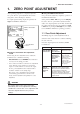
1. ZERO POINT ADJUSTMENT 1. ZERO POINT ADJUSTMENT After operating preparation is completed, adjust the zero point. The zero point adjustment can be made using either of the following two methods. 䊏 Using the HART Communicator Zero point can be adjusted by simple key operation of the HART Communicator. For output signal checking, display the parameter % rnge in the HART Communicator. Select parameter Zero Trim, and press the OK (F4) key twice.
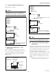
1. ZERO POINT ADJUSTMENT 1.1.1 Using the HART Communicator 1. Device setup 2. Diag/Service (1) Zeroing — Zero trim 3. Calibration 3. Sensor trim NOTE 2. Lower Sensor Trim Zero trim carries out the zero adjustment and sets the input values at present, equal to 0 mmH2O. Use this setting to set LRV = 0 mmH2O. 1 EJA: Apply low pressure (OK) 1. Device setup ABORT OK Check the tank level at present, and press OK (F4). 2. Diag/Service 2 3. Calibration EJA: Press OK when pressure is stable 3.
1. ZERO POINT ADJUSTMENT 1.2 Auto LRV (Change Low Range Value) 1.2.2 Setting the Range Using the Rangesetting Switch With actual pressure(s) being applied to the transmitter, the range-setting switch (push-button) attached to the integral indicator plate and the external zero-adjustment screw allow users to change the lower- and upper-range values for the measurement range (LRV and URV) without the use of a HART Communicator.
1. ZERO POINT ADJUSTMENT IMPORTANT 1. Do not turn off the power to the transmitter immediately after completion of the change in the LRV (and/or URV) setting(s). Note that powering off within thirty seconds after setting will ca use a return to the previous settings. 2. Changing LRV automatically changes URV to the following value. URV previous URV (new LRV previous LRV) 3.
2. HART COMMUNICATOR OPERATION 2. HART COMMUNICATOR OPERATION 2.1 Conditions of Communication Line 2.1.2 Communication Line Requirements Specifications for Communication Line: Supply voltage(general use type); 16.4 to 42 V DC Load resistance; 250 to 600 W (Including cable resistance) Minimum cable size; 24 AWG, (0.
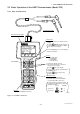
2. HART COMMUNICATOR OPERATION 2.2 Basic Operation of the HART Communicator (Model 275) 2.2.1 Keys and Functions Communication Cable LCD (Liquid crystal display) (21 characters×8 lines) Function keys Functions of the keys are indicated on the display. Pressing (HOME) when the display is as shown changes the display to “Online” menu. (See 2.2.2 “Display”.) EJA:YOKOGAWA Process variables 1 Pres 0.00 mmH2O 2 % rnge 0.00 % 3 A01 Out 4.000mA 4 Snsr temp 37.
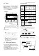
2. HART COMMUNICATOR OPERATION 2.2.2 Display Function Key Labels The HART communicator searches for a transmitter on the 4 to 20mA loop when it is turned on. When the HART communicator is connected to the transmitter, Online menu (Top menu) is started automatically and the following display appears. If no transmitter is found, you select Online menu. Manufacturer’s transmitter type Tag (8 Characters) EJA :YOKOGAWA Online 1 Device setup 2 Pres 0.13 mmH2O 3 A01 Out 4.001 mA 4 LRV 0.
2. HART COMMUNICATOR OPERATION Display When the setting display shown above appears, enter the data as follows: Operation 1 EJA:YOKOGAWA Online 1 Device setup 2 Pres 3 A01 Out 4 LRV 5 URV DEL SET ESC or ENTER Character to be entered Display 1 appears when the HART Communicator is turned on. Select Device setup.
2. HART COMMUNICATOR OPERATION 2.3 Parameters NOTE 2.3.1 Parameter Usage and Selection Do not turn off the transmitter as soon as HART Communicator settings (sending) have been made. If the transmitter is turned of less than 30 seconds after parameters have been set, the set data will not be stored and the terminal returns to previous settings. Before describing the procedure for setting parameters, we present the following table showing how the prameters are used and in what case. Table 2.3.
2. HART COMMUNICATOR OPERATION 2.3.
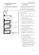
2. HART COMMUNICATOR OPERATION 2.3.3 Setting Parameters 4 (1) Tag No. To change the Tag No., see section 2.2.4 Entering, Setting, and Sending Data. EJA: keypad input 1 LRV 0.00 2 URV 3000.00 3 Unit 4 LSL -3500 5 USL 3500 DEL ESC HELP SEND Up to 8 characters can be set with Tag. The maximum number of characters to be set for other items is as shown below. With Option code /CA, the Descriptor is filled in at the factory as specified in the order.
2. HART COMMUNICATOR OPERATION NOTE 4 EJA: Current applied process value: 500.01 mmH2O 1 Set as 4mA value 2 Read new value 3 Leave as found HELP SEND ABORT ENTER DEL It is possible to set LRV URV. This setting reverses the 4 to 20 mA output signal. Conditions: LSL LRV USL LSL URV USL |URV LRV| Min.
2. HART COMMUNICATOR OPERATION (5) Damping Time Constants The damping constant is set to 2.0 seconds at the factory. When changing the damping constant, proceed as follows: (6) Output Signal Low Cut Mode Setup Low cut can be used on the output signal to stabilize the output near the zero point. The low cut point can be set in a range from 0 to 20% of output. (Hysteresis of cut point: ±1%) Example: To change from 2.0 seconds to 0.2 seconds Either LINEAR or ZERO can be selected as the low cut mode.
2. HART COMMUNICATOR OPERATION (7) Bi-directional Flow Measurement (a) Bi-dir mode enables selection of 50% output at an input of 0 mmH2O. (8) Change Output Limits The range of normal ouput is preset at factory from 5.0 to 110.0% unless otherwise specified or conditioned, and the output is limited with these upper and lower values. This output range can be changed, for example, to meet the requirements of NAMUR, within the settable range.
2. HART COMMUNICATOR OPERATION (10) Integral Indicator Scale Display Mode Display NORMAL % USER SET Related Parameters % rnge 45.6% Example: Set the integral indicator scale to engineering units display Description 1. Device setup Indicates –5 to 110% range depending on the set range (LRV, URV). 4. Detailed setup 4. Display condition Engr disp range Displays values depending on 20.0M 1. Display mode engr disp LRV and engr disp URV Units set using engr disp unit are not indicated.
2. HART COMMUNICATOR OPERATION (11) Unit for Displayed Temperature When the instrument is shipped, the temperature units are set to C (Centigrade). Follow the procedure below to change this setting. Example: Set low range value (LRV) to –50 and upper range value (URV) to 50. 1. Device setup 4. Detailed setup The unit changed here corresponds the unit for Snsr temp. 4. Display condition 3. Engr disp range 2. Engr disp LRV, 3. Engr disp URV Example: Change the unit for the temperature display.
2. HART COMMUNICATOR OPERATION (13) Test Output This feature can be used to output a fixed current from 3.2 mA (–5%) to 21.6 mA (110%) for loop checks. CAUTION 1. Test output is held for approximately 10 minutes, and then released automatically after the time has elapsed. Even if the HART Communicator power supply is turned off or the communication cable is disconnected during test output, it is held for approximately 10 minutes. Example: To output 12 mA (50%) 1. Device setup 2. Diag/Service 2.
2. HART COMMUNICATOR OPERATION (15) Trim Analog Output Fine output adjustment is carried out with D/A trim or Scaled D/A trim. 3 EJA: Press OK when pressure is stable (OK) HELP DEL ABORT OK • D/A Trim D/A trim is to be carried out if the calibration digital ammeter does not read 4.000 mA and 20.000 mA exactly with the output signal of 0% and 100%.
2. HART COMMUNICATOR OPERATION Example 2: To adjust using a voltmeter 6 EJA: Fld dev output 4.000 mA equal to reference meter? 1 Yes 2 No HELP SET ABORT ENTER 1 (ENTER) EJA: Trim analog output 1 D/A trim 2 Scaled D/A trim Ammeter reading: 4.000 Because the reading on the ammeter is 4.000 mA, select YES and press ENTER (F4). If the reading is not 4.000 mA, select item 2. NO. Repeat steps 4 and 5 until the ammeter reads 4.000 mA. 7 Select the Scaled D/A trim item.
2. HART COMMUNICATOR OPERATION (16) Burst Mode The transmitter continuously sends the data stored in it when the burst mode is set on. Either one of measured pressure variable, % output value, or 4 to 20 mA output value can be selected and sent. The data is sent intermittently as a digital signal at 75 ms intervals when the transmitter is set in the burst mode. Therefore, communication by the HART simultaneous communicator is also possible. 9 ‘1 . 0 1’ EJA: Enter meter value 1.
2. HART COMMUNICATOR OPERATION (17) Multidrop Mode “Multidropping” transmitters refers to the connection of several transmitters to a single communications transmission line. Up to 15 transmitters can be connected when set in the multidrop mode. To activate multidrop communication, the transmitter address must be changed to a number from 1 to 15. This change deactivates the 4 to 20 mA analog output, sending it to 4 mA. The alarm current also is disabled.
2. HART COMMUNICATOR OPERATION (19) Software Write Protect EJA configured data is saved by the write protect function. Write protect status is set to YES when 8 alphanumerics are entered in the New password field and transferred to the transmitter. In write protect YES status, the transmitter does not accept parameter changes.
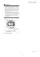
2. HART COMMUNICATOR OPERATION CPU assembly NOTE 1. Enable Wrt 10 min releases Write Protect status for 10 minutes. While Write Protect status is released, enter a new password in the New Password field. It will not be possible to set a new password when 10 minutes have elapsed. 2. To release Write Protect status completely, enter 8 spaces in the New Password field according to the instructions given in (b), Changing the Password. This causes Write Protect status to change from YES to NO.
2. HART COMMUNICATOR OPERATION 2.4 Self-Diagnostics • Error Messages — HART Communicator Error Message 2.4.1 Checking for Problems Pressure sensor error (1) Identify Problems with HART Communicator Self-diagnostics of the transmitter and check of incorrect data setting can be carried out with the HART communicator. There are two methods for selfdiagnosis of the transmitter, self-diagnosis for every transmission and manually executing the SELF TEST command.
2. HART COMMUNICATOR OPERATION (2) Checking with Integral Indicator If an error is detected in the self-diagnostic, an error number is displayed on the integral indicator. If there is more than one error, the error number changes at twosecond intervals. See Table 2.4.1 regarding the error numbers. F0243.EPS Figure 2.4.
3. PARAMETER LISTS 3.
3. PARAMETER LISTS Item Adjustment Sensor information Additional information UHI Description Remarks Zero trim Zero trim Set the current input value to 0 kPa. Lower sensor trim Upper sensor trim Lower sensor trim Upper sensor trim Adjust only measured pressure variable. D/A trim Scaled D/A trim Digital/Analog output trim Scaled D/A trim Adjust the output value at the points of 4 mA and 20 mA.
REVISION RECORD Title: Model EJA Series HART Protocol Manual No.: IM 01C22T01-01E Edition Date Page 1st Nov. 1995 – 2nd Mar. 1998 1 3 2-1 3rd Mar. 2000 – 2-19 4th July 2000 ii 2-6 2-18 3-1 Revised Item New publication 2.1.1 • Add EJA-A Series IM numbers to Table 1. • Add REVISION RECORD • Change the figure of terminal configuration Revised a book in a new format. The location of contents and the associated page numbers may not coincide with the one in old edition. 2.3.