User’s Manual Model EJA Series PROFIBUS PA Communication Type IM 01C22T03-00E IM 01C22T03-00E Yokogawa Electric Corporation 5th Edition
CONTENTS CONTENTS 1. INTRODUCTION ............................................................................................ 1-1 ■ Regarding This Manual ............................................................................. 1-1 1.1 For Safe Use of Product ..................................................................... 1-1 1.2 Warranty .............................................................................................. 1-2 1.3 ATEX Documentation ....................................
CONTENTS 6. CALIBRATION .............................................................................................. 6-1 6.1 6.2 7. Zero-point adjustment ......................................................................... 6-1 Sensor calibration of EJA while applying actual inputs ...................... 6-1 6.2.1 Setting procedure ......................................................................... 6-1 IN-PROCESS OPERATION ....................................................................
1. INTRODUCTION 1. INTRODUCTION This manual contains a description of the DPharp EJA Series Differential Pressure/Pressure Transmitter Fieldbus Communication Type. The Fieldbus communication type is based on the same silicon resonant sensing features as that of the BRAIN communication type, which is employed as the measurement principle, and is similar to the BRAIN communication type in terms of basic performance and operation.
1. INTRODUCTION (a) Installation • The instrument must be installed by an expert engineer or a skilled personnel. The procedures described about INSTALLATION are not permitted for operators. • The use of this instrument is restricted to those who have received appropriate training in the device. • Take care not to create sparks when accessing the instrument or peripheral devices in a hazardous location.
1. INTRODUCTION 1.3 ATEX Documentation SF This procedure is only applicable to the countries in European Union. Kaikkien ATEX Ex -tyyppisten tuotteiden käyttöhjeet ovat saatavilla englannin-, saksan- ja ranskankielisinä. Mikäli tarvitsette Ex -tyyppisten tuotteiden ohjeita omalla paikallisella kielellännne, ottakaa yhteyttä lähimpään Yokogawa-toimistoon tai -edustajaan. GB All instruction manuals for ATEX Ex related products are available in English, German and French.
1.
2. HANDLING CAUTION 2. HANDLING CAUTION 2.1 Installation of an ExplosionProtected Instrument If a customer makes a repair or modification to an intrinsically safe or explosionproof instrument and the instrument is not restored to its original condition, its intrinsically safe or explosionproof construction may be compromised and the instrument may be hazardous to operate. Please contact Yokogawa before making any repair or modification to an instrument.
2. HANDLING CAUTION b. FM Intrinsically Safe Type EJA Series differential, gauge, and absolute pressure transmitters with optional code /FS15.
2. HANDLING CAUTION FISCO Rules The FISCO Concept allows the interconnection of intrinsincally safe apparatus to associated apparatus not specifically examined in such combination.
2. HANDLING CAUTION 2.1.2 CSA Certification Caution for CSA Explosionproof type Note 1. EJA Series differential, gauge, and absolute pressure transmitter with optional code /CF15 are applicable for use in hazardous locations: • Applicable standard: C22.2 No.0, No.0.4, No.25, No.30, No.94, No.142, No.1010.1 • Certificate: 1010820 • Explosionproof for Class I, Division 1, Groups B, C and D. • Dust-ignitionproof for Class II/III, Division 1, Groups E, F and G.
2. HANDLING CAUTION Note 4. Special Conditions for Safe Use • In the case where the enclosure of the Pressure Transmitter is made of aluminium, if it is mounted in an area where the use of category 1 G apparatus is required, it must be installed such, that even in the event of rare incidents, ignition sources due to impact and friction sparks are excluded. Cable The cable used to interconnect the devices needs to comply with the following parameters: Loop resistance Rc: 15...
2. HANDLING CAUTION Number of Devices The number of devices (max. 32) possible on a fieldbus link depends on factors such as the power consumption of each device, the type of cable used, use of repeaters, etc. c. CENELEC ATEX Type of Protection “n” Model EJA Series differential, gauge, and absolute pressure transmitters with optional code /KN25. WARNING b. CENELEC ATEX (KEMA) Flameproof Type Caution for CENELEC (KEMA) Flameproof Type Note 1.
2. HANDLING CAUTION (2) Electrical Connection A mark indicating the electrical connection type is stamped near the electrical connection port. These marks are as follows. (6) Name Plate Name plate T0201.EPS Tag plate for intrinsically safe type 1 Location of the marking No. KEMA 02ATEX1344 X EEx ia C T4 Ui 17.5V Ii 360mA Pi 2.52W Ci 1.76nF Li 0 or Ui 24.0V Ii 250mA Pi 1.2W Ci 1.76nF Li 0 EEx ia B T4 Ui 17.5V Ii 380mA Pi 5.32W Ci 1.76nF Li 0 ENCLOSURE:IP67 Tamb –40 TO 60°C PROCESS TEMP.
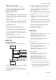
3. ABOUT PROFIBUS PA 3. ABOUT PROFIBUS PA 3.1 Outline 3.4 Wiring System Configuration PROFIBUS PA is a widely used bi-directional digital communication protocol that enables the implementation of technologically advanced process control systems. The EJA Series PROFIBUS PA communication type meets the specifications of PROFIBUS Nutzerorganisation e.V. and is interoperable with devices from Yokogawa and other manufacturers.
4. GETTING STARTED 4. GETTING STARTED PROFIBUS PA is fully dependent upon digital communication protocol and differs in operation from conventional 4 to 20 mA transmission and the BRAIN communication protocol. HMI Class 2 Master FieldMate (FDT/DTM) PDM (EDDL), etc. • DP/PA Couplers: PROFIBUS PA requires DP/PA couplers which convert the RS-485 signals to the IEC 61158-2 signal level and power the field devices via the PROFIBUS PA. • Cable: Refer to Figure 4.1. Table 4.
4. GETTING STARTED 4.2 Master Settings 4.3 Integration of GSD To activate PROFIBUS PA, the following bus parameters must be set for the master. A PROFIBUS PA system requires a GSD file containing device parameters such as the supported transmission rate, input data, output data, data format and data length. The following GSD files are available for the EJA. Table 4.
4. GETTING STARTED 4.4 Engineering Tools 4.4.2 SIMATIC PDM for EDDL Engineering of the EJA PROFIBUS PA can be performed with the following two tools. Electronic Device Description Language (EDDL) defines field device information, and can be used independently of vendors. EDDL files can be read by engineering tools, and the software is used to conduct adjustment, configuration, calibration and tests of devices. 4.4.
4. GETTING STARTED 4.5 Starting FDT frame application The following section describes how to run DTM with FieldMate. For the detailed information on FieldMate, see its User’s manual. Add Communication Path In the Network Configurator window, click [Action] → [Add communication Path]. Enter a description of the communication path and then click [OK]. IMPORTANT Before running the program, log-in to Windows as an Administrator or as a user with administrative authority. Figure 4.
4. GETTING STARTED COMM DTM Configuration In the Network Configurator window, click [Action] → [COMM DTM Configuration]. Running Scan List In the Network Configurator window, click [Action] → [Scan List] → [Scan]. Select the baud rate for the DP/PA coupler (or link). When queried “DTM is disconnected. Do you want to connect now?”, click [Yes]. Click [Defaults] to change the data to the default setting, or enter the desired bus parameters.
4. GETTING STARTED New Device Maintenance Info Click [Action] → [New Device Maintenance Info]. Select [PROFIBUS] → [Yokogawa Electric] → [EJA] → Device Revision Select the corresponding device DTM and then click [Next]. Confirm the information and then click [Finish]. Click [Next]. Figure 4.13 Configuration Figure 4.11 Input Basic Information Choose the communication path from the list and then click [Next].
4. GETTING STARTED Enter the address no. from the scan list, (for example, address 5) in the address field and then press the Enter key. Click [File] → [Save] and then click [File] → [Exit] Figure 4.15 Basic Information Starting DTM Works In the FieldMate window Click [Action] → [DTM] → [Assigned DTM] When queried “Do you want to load DTM parameter from database?”, click [Yes]. Figure 4.16 Starting DTM Works From the DTM Works window, click [Device] → [Connect] Figure 4.
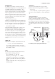
5. CONFIGURATION 5. CONFIGURATION This chapter describes the basic parameters for the three block types and explains how to set and change these parameters. 5.1 Description of Basic Parameters 5.1.1 Physical Block Parameters Physical Block Identification TAG Descriptor Device Serial Number Serial Number Target Mode Diagnosis Diagnosis Diagnosis Extension Write Locking F0501.EPS Figure 5.
5. CONFIGURATION Target Mode: Indicates the AI block mode: Out of Service (O/S), MAN, or AUTO. Target Mode indicates what mode of operation is desired for the AI block. In Out of Service mode, the AI block does not operate. Manual mode does not allow values to be updated. AUTO mode causes the measured values to be updated. Under normal circumstance, set this to AUTO mode. AUTO mode is the factory default.
5. CONFIGURATION Pressure Raw Value Unit: This contains the pressure unit for the calibration values. Temperature Unit: This contains the units of the sensor temperature. Pressure Raw Value: This contains the calibrated sensor value. The unit is derived from pressure raw value unit. Sensor Upper/Lower Limit: These contain the sensor upper/lower limit value. The unit is derived from pressure raw value unit. Upper/Lower Calibration Point: These contain the highest/lowest calibrated value.
5. CONFIGURATION 5.2 Basic Parameter Setting and Changing Table 5.2 Navigation tree structure of online parameters Level of node 1st Process Variable Device Status Diag and Service Easy Setup Calibration Physical Block This section describes basic parameter setting and changing with FieldMate. For detailed information on FieldMate, refer to FieldMate User’s manual. Input Identification Diagnosis Configuration Transducer Block Output Analog Input 1 5.2.
5. CONFIGURATION Example of DTM context screen (a) Process Variables 5.3 Bus Address Setup Every device in PROFIBUS must be assigned a unique address in the range of 0 to 126. If it is not specified at the time of order, ‘126’ is the factory default. Do not change to ‘0’,’1’ or ‘2’ as these are used by master devices. Note: This function is only available if an offline connection to the device is selected.
5. CONFIGURATION Enter [Old Address] to 5 and [New Address] to 20 and Click [Set] Table 5.4 Operation Mode AI Block Automatic (AUTO) Yes Manual (MAN) Yes Out of Service (O/S) Yes “New address successfully set” is displayed in the State field. Transducer Block Yes N/A Yes Physical Block Yes N/A Yes T0504.EPS Click [Close] Refer to the “APPENDIX 1. LIST OF PARAMETERS FOR EACH BLOCK OF THE EJA” for details of the Write Mode for each block. 5.4.1 Tag Number (TAG) Enter the Tag number in TAG.
5. CONFIGURATION Select the desired pressure unit. 5.4.5 Output Scale (Out Scale) and Unit Press the Enter key to confirm the data. Change the Target Mode of Analog Input1 to Out of Service (O/S). AL.23 occurs when the Target Mode is changed to Out of Service (O/S). Select the unit for Out Scale Unit, and press the Enter key to confirm the data. Enter the values configured in Out Scale (Upper/Lower Value), and press the Enter key to confirm the data.
5. CONFIGURATION 5.6 Output Analog Input 1 Setup In the DTM Works window, double-click the [Output] folder. Click the [Analog Input 1] folder. 5.6.1 Fail Safe Mode Fail Safe Mode defines the Output Value and Status (Quality) if a device breaks down. Select Fail Safe Mode, and press the Enter key to confirm the data. When selecting “Default Value is used as Output Value”, enter the desired values for the Fail Safe Default, and press the Enter key to confirm the data. Table 5.
6. CALIBRATION 6. CALIBRATION 6.1 Zero-point adjustment Zero-point adjustment can be performed in two ways. Choose the optimum method in accordance with the circumstances specific to the application employed. The amount of zero-point adjustment changes according to the speed at which the zero-point screw is turned; turn it slowly for fine tuning, or quickly for rough tuning. 6.
7. IN-PROCESS OPERATION 7. IN-PROCESS OPERATION This chapter describes the in-process operation of the EJA 7.1 Mode Transition When each block mode is changed to Out of Service (O/S), the block pauses and a block alarm is issued. When the AI block mode is changed to MAN, the AI block suspends updating of output values. In this case alone, it is possible to write a value and status to the OUT parameter of the block for output. 7.2 Generation of Alarms 7.2.
7. IN-PROCESS OPERATION 7.2.2 Status of Each Parameter in Failure Mode The DTM and EDDL messages when the LCD indicates an alarm are listed in the following table. Table 7.1 Status of each parameter in failure mode Alarm Display AL. 01 Cause of Alarm Capsule Module Failure Transducer Block Pressure/Measured value. Quality =BAD-Sensor Failure Static Pressure/sensor Temperature. Quality=BAD-Sensor Failure AMP Module Failure 1 Pressure/Measured value.
7. IN-PROCESS OPERATION Click [Device] → [Parameter] → [Online] *1: Table 7.2 Fail Safe Mode No. Fail Safe Mode Output Value and Status (Quality) 0 1 2 Fail Safe Default Value Value UNCERTAIN Status (Quality) Substitute Value Last stored valid Value OUT value Storing last valid Output value UNCERTAIN Last Status (Quality) Usable Value wrong calculated The calculated Value value output value is BAD_*(* as incorrect Status (Quality) calculated) Default value is used as output value T0702.
8. DIAGNOSTIC INFORMATION 8. DIAGNOSTIC INFORMATION Diagnostic information and failures of EJA are indicated by using parameter Diagnosis and Diagnosis Extension in the Physical Block. Diagnosis and Diagnosis Extension are listed in Table 8.1 and 8.2 below. Table 8.1 Contents of DIAGNOSIS Octet Bit 0 Mnemonic DIA_HW_ELECTR Description 3 4 Support*1 Hardware failure: electronics -- 1 1 1 DIA_HW_MECH Hardware failure: mechanical Capsule Module Failure1 (AL.01) Capsule Module Failure2 (AL.
8. DIAGNOSTIC INFORMATION Table 8.2 Contents of DIAGNOSIS_EXTENSION category Display Message Countermeasure Message Alarm description Octet Bit Capsule module failure. 4 0 Capsule Module Failure1 (AL.01) Replace capsule. Capsule Module Failure2 (AL.01) Replace capsule. Capsule module failure. 4 1 Capsule Module Failure3 (AL.01) Replace capsule. Capsule memory failure. 4 4 AMP Module Failure1 (AL.02) Replace amplifier. Amp memory failure. 4 5 AMP Module Failure2 (AL.
9. GENERAL SPECIFICATIONS 9. GENERAL SPECIFICATIONS 9.1 Standard Specifications 9 to 24 V DC for intrinsically safe type Entity model 9 to 17.5 V DC for intrinsically safe type FISCO model For items other than those described below, refer to the corresponding General Specification sheet. Conditions of Communication Line: Supply Voltage: 9 to 32 V DC Current Draw: 16.
9. GENERAL SPECIFICATIONS 9.2 Optional Specifications For items other than those described below, refer to the appropriate user’s manual. Item Factory Mutual (FM) CENELEC ATEX Canadian Standards Association (CSA) Description Code FM Explosionproof Approval *1 Explosionproof for Class I, Division 1, Groups B, C and D Dust-ignitionproof for Class II/III, Division 1, Groups E, F and G Hazardous (classified) locations, indoors and outdoors (NEMA 4X) Temperature class: T6 Amb. Temp.
APPENDIX 1. LIST OF PARAMETERS FOR EACH BLOCK OF THE EJA APPENDIX 1. LIST OF PARAMETERS FOR EACH BLOCK OF THE EJA Note: O/S: MAN: AUTO: --: The Write Mode column indicates the mode in which the parameter is write enabled. Write enabled in O/S mode. Write enabled in manual mode. Write enabled in auto mode, manual mode, and O/S mode. Read only. A1.
APPENDIX 1. LIST OF PARAMETERS FOR EACH BLOCK OF THE EJA Index 34 Parameter Write Locking Write Mode Initial Value Description AUTO Off If set, no writes from anywhere are allowed, except to clear WRITE_LOCKING. on/off 35 Factory Reset AUTO Factory Reset Allows a manual restart to be initiated. Factory Reset: Resetting device for default values. The bus address setting remains the same. Warm Start: Warm start of the device. All parameterization remains unchanged.
APPENDIX 1. LIST OF PARAMETERS FOR EACH BLOCK OF THE EJA A1.2 AI Function Block Parameter List (AI1: Slot=1 Index Parameter Write Mode Initial Value AI2: Slot=2) Description Information on this block such as Block Tag, DD Revision, Execution Time etc. 16 Block Object -- 17 Static Revision No -- 18 TAG AUTO Space The user description of the intended application of the block. 19 Strategy AUTO 0 The strategy field can be used to identify grouping of blocks.
APPENDIX 1. LIST OF PARAMETERS FOR EACH BLOCK OF THE EJA Index Parameter Write Mode Initial Value Description 48 Lower Limit Warning -- For future use. 49 Lower Limit Alarm -- For future use. 50 Simulation AUTO Disbled For commissioning and test purposes the input value from the Transducer Block in the Analog Input Function Block AI-FB can be modified. That means that the Transducer and AI-FB will be disconnected.
APPENDIX 1. LIST OF PARAMETERS FOR EACH BLOCK OF THE EJA A1.3 Transducer Block Parameter List (Slot=3) Index Parameter Write Mode Initial Value Description Information on this block such as Block Tag, DD Revision, Execution Time. 16 Block Object -- 17 Static Revision No -- 18 TAG AUTO Space The user description of the intended application of the block. 19 Strategy AUTO 0 The strategy field can be used to identify a grouping of blocks. This data is not checked or processed by the block.
APPENDIX 1. LIST OF PARAMETERS FOR EACH BLOCK OF THE EJA Index Parameter Write Mode Initial Value Description 46 Pressure Unit O/S Specified at the time of order This parameter contains the pressure units of the Pressure Value.
APPENDIX 2. LIST OF DTM MENU APPENDIX 2. LIST OF DTM MENU Ist node 2nd node Process Variable Label for node and parameter 3rd node 1st Parameter Ist node Input 2nd node Label for node and parameter 3rd node 1st Parameter Transducer Block Pressure Raw Value Pressure Value Measured Value Static Pressure Sensor Tempareture AI1 Output Value AI2 Output Value Static Revision No.
APPENDIX 3. LIST OF PDM (EDDL) MENU APPENDIX 3. LIST OF PDM (EDDL) MENU EJA Easy Setup Output Function Block 1 - Analog Input Static Revision No.
REVISION RECORD Title: Model EJA Series PROFIBUS PA Communication Type Manual No.: IM 01C22T03-00E Edition Date Page 1st Nov. 2004 - Revised Item 2nd July 2006 1-2 2-3 3rd June 2007 4th Jan. 2008 9-2 9.2 • Delete applicable standard from the table. 5th Oct. 2008 2-9 9-1 9-2 2.9.4 9.1 9.2 • Change explosion protection marking for type n from EEX to Ex • Add EMC conformity Standards • Add sealing statement for CSA certification New publication 1.1 2.1.