User’s Manual Model EJA Series Fieldbus Communication Type IM 01C22T02-01E IM 01C22T02-01E Yokogawa Electric Corporation 10th Edition
CONTENTS CONTENTS 1. INTRODUCTION ............................................................................................ 1-1 Regarding This Manual ................................................................................. 1-1 1.1 For Safe Use of Product ..................................................................... 1-1 1.2 Warranty .............................................................................................. 1-2 1.3 ATEX Documentation ..................................
CONTENTS 6. IN-PROCESS OPERATION .......................................................................... 6-1 6.1 6.2 Mode Transition .................................................................................. 6-1 Generation of Alarm ............................................................................ 6-1 6.2.1 Indication of Alarm ....................................................................... 6-1 6.2.2 Alarms and Events ...........................................................
CONTENTS A4.12 External-output Tracking ................................................................... A-19 A4.13 Measured-value Tracking .................................................................. A-19 A4.14 Initialization and Manual Fallback (IMan) ......................................... A-20 A4.15 Manual Fallback ................................................................................ A-20 A4.16 Auto Fallback .........................................................................
1. INTRODUCTION 1. INTRODUCTION This manual contains a description of the DPharp EJA Series Differential Pressure/Pressure Transmitter Fieldbus Communication Type. The Fieldbus communication type is based on the same silicon resonant sensing features as that of the BRAIN communication type, which is employed as the measurement principle, and is similar to the BRAIN communication type in terms of basic performance and operation.
1. INTRODUCTION (a) Installation • The instrument must be installed by an expert engineer or a skilled personnel. The procedures described about INSTALLATION are not permitted for operators. • The use of this instrument is restricted to those who have received appropriate training in the device. • Take care not to create sparks when accessing the instrument or peripheral devices in a hazardous location.
1. INTRODUCTION 1.3 ATEX Documentation SF This procedure is only applicable to the countries in European Union. Kaikkien ATEX Ex -tyyppisten tuotteiden käyttöhjeet ovat saatavilla englannin-, saksan- ja ranskankielisinä. Mikäli tarvitsette Ex -tyyppisten tuotteiden ohjeita omalla paikallisella kielellännne, ottakaa yhteyttä lähimpään Yokogawa-toimistoon tai -edustajaan. GB All instruction manuals for ATEX Ex related products are available in English, German and French.
1.
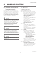
2. HANDLING CAUTION 2. HANDLING CAUTION 2.1.1 FM approval 2.1 Installation of an ExplosionProtected Instrument a. FM Explosionproof Type Caution for FM Explosionproof type If a customer makes a repair or modification to an intrinsically safe or explosionproof instrument and the instrument is not restored to its original condition, its intrinsically safe or explosionproof construction may be compromised and the instrument may be hazardous to operate.
2. HANDLING CAUTION b. FM Intrinsically Safe Type EJA Series differential, gauge, and absolute pressure transmitters with optional code /FS15.
2. HANDLING CAUTION FISCO Rules The FISCO Concept allows the interconnection of intrinsincally safe apparatus to associated apparatus not specifically examined in such combination.
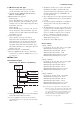
2. HANDLING CAUTION Installation Diagram (Nonincendive, Division 2 Installation) Terminator Vmax = 32 V Ci = 3.52 nF Li = 0 H Pressure Transmitter Field Instruments Field Instruments Hazardous Location Non-Hazardous Location (Nonincendive) Power Supply FM Approved Associated Nonincendive Field Wiring Apparatus Vt or Voc It or Isc Ca La F0206.EPS *1: Dust-tight conduit seal must be used when installed in Class II and Class III environments.
2. HANDLING CAUTION 2: Installation should be in accordance with National Electrical Code (ANSI/NFPA 70) Sections 504, 505 and Local Electrical Code. 3: The configuration of Associated Apparatus must be Factory Mutual Research Approved. 4: Associated Apparatus manufacturer’s installation drawing must be followed when installing this equipment. 5: No revision to drawing without prior Factory Mutual Research Approval. 6: Terminator and supply unit must be FM approved.
2. HANDLING CAUTION • Process Temperature: 120°C max. • Ambient Temperature: –40 to 60°C Note 2. Installation • All wiring shall comply with local installation requirements. (Refer to the installation diagram) Note 3. Maintenance and Repair • The instrument modification or parts replacement by other than authorized representative of Yokogawa Electric Corporation is prohibited and will void KEMA Intrinsically safe Certification. Note 4.
2. HANDLING CAUTION I.S. values Power supply-field device: Po Pi, Uo Ui, Io Ii Calculation of max. allowed cable length: Ccable Co - ∑Ci - ∑Ci (Terminator) Lcable Lo - ∑Li Note 5. Maintenance and Repair • The instrument modification or parts replacement by other than authorized representative of Yokogawa Electric Corporation is prohibited and will void KEMA Flameproof Certification. Number of Devices The number of devices (max.
2. HANDLING CAUTION Note 3. Maintenance and Repair • The instrument modification or parts replacement by other than authorized representative of Yokogawa Electric Corporation is prohibited and will void Type of Protection “n”. (3) Installation WARNING • All wiring shall comply with local installation requirements and the local electrical code. • There is no need for a conduit seal in Division 1 and Division 2 hazardous locations because this product is sealed at factory. Vmax = 32 Vdc Ci = 3.
2. HANDLING CAUTION (6) Name Plate 2.1.4 Name plate IECEx Certification a. IECEx Flameproof Type Caution for IECEx flameproof type. Tag plate for intrinsically safe type 1 No. KEMA 02ATEX1344 X EEx ia C T4 Ui 17.5V Ii 360mA Pi 2.52W Ci 1.76nF Li 0 or Ui 24.0V Ii 250mA Pi 1.2W Ci 1.76nF Li 0 EEx ia B T4 Ui 17.5V Ii 380mA Pi 5.32W Ci 1.76nF Li 0 ENCLOSURE:IP67 Tamb –40 TO 60°C PROCESS TEMP. 120°C KS25 Tag plate for flameproof type F0298.EPS MODEL: Specified model code. STYLE: Style code.
3. ABOUT FIELDBUS 3. ABOUT FIELDBUS 3.1 Outline Fieldbus is a bi-directional digital communication protocol for field devices, which offers an advancement in implementation technologies for process control systems and is widely employed by numerous field devices. EJA Series Fieldbus communication type employs the specification standardized by The Fieldbus Foundation, and provides interoperability between Yokogawa devices and those produced by other manufacturers.
4. GETTING STARTED 4. GETTING STARTED Fieldbus is fully dependent upon digital communication protocol and differs in operation from conventional 4 to 20 mA transmission and the BRAIN communication protocol. It is recommended that novice users use field devices in accordance with the procedures described in this section. The procedures assume that field devices will be set up on a bench or in an instrument shop. Refer to Yokogawa when making arrangements to purchase the recommended equipment.
4. GETTING STARTED 4.2 Host Setting 0x00 To activate Fieldbus, the following settings are required for the host. 0x0F 0x10 Not used 0x13 0x14 Bridge device LM device V(FUN) IMPORTANT Unused Do not turn off the power immediately after setting. When the parameters are saved to the EEPROM, the redundant processing is executed for an improvement of reliability.
4. GETTING STARTED 4.3 Bus Power ON 4.4 Integration of DD Turn on the power of the host and the bus. Where the EJA is equipped with an LCD indicator, first all segments are lit, then the display begins to operate. If the indicator is not lit, check the polarity of the power supply. If the host supports DD (Device Description), the DD of the EJA needs to be installed. Check if host has the following directory under its default DD directory.
4. GETTING STARTED 4.6 Continuous Record of Values If the host has a function of continuously records the indications, use this function to list the indications (values). Depending on the host being used, it may be necessary to set the schedule of Publish (the function that transmits the indication on a periodic basis). 4.7 Generation of Alarm If the host is allowed to receive alarms, generation of an alarm can be attempted from EJA. In this case, set the reception of alarms on the host side.
5. CONFIGURATION 5. CONFIGURATION This chapter describes how to adapt the function and performance of the EJA to suit specific applications. Because multiple devices are connected to Fieldbus, it is important to carefully consider the device requirements and settings when configuring the system. The following steps must be taken. (1)Network design Determines the devices to be connected to Fieldbus and checks the capacity of the power supply.
5. CONFIGURATION range of the BASIC device. When the EJA is used as Link Master, place the EJA in the range of LM device. Set the range of addresses to be used to the LM device. Set the following parameters. Table 5.2 Operation Parameter Values of the EJA to be Set to LM Devices Symbol V (ST) Parameters Slot-Time Table 5.
5. CONFIGURATION A maximum of 100 ms is taken for execution of AI block. For scheduling of communications for combination with the next function block, the execution is so arranged as to start after a lapse of longer than 100 ms. In no case should two AI function blocks of the EJA be executed at the same time (execution time is overlapped). Figure 5.3 shows an example of schedule based on the loop shown in Figure 5.2. 5.
5. CONFIGURATION 5.5 Communication Setting Table 5.4 VCR Static Entry Subindex To set the communication function, it is necessary to change the database residing in System/network Management VFD. Parameter Description 1 FasArTypeAndRole Indicates the type and role of communication (VCR). The following 4 types are used for EJA. 0x32: Server (Responds to requests from host.) 0x44: Source (Transmits alarm or trend.) 0x66: Publisher (Sends AI block output to other blocks.
5. CONFIGURATION Subindex Parameter 5.6 Block Setting Description Set the parameter for function block VFD. 12 FasDllSubsriberTime WindowSize 13 FasDllSubscriber Not used for EJA. SynchronizationDlcep 14 FmsVfdId Sets VFD for EJA to be used. 0x1: System/network management VFD 0x1234: Function block VFD 15 FmsMaxOutstanding ServiceCalling Set 0 to Server. It is not used for other applications. 16 FmsMaxOutstanding ServiceCalled Set 1 to Server. It is not used for other applications.
5. CONFIGURATION 5.6.2 Trend Object SMIB (System Resource Transducer Management AI1 OUT AI2 OUT block block Information Base) It is possible to set the parameter so that the function block automatically transmits Trend. EJA has five Trend objects, four of which are used for Trend in analog mode parameters and one is used for Trend in discrete mode parameter. A single Trend object specifies the trend of one parameter.
5. CONFIGURATION Relative Parameter Mnemonic VIEW VIEW VIEW VIEW Index 1 2 3 4 11 DEV_TYPE 2 12 DEV_REV 1 13 DD_REV 1 14 GRANT_DENY 15 HARD_TYPES 16 Table 5.
5. CONFIGURATION 5.6.4 Function Block Parameters Table 5.13 View Object for AI1.
5. CONFIGURATION PV_FTIME: Sets the time constant of the damping function within AI block (primary delay) in seconds. OUT_SCALE: Sets the range of output (from 0% to 100%). The unit can also be set with ease. Alarm Priority: Indicates the priority of the process alarm. If a value of 3 or greater is set, an alarm is transmitted. The factory default is 0. Four types of alarm can be set: HI_PRI, HI_HI_PRI, LO_PRI, and LO_LO_PRI. Alarm Threshold: Sets the threshold at which a process alarm is generated.
6. IN-PROCESS OPERATION 6. IN-PROCESS OPERATION This chapter describes the procedure performed when changing the operation of the function block of the EJA in process. Table 6.1 List of Error Messages LCD Content of Alarms AL.01 Capsule module failure. AL.02 AMP module failure (1). AL.03 AMP module failure (2). AL.20 AI1 block is not scheduled. AL.21 The resource block is in O/S mode. AL.22 The transducer block is in O/S mode. AL.23 AI1 function block is in O/S mode. AL.
6. IN-PROCESS OPERATION Update Alerts (Generated when a important (restorable) parameter is updated) By Resource Block Update Event By Transducer Block Update Event By AI1 Block Update Event By AI2 Block Update Event By PID Block Update Event In simulation enabled status, an alarm is generated from the resource block, and other device alarms will be masked; for this reason the simulation must be disabled immediately after using this function.
7. DEVICE STATUS 7. DEVICE STATUS Device setting status and failures of EJA are indicated by using parameter DEVICE_STATUS_1, DEVICE_STATUS_2 and DEVICE_STATUS_3 (index 1045, 1046 and 1047) in Resource Block. Table 7.1 Contents of DEVICE_STATUS_1 (index 1045) Hexadecimal Display through DD Table 7.
7. DEVICE STATUS Table 7.3 Contents of DEVICE_STATUS_3 (index 1047) Hexadecimal Display through DD Description 0x80000000 0x40000000 0x20000000 0x10000000 0x08000000 Transducer Block is in O/S mode (AL.22) Transducer Block is in O/S mode. 0x04000000 0x02000000 0x01000000 0x00800000 0x00400000 0x00200000 0x00100000 0x00080000 0x00040000 0x00020000 0x00010000 0x00008000 0x00004000 Simulation is enabled in AI2 Function Block is in Simulation mode.
8. GENERAL SPECIFICATIONS 8. GENERAL SPECIFICATIONS 8.1 Standard Specifications For items other than those described below, refer to each User’s Manual. Applicable Model: All DPharp EJA series Output Signal: Digital communication signal based on FOUNDATION fieldbus protocol. Supply Voltage 9 to 32 V DC for general use, flameproof type, and nonincendive type 9 to 24 V DC for intrinsically safe type Entity model 9 to 17.
8. GENERAL SPECIFICATIONS 8.2 Optional Specifications For items other than those described below, refer to each User’s Manual. Item Factory Mutual (FM) CENELEC ATEX (KEMA) IECEx Scheme Description Code FM Explosionproof Approval *1 Explosionproof for Class I, Division 1, Groups B, C and D Dust-ignitionproof for Class II/III, Division 1, Groups E, F and G Hazardous (classified) locations, indoors and outdoors (NEMA 4X) Temperature class: T6 Amb. Temp.
8. GENERAL SPECIFICATIONS Item Canadian Standards Association (CSA) Description Code CSA Explosionproof Approval *5 Certificate: 1010820 Explosionproof for Class I, Division 1, Groups B, C and D Dustignitionproof for Class II/III, Division 1, Groups E, F and G Temp. Class: T4, T5, T6 Encl Type 4x Amb. Temp.: –40 to 80°C (–40 to 176°F) Max. Process Temp.
APPENDIX 1. LIST OF PARAMETERS FOR EACH BLOCK OF THE EJA APPENDIX 1. LIST OF PARAMETERS FOR EACH BLOCK OF THE EJA Note: O/S: MAN: AUTO: The Write Mode column contains the modes in which each parameter is write enabled. Write enabled in O/S mode. Write enabled in Man mode and O/S mode. Write enabled in Auto mode, Man mode, and O/S mode. A1.
APPENDIX 1. LIST OF PARAMETERS FOR EACH BLOCK OF THE EJA Factory Default Relative Index Parameter Name Index Write Mode AUTO Explanation Used to select resource block options defined in FEATURES. bit0: Scheduled bit1: Event driven bit2: Manufacturer specified 18 1018 FEATURE_SEL Soft write lock supported Report supported 19 1019 CYCLE_TYPE Scheduled – Identifies the block execution methods available for this resource.
APPENDIX 1. LIST OF PARAMETERS FOR EACH BLOCK OF THE EJA Factory Default Relative Index Parameter Name Index Write Mode Explanation 46 1046 DEVICE_STATUS_2 0 – Device status (failure or setting error etc.) 47 1047 DEVICE_STATUS_3 0 – Device status (function block setting.) 48 1048 DEVICE_STATUS_4 0 – Not used for EJA. Not used for EJA. 49 1049 DEVICE_STATUS_5 0 – 50 1050 DEVICE_STATUS_6 0 – Not used for EJA. 51 1051 DEVICE_STATUS_7 0 – Not used for EJA.
APPENDIX 1. LIST OF PARAMETERS FOR EACH BLOCK OF THE EJA Relative Index Index AI2 Parameter Name Index AI1 Factory Default Write Mode Explanation 14 4014 4114 STATUS_OPTS 0 O/S Options which the user may select in the block processing of status 15 4015 4115 CHANNEL AI1: 1 AI2: 2 O/S The number of the logical hardware channel that is connected to this I/O block. This information defines the transducer to be used going to or from the physical world.
APPENDIX 1. LIST OF PARAMETERS FOR EACH BLOCK OF THE EJA A1.3 Transducer Block Relative Index Parameter Name Index Factory Default Write Mode Explanation 0 2000 Block Header TAG: “TB” Block Tag = O/S Information on this block such as Block Tag, DD Revision, Execution Time etc. 1 2001 ST_REV – – The revision level of the static data associated with the function block. The revision value will be incremented each time a static parameter value in the block is changed.
APPENDIX 1. LIST OF PARAMETERS FOR EACH BLOCK OF THE EJA Relative Index Parameter Name Index Factory Default Write Mode Explanation 22 2022 SENSOR_SN Serial No. – Serial number. 23 2023 SENSOR_CAL_ METHOD 103: factory trim standard calibration O/S The method of the last sensor calibration.
APPENDIX 2. APPLICATION, SETTING AND CHANGE OF BASIC PARAMETERS APPENDIX 2. APPLICATION, SETTING AND CHANGE OF BASIC PARAMETERS A2.1 Applications and Selection of Basic Parameters Setting Item (applicable parameters) Summary Tag No. (PD_TAG) Sets PD Tag and each block tag. Up to 32 alphanumeric characters can be set for both tags. Refer to “Tag and address” in Section 5.4.
APPENDIX 2. APPLICATION, SETTING AND CHANGE OF BASIC PARAMETERS A2.2 Setting and Change of Basic Parameters Refer to the “List of parameters for each block of the EJA” for details of the Write Mode for each block. This section describes the procedure taken to set and change the parameters for each block. Obtaining access to each parameter differs depending on the configuration system used. For details, refer to the instruction manual for each configuration system.
APPENDIX 2. APPLICATION, SETTING AND CHANGE OF BASIC PARAMETERS Restrictions imposed when the device is equipped with a built-in indicator. When the output mode (L_TYPE) is set as Indirect or IndirectSQRT, the range determined by the output scale corresponds to the scale and unit of the indicator. Set the lower and higher value of the range (numeric string excluding decimal point if the decimal point is included) in a range of –19999 to 19999. Down to the third decimal position can be set.
APPENDIX 2. APPLICATION, SETTING AND CHANGE OF BASIC PARAMETERS A2.4 Setting the AI2 Function Block The AI2 function block outputs the static pressure signals. (3)Range change while applying actual inputs It is possible to calibrate the sensor by applying the actual inputs to low-pressure and high-pressure points. Apply the pressure to the low-pressure point from the pressure standard.
APPENDIX 2. APPLICATION, SETTING AND CHANGE OF BASIC PARAMETERS (a) Perform the following procedure to set the current output value to 0%. Turning the screw clockwise causes the output value to increase while turning it counterclockwise causes the output to decrease; zero-point can be adjusted with a resolution of 0.001% of URV. The amount of zero-point adjustment changes according to the speed at which the zero- adjustment screw is turned; turn it slowly for fine tuning, or quickly for coarse tuning.
APPENDIX 3. OPERATION OF EACH PARAMETER IN FAILURE MODE APPENDIX 3. OPERATION OF EACH PARAMETER IN FAILURE MODE • Following table summarizes the value of EJA parameters when LCD display indicates an Alarm. (1) ALARM Display Cause of Alarm AL. 01 Capsule Module Failure Resource Block – Transducer Block BLOCK_ERR=Input Failure Function Block – XD_ERROR= Mechanical Failure AL. 02 AMP Module Failure 1 – PV. STATUS=BAD: Sensor Failure PV. STATUS=BAD: Sensor Failure SV.
APPENDIX 3. OPERATION OF EACH PARAMETER IN FAILURE MODE • Following table summarizes the value of EJA parameters when LCD display indicates an Alarm. (2) ALARM Display Cause of Alarm AL. 23 AI1 Function Block is in O/S mode Resorce Block – Transducer Block – Function Block BLOCK_ERR=Out Of Service PV. STATUS=HOLD OUT. STATUS=BAD: Out of Service AL. 41 AL. 42 AL.
APPENDIX 4. PID Block APPENDIX 4. PID BLOCK A PID block performs the PID control computation based on the deviation of the measured value (PV) from the setpoint (SV), and is generally used for constant-setpoint and cascaded-setpoint control. A4.1 Function Diagram The figure below depicts the function diagram of a PID block.
APPENDIX 4. PID Block A4.3 Parameters of PID Block NOTE: In the table below, the Write column shows the modes in which the respective parameters can be written. A blank in the Write column indicates that the corresponding parameter can be written in all modes of the PID block. A dash (-) indicates that the corresponding parameter cannot be written in any mode. Parameter Name Index Default (factory setting) Write Valid Range Description Same as that for an AI block.
APPENDIX 4. PID Block Index Parameter Name Default Write (factory setting) Valid Range Description 34 SHED_OPT 0 35 RCAS_OUT 0 --- Remote setpoint sent to a computer, etc. 36 ROUT_OUT 0 --- Remote control output value 37 TRK_SCALE 100 0 1342 1 MAN 38 TRK_IN_D 0 Switch for output tracking. See Section A4.12 for details. 39 TRK_VAL 0 Output tracking value (TRK_VAL) When MODE_BLK.actual = LO, the value scaled from the TRK_VAL value is set in OUT.
APPENDIX 4. PID Block A4.4 PID Computation Details A4.5 Control Output A4.4.1PV-proportional and -derivative Type PID (I-PD) Control Algorithm The final control output value, OUT, is computed based on the change in control output ∆MVn, which is calculated at each control period in accordance with the aforementioned algorithm. The PID block in an EJA performs the velocity type output action for the control output.
APPENDIX 4. PID Block A4.8 Feed-forward Block Mode Feed-forward is an action to add a compensation output signal FF_VAL to the output of the PID control computation, and is typically used for feed-forward control. The figure below illustrates the action. Description IMan Initialization and manual mode, in which the control action is suspended. The PID block enters this mode when the specified condition is met (see Section A4.14).
APPENDIX 4. PID Block A4.10 Bumpless Transfer A4.12 External-output Tracking Prevents a sudden change in the control output OUT at changes in block mode (MODE_BLK) and at switching of the connection from the control output OUT to the cascaded secondary function block. The action to perform a bumpless transfer differs depending on the MODE_BLK values. External tracking is an action of outputting the value of the remote output TRK_VAL set from outside the PID block, as illustrated in the figure below.
APPENDIX 4. PID Block Options in CONTROL_OPTS A4.15 Manual Fallback Description Bypass Enable This parameter allows BYPASS to be set. SP-PV Track in Man Equalizes SP to PV when MODE_BLK.target is set to Man. SP-PV Track in ROut Equalizes SP to PV when MODE_BLK.target is set to ROut. SP-PV Track in LO or IMan Equalizes SP to PV when actual is set to LO or IMAN. SP-PV Track retained Target Equalizes SP to RCAS_IN when MODE_ BLK.target is set to RCas, and to CAS_IN when MODE_BLK.
APPENDIX 4. PID Block A4.17 Mode Shedding upon Computer Failure When the data status of RCAS_IN or ROUT_IN, which is the setting received from a computer as the setpoint SP, falls to Bad while the PID block is running in the RCas or ROut mode, the mode shedding occurs in accordance with the settings in SHED_OPT. If the RCAS_IN data is not renewed within the time specified by SHED_RCAS in resource block, the data status of RCAS_IN falls to Bad. A4.17.
APPENDIX 4. PID Block A4.19 Example of Block Connections A4.19.1 View Object for PID Function Block VIEW VIEW VIEW VIEW Relative Parameter Mnemonic 1 2 3 Index 4 AI OUT IN PID BKCAL_IN OUT CAS_IN AO BKCAL_OUT FA0406.EPS When configuring a simple PID control loop by combining an EJA transmitter with a fieldbus valve positioner that contains an AO block, follow the procedure below to make the settings of the corresponding fieldbus function blocks: 1.
APPENDIX 4.
APPENDIX 5. Link Master Functions APPENDIX 5. LINK MASTER FUNCTIONS A5.1 Link Active Scheduler A link active scheduler (LAS) is a deterministic, centralized bus scheduler that can control communications on an H1 fieldbus segment. There is only one LAS on an H1 fieldbus segment. An EJA supports the following LAS functions. • PN transmission: Identifies a fieldbus device newly connected to the same fieldbus segment. PN is short for Probe Node.
APPENDIX 5. Link Master Functions A5.3 Transfer of LAS There are two procedures for an LM to become the LAS: • If the LM whose value of [V(ST)!V(TN)] is the smallest on a segment, with the exception of the current LAS, judges that there is no LAS on the segment, in such a case as when the segment has started up or when the current LAS has failed, the LM declares itself as the LAS, then becomes the LAS. (With this procedure, an LM backs up the LAS as shown in the following figure.
APPENDIX 5. Link Master Functions A5.4 LM Functions No. Function Description 1 LM initialization When a fieldbus segment starts, the LM with the smallest [V(ST) × V(TN)] value within the segment becomes the LAS. At all times, each LM is checking whether or not a carrier is on the segment. 2 Startup of other nodes (PN and Node Activation SPDU transmissions) Transmits a PN (Probe Node) message, and Node Activation SPDU message to devices which return a new PR (Probe Response) message.
APPENDIX 5. Link Master Functions A5.5 LM Parameters A5.5.1 LM Parameter List The tables below show LM parameters of an EJA transmitter.
APPENDIX 5.
APPENDIX 5. Link Master Functions A5.5.2 Descriptions for LM Parameters The following describes LM parameters of an EJA transmitter. NOTE: Do not turn off the power to the EJA for 60 seconds after making a change to its parameter settings.
APPENDIX 5. Link Master Functions (8) DlmeBasicInfo Subindex (11) PlmeBasicInfo Size [bytes] Element 1 SlotTime 2 Indicates the capability value for V(ST) of the device. 2 PerDlpduPhlOverhead 1 V(PhLO) 3 MaxResponseDelay 1 Indicates the capability value for V(MRD) of the device. 4 ThisNode 1 V(TN), node address 5 ThisLink 2 V(TL), link-id 6 MinInterPduDelay 1 Indicates the capability value for V(MID) of the device.
APPENDIX 5. Link Master Functions Subindex Element Size [bytes] Q3. Description 1 Version 2 Indicates the version number of the LAS schedule downloaded to the corresponding domain. 2 Macrocycle Duration 4 Indicates the macro cycle of the LAS schedule downloaded to the corresponding domain. 3 TimeResolution 2 Indicates the time resolution that is required to execute the LAS schedule downloaded to the corresponding domain. TA0514.
APPENDIX 6. SOFTWARE DOWNLOAD APPENDIX 6. SOFTWARE DOWNLOAD A6.1 Benefits of Software Download This function enables you to download software to field devices via a FOUNDATION fieldbus to update their software. Typical uses are to add new features such as function blocks and diagnostics to existing devices, and to optimize existing field devices for your plant. Update Program New Diagnostics I/O PID AI Figure 1. AI Concept of Software Downloading A6.2 Specifications Steady-state current: Max. 16.
APPENDIX 6. SOFTWARE DOWNLOAD CAUTION NOTE The current dissipation of the target field device increases transitorily immediately after a download due to erasing of the FlashROM’s contents. Use a fieldbus power supply which has sufficient capacity to cover such increases in feed current. The download tool can not execute downloading during other system connects to the system/ network management VFD of the device. A6.
APPENDIX 6. SOFTWARE DOWNLOAD The device type is “0008” for an EJA transmitter (with software download capability). The software name is “ORIGINAL” or “UPDATE.” The former indicates an original file and the latter an update file. Whenever performing a download to update the device revision, obtain the original file. In general, an addition to the parameters or blocks requires a device revision update. A6.
APPENDIX 6. SOFTWARE DOWNLOAD A6.7 Troubleshooting For error messages appearing in the download tool, see also the User’s Manual of download tool. Table 2. Actions after Software Update Symptom Cause Remedy An error occurs before starting a download, disabling the download. The selected download file is not for the selected field device. Check SOFTDWN_ERROR in the resource block and obtain the correct file. An error occurs after starting a download, disabling the download.
APPENDIX 6. SOFTWARE DOWNLOAD Table 4.
APPENDIX 6. SOFTWARE DOWNLOAD A6.9 View Objects Altered by Software Download (1) Resource Block Relative Index Parameter Name VIEW VIEW VIEW VIEW 1 2 3 4 53 SOFTDWN_PROTECT 1 54 SOFTDWN_FORMAT 1 55 SOFTDWN_COUNT 56 SOFTDWN_ACT_AREA 1 57 SOFTDWN_MOD_REV 16 58 SOFTDWN_ERROR 2 Total bytes 2 22 30 73 35 TA0605.EPS (2) Transducer Block Relative Index 55 Parameter Name VIEW 1 VIEW 2 TEST_18 Total bytes VIEW 3 VIEW 4 1 34 21 35 116 TA0607.
APPENDIX 6. SOFTWARE DOWNLOAD A6.10 System/Network Management VFD Parameters Relating to Software Download Table 5. System/Network Management VFD Parameters Write Mode: R/W = read/write; R = read only Index (SM) 400 410 420 430 440 Parameter Name DWNLD_PROPERTY Sub Index Default (Factory Set) Sub-parameter Name DOMAIN_HEADER.
APPENDIX 6. SOFTWARE DOWNLOAD A6.11 Comments on System/Network Management VFD Parameters Relating to Software Download IMPORTANT Do not turn off the power to a field device immediately after changing parameter settings. Data writing actions to the EEPROM are made redundant to ensure reliability. If the power is turned off within 60 seconds after setup, the parameters may revert to the previous settings.
APPENDIX 6. SOFTWARE DOWNLOAD (2) DOMAIN_DESCRIPTOR Sub Element Index 1 Size 1 Command Description (Bytes) Reads/writes software download commands. 1: PREPARE_FOR_DWNLD (instruction of download preparation) 2: ACTIVATE (activation instruction) 3: CANCEL_DWNLD (instruction of download cancellation) State 2 1 Indicates the current download status.
REVISION RECORD Title: Model EJA Series Fieldbus Communication Type Manual No.: IM 01C22T02-01E Edition Date Page 1st Sep. 1998 2 New publication 2nd Feb. 2000 2 Revised a book in a new format. (The location of contents and the associated page numbers may not coincide with the one in old editions.) 4.1 • Add ‘IMPORTANT’ notice for connections of devices. 5.3 • Add Figure 5.2 Example of Loop Connecting Function Block of Two EJA with Other Instruments. 5.6.2 • Add Figure 5.