Instruction Manual Model EJA118W, EJA118N and EJA118Y Diaphragm Sealed Differential Pressure Transmitters [Style: S2] IM 1C22H1-01E IM 1C22H1-01E Yokogawa Electric Corporation 10th Edition
Blank Page
CONTENTS CONTENTS 1. INTRODUCTION ............................................................................................ 1-1 WARRANTY .................................................................................................. 1-2 2. HANDLING CAUTIONS ................................................................................ 2-1 2.1 2.2 2.3 2.4 2.5 2.6 2.7 2.8 2.9 Model and Specifications Check ......................................................... 2-1 Unpacking ...................
CONTENTS 6. OPERATION .................................................................................................. 6-1 6.1 6.2 Preparation for Starting Operation ...................................................... 6-1 Zero Point Adjustment ........................................................................ 6-2 6.2.1 When you can obtain Low Range Value from actual measured value of 0% (0 kPa, atmospheric pressure); ............................... 6-2 6.2.
CONTENTS 8. MAINTENANCE ............................................................................................. 8-1 8.1 8.2 8.3 8.4 Overview ............................................................................................. 8-1 Calibration Instruments Selection ....................................................... 8-1 Calibration ........................................................................................... 8-1 Disassembly and Reassembly ...................................
Blank Page
1. INTRODUCTION 1. INTRODUCTION j Safety Precautions • For the protection and safety of the operator and the instrument or the system including the instrument, please be sure to follow the instructions on safety described in this manual when handling this instrument. In case the instrument is handled in contradiction to these instructions, Yokogawa does not guarantee safety. Thank you for purchasing the DPharp electronic pressure transmitter.
1. INTRODUCTION WARRANTY WARNING • The warranty shall cover the period noted on the quotation presented to the purchaser at the time of purchase. Problems occurred during the warranty period shall basically be repaired free of charge. • Instrument installed in the process is under pressure. Never loosen or tighten the flange bolts as it may cause dangerous spouting of process fluid.
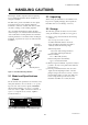
2. HANDLING CAUTIONS 2. HANDLING CAUTIONS This chapter describes important cautions regarding how to handle the transmitter. Read carefully before using the transmitter. The EJA Series pressure transmitters are thoroughly tested at the factory before shipment. When the transmitter is delivered, visually check them to make sure that no damage occurred during shipment. Also check that all transmitter mounting hardware shown in Figure 2.1 is included.
2. HANDLING CAUTIONS 2.4 Selecting the Installation Location The following precautions must be observed in order to safely operate the transmitter under pressure. The transmitter is designed to withstand severe environmental conditions. However, to ensure stable and accurate operation for years, observe the following precautions when selecting an installation location. (a) Never apply a pressure higher than the specified maximum working pressure.
2. HANDLING CAUTIONS 2.8 Insulation Resistance and Dielectric Strength Test 5) After completing this test, slowly decrease the voltage to avoid any voltage surges. Since the transmitter has undergone insulation resistance and dielectric strength tests at the factory before shipment, normally these tests are not required. However, if required, observe the following precautions in the test procedures. 2.
2. HANDLING CAUTIONS • Intrinsically Safe Apparatus Parameters [Groups C, D, E, F and G] Vmax = 30 V Ci = 22.5 nF Imax = 225 mA Li = 730 µH Pmax = 0.9 W * Associated Apparatus Parameters (FM approved barriers) Voc ≤ 30 V Ca > 22.5 nF Isc ≤ 225 mA La > 730 µH Pmax ≤ 0.
2. HANDLING CAUTIONS Note 4. Maintenance and Repair • The instrument modification or parts replacement by other than authorized representative of Yokogawa Electric Corporation is prohibited and will void Factory Mutual Explosionproof Approval. c. FM Intrinsically Safe Type/FM Explosionproof Type Model EJA Series pressure transmitters with optional code /FU1 can be selected the type of protection (FM Intrinsically Safe or FM Explosionproof) for use in hazardous locations. Note 1.
2. HANDLING CAUTIONS Note 2. Wiring • All wiring shall comply with Canadian Electrical Code Part I and Local Electrical Codes. • In hazardous location, wiring shall be in conduit as shown in the figure. CAUTION: SEAL ALL CONDUITS WITHIN 50 cm OF THE ENCLOSURE. UN SCELLEMENT DOIT ÊTRE INSTALLÉ À MOINS DE 50 cm DU BÎTIER. • When installed in Division 2, “SEALS NOT REQUIRED.” Note 3. Operation • Keep the “CAUTION” label attached to the transmitter. CAUTION: OPEN CIRCUIT BEFORE REMOVING COVER.
2. HANDLING CAUTIONS [Intrinsic Safety] Hazardous Location (Zone 0) EJA Series Pressure Transmitter Nonhazardous Location + + Safety Barrier *1 – – F0206.EPS *1: Any safety barriers used for the output current must be limited by a resistor “R” such that Imaxout-Uz/R. [Type n] Hazardous Location (Zone 2) EJA Series Pressure Transmitter + + Power Supply *2 – – F0207.EPS *2: The voltage of the power supply is not exceed 30V dc. b. SAA Flameproof Type Caution for SAA flameproof type. Note 1.
2. HANDLING CAUTIONS b. CENELEC (KEMA) Flameproof Type Caution for CENELEC (KEMA) flameproof type. Note 1. Model EJA Series differential, gauge, and absolute pressure transmitters with optional code /KF1 for potentially explosive atmospheres: • Type of Protection and Marking Code: EEx d IIC T6···T4 • Temperature Class: T6, T5, and T4 • Maximum Process Temperature: 85°C (T6), 100°C (T5), and 120°C • Ambient Temperature: –40 to 80°C Note 2. Electrical Data • Supply voltage: 42 V dc max.
2. HANDLING CAUTIONS 2.9.5 JIS Certification 2.10 EMC Conformity Standards JIS Flameproof and Intrinsically Safe Type For EMI (Emission): EN55011, AS/NZS 2064 1/2 For EMS (Immunity): EN50082–2 The model EJA Series pressure transmitters with optional code /JF1 and /JS1, which have obtained certification according to technical criteria for explosion-protected construction of electric machinery and equipment(Standards Notification No.
3. COMPONENT NAMES 3. COMPONENT NAMES Transmitter section* *See below for details. Cover flange Capillary tube Diaphragm seal (high pressure side) Pressure-detector section Diaphragm Diaphragm seal (low pressure side) Flange F0301.EPS Figure 3.1.
4. INSTALLATION 4. INSTALLATION 4.1 Precautions IMPORTANT j Before installing the transmitter, read the cautionary notes in Section 2.4, “Selecting the Installation Location.” For additional information on the ambient conditions allowed at the installation location, refer to Subsection 9.1 “Standard Specifications.
4. INSTALLATION 4.3 Transmitter Mounting IMPORTANT j The transmitter can be mounted on a nominal 50 mm (2-inch) pipe using the mounting bracket supplied, as shown in Figure 4.3.1. The transmitter can be mounted on either a horizontal or a vertical pipe. j When mounting the bracket on the transmitter, tighten the (four) bolts that hold the transmitter to a torque of approximately 39 N·m {4 kgf·m}.
4. INSTALLATION 4.4 Affixing the Teflon Film 4.5 Rotating Transmitter Section The FEP Teflon option includes a teflon film and fluorinated oil. Before mounting the diaphragm seal to the process flange, affix the teflon film as follows: The DPharp transmitter section can be rotated in 90° segments. IMPORTANT (1) Position the diaphragm seal so that the diaphragm is in a upward position. (2) Pour the fluorinated oil on the diaphragm and gasket area covering it completely and evenly.
5. WIRING 5. WIRING 5.1 Wiring Precautions CAUTION If the transmitter is flameproof and the ambient temperature is 50°C or more, use cables having a maximum allowable heat resistance of at least 75°C in consideration of the instrument's generation of heat or the cables' self-heating. IMPORTANT • Lay wiring as far as possible from electrical noise sources such as large capacity transformers, motors, and power supplies. • Remove electrical connection dust cap before wiring.
5. WIRING 5.3.3 BRAIN TERMINAL BT200 Connection Connect the BT200 to the SUPPLY + and – terminals (Use hooks). Transmitter terminal box + Power supply – Ignore the polarity since the BT200 is AC-coupled to the terminal box. BT200 F0503.EPS 5.4.1 Loop Configuration Since the DPharp uses a two-wire transmission system, signal wiring is also used as power wiring. DC power is required for the transmitter loop. The transmitter and distributor are connected as shown below.
5. WIRING 5.4.2 Wiring Installation (1) General-use Type and Intrinsically Safe Type Make cable wiring using metallic conduit or waterproof glands. • Apply a non-hardening sealant to the terminal box connection port and to the threads on the flexible metal conduit for waterproofing. • Measure the cable outer diameter in two directions to within 1 mm. • Calculate the average of the two diameters, and use packing with an internal diameter nearest to this value (see Table 5.4.2). Table 5.4.
, 5. WIRING j Flameproof metal conduit wiring • A seal fitting must be installed near the terminal box connection port for a sealed construction. • Apply a non-hardening sealant to the threads of the terminal box connection port, flexible metal conduit and seal fitting for waterproofing. 5.6 Power Supply Voltage and Load Resistance When configuring the loop, make sure that the external load resistance is within the range in the figure below.
6. OPERATION 6. OPERATION 6.1 Preparation for Starting Operation The Model EJA118W, EJA118N and EJA118Y diaphragm sealed differential pressure transmitter measures the flow rates of liquids, gases, and steam, liquid levels, and liquid densities. This section describes the operation procedure for the EJA118W as shown in Figure 6.1.1 when measuring liquid level in a closed tank. (a) Confirm that there is no leak in the connecting part of each diaphragm seal mounting flange.
6. OPERATION 6.2 Zero Point Adjustment Adjust the zero point after operating preparation is completed. 6.2.1 When you can obtain Low Range Value from actual measured value of 0% (0 kPa, atmospheric pressure); j IMPORTANT Do not turn off the power to the transmitter immediately after a zero adjustment. Powering off within 30 seconds after a zero adjustment will return the adjustment back to the previous settings.
6. OPERATION j Using the Transmitter Zero-Adjustment Screw Turn the screw to match the output signal to the actual measured value in %. j Using the BT200 Select the parameter J10: ZERO ADJ. Change the set point (%) displayed for the parameter to the actual measured value (%), and press the ENTER key twice. See Subsection 7.3.3 (12) for operation details. A display at J10 SET J10:ZERO ADJ –0.0 % + 000.0 CLR 6.
6. OPERATION 6.5 Setting the Range Using the Range-setting Switch IMPORTANT • Do not turn off the power to the transmitter immediately after completion of the change in the LRV (and/or HRV) setting(s). Note that powering off within thirty seconds after setting will cause a return to the previous settings. • Changing LRV a utomatically changes HRV to the following value.
7. BRAIN TERMINAL BT200 OPERATION 7. BRAIN TERMINAL BT200 OPERATION The DPharp is equipped with BRAIN communications capabilities, so that range changes, Tag No. setup, monitoring of self-diagnostic results, and zero point adjustment can be handled by remote control via BT200 BRAIN TERMINAL or CENTUM CS console. This section describes procedures for setting parameters using the BT200. For details concerning the BT200, see IM 1C0A10-E, “BT200 User’s Manual.” 7.2 BT200 Operating Procedures 7.2.
7. BRAIN TERMINAL BT200 OPERATION 7.2.2 Operating Key Functions Use the function key [F1] CODE to enter symbols. The following symbols will appear in sequence, one at a time, at the cursor each time you press [F1] CODE: (1) Alphanumeric Keys and Shift Keys You can use the alphanumeric keys in conjunction with the shift keys to enter symbols, as well as alphanumeric keys. / . – , + * ) ( ’ & % $ # ” ! To enter characters next to these symbols, press [ > ] to move the cursor.
7. BRAIN TERMINAL BT200 OPERATION 7.2.3 Calling Up Menu Addresses Using the Operating Keys ––WELCOME–– BRAIN TERMINAL ID: BT200 STARTUP SCREEN check connection push ENTER key UTIL The utility screen contains the following items. 1. BT200 ID settings 2. Security code settings 3. Switching language of messages (Japanese or English) 4. LCD contrast setting 5. Adjusting printout tone (BT200-P00 only) UTILITY 1.ID 2.SECURITY CODE 3.LANGUAGE SELECT 4.LCD CONTRAST 5.
7. BRAIN TERMINAL BT200 OPERATION 7.3 Setting Parameters Using the BT200 7.3.1 Parameter Summary Instruments to which applicable: F: Differential pressure transmitters P: Pressure transmitters L: Liquid level transmitters No. Item 01 MODEL 02 TAG NO. EJA110, EJA120, EJA118W, EJA118N, EJA118Y, and EJA115 EJA310, EJA430, EJA438W, and EJA438N EJA210 and EJA220 Description Model+capsule type Tag number 03 SELF CHECK Self-diagnostic result A DISPLAY A10 OUTPUT (%) A11 ENGR.
7. BRAIN TERMINAL BT200 OPERATION No. D Item AUX SET 1 Description Auxiliary setting data 1 Rewritability — D21 DISP UNIT D22 D23 D30 D31 Engineering unit for display DISP LRV Engineering range, lower range value DISP HRV Engineering range, higher range value TEMP UNIT Temperature setting units STAT. P.
7. BRAIN TERMINAL BT200 OPERATION 7.3.2 Parameter Usage and Selection IMPORTANT Before describing the procedure for setting parameters, we present the following table showing how the parameters are used and in what case. If the transmitter is turned off within 30 seconds after parameters have been set, the set data will not be stored and the terminal returns to previous settings. Table 7.3.1 Parameter Usage and Selection Setup Item Tag No. setup c P.7-7 Calibration range setup c P.
7. BRAIN TERMINAL BT200 OPERATION 7.3.3 Setting Parameters Set or change the parameters as necessary. After completing these, do not fail to use the “DIAG” key to confirm that “GOOD” is displayed for the selfdiagnostic result at _60: SELF CHECK. SET C10:TAG NO. YOKOGAWA FIC-1a This is the panel for confirming set data. The set data items flash. PRINTER OFF F2:PRINTER ON FEED POFF NO When all items have been confirmed, press the again. (To go back to the setting panel, press the (1) Tag No.
7. BRAIN TERMINAL BT200 OPERATION b. Setting Calibration Range Lower Range Value and Higher Range Value (C21: LOW RANGE, C22: HIGH RANGE) These range values are set as specified in the order before the instrument is shipped. Follow the procedure below to change the range. • Example 2: With present settings of 0 to 30 kPa, set the Higher range value to10 kPa. DEL FEED CLR NO SET C20:PRESS UNIT kPa C21:LOW RANGE 0.5 kPa C22:HIGH RANGE 30.5 kPa DATA DIAG PRNT key twice ESC Press the (OK) key.
7. BRAIN TERMINAL BT200 OPERATION (4) Output Mode and Integral Indicator Display Mode Setup (C40: OUTPUT MODE) The mode setting for the output signal and the integral indicator coordinate as shown in the table below. BT200 Display Output Mode Integral Indicator Display Mode OUT: LIN DSP: LIN Linear Linear • Example: Change the low cut setting range from 10% to 20%, and the low cut mode from LINEAR to ZERO.
7. BRAIN TERMINAL BT200 OPERATION (6) Integral Indicator Scale Setup The following 5 displays are available for integral indicators. D20: DISP SELECT and Display NORMAL % Description and Related parameters Indicates –5 to 110% range depending on the Measurement range (C21, C22). User-set engineering unit display D20: DISP SELECT NORMAL % INP PRES PRES & % D20: DISP SELECT USER SET USER & % Set for user-set engineering unit display. Transmitter is set A10:OUTPUT (%) 45.
7. BRAIN TERMINAL BT200 OPERATION b. Setting User-set Engineering Unit (D21: DISP UNIT) This parameter allows entry of the engineering units to be displayed on the BT200. When the instrument is shipped, this is set as specified in the order. c. Lower and Higher Range Value Setup in Engineering Unit (D22: DISP LRV, D23: DISP HRV) These parameter items are used to set the lower and higher range values for the engineering unit display. Follow the procedure below to change this setting.
7. BRAIN TERMINAL BT200 OPERATION (8) Unit Setup for Displayed Static Pressure (D31: STAT.P.UNIT) Follow the procedure below to change the static pressure units. Changing this parameter changes the unit for the A30: STATIC PRESS (static pressure) display. (11) Output Status Display/Setup when a CPU Failure (D52: BURN OUT) This parameter displays the status of 4 to 20 mA DC output if a CPU failure occurs. In case of a failure, communication is disabled. Setting of HIGH or LOW is enabled.
7. BRAIN TERMINAL BT200 OPERATION (13) Bi-directional Flow Measurement Setup (E30: BI DIRE MODE) (a) This parameter enables selection of 50% output at an input of 0 kPa. Procedure is shown in the figure below. (b) Combining this with C40: OUTPUT MODE provides a square root output computed independently for 0% to 50% output and for 50% to 100% output.
7. BRAIN TERMINAL BT200 OPERATION Note that changing the higher range value does not cause the lower range value to change but does change the span. (a) Follow the procedure below when setting the present output to 0% (4 mA). Output is 0.5%. A10:OUTPUT (%) 0.5 % • Example 2: When the higher range value is to be changed to 10 kPa with the present setting of 0 to 30 kPa, take the following action with an input pressure of 10 kPa applied. SET J10:ZERO ADJ 0.0 % + 000.
7. BRAIN TERMINAL BT200 OPERATION (16) Test Output Setup (K10: OUTPUT X%) This feature can be used to output a fixed current from 3.2 mA (–5%) to 21.6 mA (110%) for loop checks. (b)-2 Follow the procedure below to use J11: ZERO DEV. Present output is 41.0%. A10:OUTPUT (%) 41.0 % Output error = 45.0 – 41.0 = 4.0%. • Example: Output 12 mA (50%) fixed current. Since “J11: ZERO DEV.” contains SET J11:ZERO DEV. 2.50 % 0 SET K10:OUTPUT X % 0.0 % + 050.0 the previous correction, obtain the Set “50.0%.
7. BRAIN TERMINAL BT200 OPERATION 7.4 Displaying Data Using the BT200 7.4.1 7.5 Self-Diagnostics 7.5.1 Displaying Measured Data Checking for Problems (1) Identifying Problems with BT200 The following four areas can be checked. (a) Whether connections are good. (b) Whether BT200 was properly operated. (c) Whether settings were properly entered. (d) History of the errors. See examples below. The BT200 can be used to display measured data. The measured data is updated automatically every 7 seconds.
7. BRAIN TERMINAL BT200 OPERATION (2) Checking with Integral Indicator • Example 3: Checking the history of the errors Connect the BT200 to the MENU J:ADJUST K:TEST M:MEMO P:RECORD HOME SET NOTE transmitter, and call item “P.” ADJ ESC PARAM P10:ERROR REC 1 ERROR P11:ERROR REC 2 ERROR P12:ERROR REC 3 GOOD DATA DIAG PRNT ESC If an error is detected in the self-diagnostic, an error number is displayed on the integral indicator.
7. BRAIN TERMINAL BT200 OPERATION 7.5.2 Errors and Countermeasures The table below shows a summary of error messages. Table 7.5.1 Error Message Summary Integral Indicator Display BT200 Display Output Operation during Error Cause Countermeasure None GOOD ---- ERROR Er. 01 CAP MODULE FAULT Capsule problem. Outputs the signal (Hold, High, or Low) set with parameter D53. Replace capsule. Er. 02 AMP MODULE FAULT Amplifier problem.
8. MAINTENANCE 8. MAINTENANCE 8.1 Overview WARNING Since the accumulated process fluid may be toxic or otherwise harmful, take appropriate care to avoid contact with the body, or inhalation of vapors during draining condensate or venting gas in transmitter pressure-detector section even after dismounting the instrument from process line for maintenance. Maintenance of the transmitter is easy due to its modular construction.
8. MAINTENANCE Table 8.2.1 Tools for Disassembly and Reassembly Name Power supply Load resistor Voltmeter Yokogawa-recommended Instrument 4 to 20 mA DC signal Model SDBT or SDBS distributor Model 2792 standard resistor [250 Ω ±0.005%, 3 W] Load adjustment resistor [100 Ω ±1%, 1 W] Model 2501 A digital multimeter Accuracy (10V DC range): ±(0.002% of rdg + 1 dgt) Model MT110, MT120 precision digital manometer 1) For 10 kPa class Accuracy: ±(0.015% of rdg + 0.015% of F.S.) . . . . . ±(0.2% of rdg + 0.
8. MAINTENANCE 8.4 Disassembly and Reassembly This section describes procedures for disassembly and reassembly for maintenance and component replacement. 8.4.1 Replacing the Integral Indicator This subsection describes the procedure for replacing an integral indicator. (See Figure 8.4.2) CAUTION Always turn OFF power and shut off and release pressures before disassembly. Use proper tools for all operations. Table 8.4.1 shows the tools required.
8. MAINTENANCE 8.4.2 Replacing the CPU Assembly NOTE This subsection describes the procedure for replacing the CPU assembly. (See Figure 8.4.2) j Removing the CPU Assembly 1) Remove the cover. If an integral indicator is mounted, refer to Subsection 8.4.1 and remove the indicator. 2) Turn the zero-adjustment screw to the position (where the screw head slot is horizontal) shown in Figure 8.4.2. 3) Disconnect the output terminal cable (cable with brown connector at the end).
8. MAINTENANCE 8.5 Troubleshooting 8.5.2 Troubleshooting Flow Charts If any abnormality appears in the measured values, use the troubleshooting flow chart below to isolate and remedy the problem. Since some problems have complex causes, these flow charts may not identify all. If you have difficulty isolating or correcting a problem, contact Yokogawa service personnel. The following sorts of symptoms indicate that transmitter may not be operating properly. Example : • There is no output signal.
8. MAINTENANCE Output travels beyond 0% or 100%. Large output error. Connect BRAIN TERMINAL and check self-diagnostics. Connect BRAIN TERMINAL and check self-diagnostics. Does the selfdiagnostic indicate problem location? NO Refer to error message summary in Subsection 7.5.2 to take actions. Are high and low pressure side diaphragm seals correctly connected to the process? YES Does the selfdiagnostic indicate the problem location? YES NO Refer to error message summary in Subsection 7.5.
9. GENERAL SPECIFICATIONS 9. GENERAL SPECIFICATIONS 9.1 Standard Specifications Ambient Temperature Limits: * Safety approval codes may affect limits. –40 to 60°C (–40 to 140°F) –30 to 60°C (–22 to 140°F) with LCD Display Refer to GS 1C22T2-E for Fieldbus communication type marked with “e”. d Performance Specifications Note: The ambient temperature limits must be within the fill fluid operating temperature range, see Table 1. See General Specifications sheet, GS 1C22H1-E.
9. GENERAL SPECIFICATIONS Process temperature Process temperature Process temperature for fill fluid code B for fill fluid code A for fill fluid code C Transmitter ambient temperature range (For fill fluid code A,B) Flange max. working pressure d Physical Specifications Wetted Parts Materials: Diaphragm and other wetted parts; See ‘Model and Suffix Codes’ Non-wetted Parts Materials: Capillary tube; SUS316 Atmospheric 100{750} Protection tube; pressure SUS304, PVC-sheathed [Max.
9. GENERAL SPECIFICATIONS 9.2 Model and Suffix Codes d Model EJA118W Model [Style: S2] Suffix Codes Description . . . . . . . . . . . . . . . . . . . . . . . . . . . . . . . . . . Diaphragm sealed differential pressure transmitter EJA118W (Flush diaphragm type) Output Signal -D . . . . . . . . . . . . . . . . . . . . . . . . . . . . . . . . 4 to 20 mA DC with digital communication (BRAIN protocol) -E . . . . . . . . . . . . . . . . . . . . . . . . . . . . . . . .
9. GENERAL SPECIFICATIONS d Model EJA118N [Style: S2] Model Suffix Codes Description . . . . . . . . . . . . . . . . . . . . . . . . . . . . . . . . . . Diaphragm sealed differential pressure transmitter EJA118N (Extended diaphragm type) -D . . . . . . . . . . . . . . . . . . . . . . . . . . . . . . . . 4 to 20 mA DC with digital communication (BRAIN protocol) Output Signal -E . . . . . . . . . . . . . . . . . . . . . . . . . . . . . . . .
9. GENERAL SPECIFICATIONS d Model EJA118Y Model EJA118Y Output Signal [Style: S2] Suffix Codes Description . . . . . . . . . . . . . . . . . . . . . . . . . . . . . . . . . . . Diaphragm sealed differential pressure transmitter (Combination of extended diaphragm and flush diaphragm type) -D . . . . . . . . . . . . . . . . . . . . . . . . . . . . . . . . 4 to 20 mA DC with digital communication (BRAIN protocol) -E . . . . . . . . . . . . . . . . . . . . . . . . . . . . . . . .
9. GENERAL SPECIFICATIONS 9.3 Optional Specifications Item Factory Mutual (FM) Description FM Explosionproof Approval Explosionproof for Class I, Division 1, Groups B, C and D Dust-ignitionproof for Class II/III, Division 1, Groups E, F and G Hazardous (classified) locations, indoors and outdoors ( NEMA 4X ) Temperature class: T6 Amb. Temp.
9. GENERAL SPECIFICATIONS Item Description Code Color change Amplifier cover only Ph Coating change Epoxy resin-baked coating X1 Lightning protector Transmitter power supply voltage: 10.5 to 32 V DC (9 to 32 V DC for Fieldbus communication type) Allowable current: Max.
9. GENERAL SPECIFICATIONS 9.4 Dimensions d Model EJA118W [Style: S2] Unit: mm (approx.inch) 25 (0.98) t f 34 (1.34) øg øC øD ød*1 n- øh Wetted parts material code U (Titanium) External indicator conduit connection High pressure side 94(3.70) 9 (0.35) Conduit connection (Optional) ø78 (3.07) Internal indicator 47 (1.85) 124 (4.88) 197(7.76) (Optional) 333(13.11) Low pressure side 110 (4.
9. GENERAL SPECIFICATIONS d Model EJA118N [Style: S2] Unit : mm (approx.inch) øD øC øg 120 (4.72) X2 ø30 (1.18) f n-øh Low pressure side 140(5.51) External indicator conduit connection (Optional) 110 (4.33) 94(3.70) 9 (0.35) Conduit connection ø78 (3.07) Internal indicator Terminal side 124 (4.88) Zero adjustment Ground terminal Clamps (Only for JIS Flameproof type) 92 (3.62) 47 (1.85) 333(13.11) 197(7.76) (Optional) 2-inch pipe (O.D. 60.5mm) 146(5.75) t 14(0.
9. GENERAL SPECIFICATIONS d Model EJA118Y [Style: S2] Unit: mm (approx.inch) 25 (0.98) øD øC t f ø90*1 (3.54) ø155 (6.10) ø96 (3.78) 14 (0.55) ø30 (1.18) 120 (4.72) n-φh Low pressure side 110 (4.33) 15 (0.59) 53 (2.09) Conduit connection External indicator conduit connection (Optional) øC øD n-φh f High pressure side 135 (5.31) ø130 (5.12) t X2 ø78 (3.07) Terminal side Internal indicator (Optional) 334 (13.15) 124 (4.88) Ground terminal Zero adjustment 47 (1.85) 48 (1.
INSTALLATION AND OPERATING PRECAUTIONS FOR JIS INTRINSICALLY SAFE EQUIPMENT INSTALLATION AND OPERATING PRECAUTIONS FOR JIS INTRINSICALLY SAFE EQUIPMENT Apparatus Certified Under Technical Criteria (IEC-compatible Standards) and from “RECOMMENDED PRACTICES for Explosion-Protected Electrical Installations in General Industries,” published in 1979 1.
INSTALLATION AND OPERATING PRECAUTIONS FOR JIS INTRINSICALLY SAFE EQUIPMENT (2) For pressure transmitters, pH transmitters, temperature detectors and the like, safety barriers that can be combined are already specified. Other safety barriers cannot be used. — when up to two countable faults are applied and, in addition, — when non-countable faults produce an onerous condition.
INSTALLATION AND OPERATING PRECAUTIONS FOR JIS INTRINSICALLY SAFE EQUIPMENT intrinsically safe apparatus may be used at an ambient temperature up to 60°C. So, specifications should be checked before installing intrinsically safe apparatus. Installations for Explosive Gas Atmospheres in General Industry” issued in 1994 by the Japanese Ministry of Labour, the Research Institute of Industrial Safety.
INSTALLATION AND OPERATING PRECAUTIONS FOR JIS FLAMEPROOF EQUIPMENT INSTALLATION AND OPERATING PRECAUTIONS FOR JIS FLAMEPROOF EQUIPMENT Apparatus Certified Under Technical Criteria (IEC-compatible Standards) 1. General construction is of completely enclosed type and its enclosure shall endure explosive pressures in cases where explosive gases or vapours entering the enclosure cause explosion.
INSTALLATION AND OPERATING PRECAUTIONS FOR JIS FLAMEPROOF EQUIPMENT 4. Installation of Flameproof Apparatus • Specific cables shall be used as recommended by the “USER’S GUIDELINES for Electrical Installations for Explosive Gas Atmospheres in General Industry,” published in 1994. • In necessary, appropriate protective pipes (conduit or flexible pipes), ducts or trays shall be used for preventing the cable run (outside the cable glands) from damage.
INSTALLATION AND OPERATING PRECAUTIONS FOR JIS FLAMEPROOF EQUIPMENT 6. Maintenance of Flameproof Apparatus requirements for flameproof apparatus (however, bear in mind that the apparatus must always be restored to its original condition). If you attempt to repair the flameproof apparatus, company-specified components shall be used. (d) Before starting to service the apparatus, be sure to check all parts necessary for retaining the requirements for flameproof apparatus.
Blank Page
Customer Maintenance Parts List DPharp EJA Series Transmitter Section 2 5 4 11 A 10 3 12 13 1 2 2 1 14 A 6 7-1 Item Part No.
2 Blank Page Subject to change without notice. Printed in Japan.
Customer Maintenance Parts List Models EJA118W, EJA118N and EJA118Y Diaphragm Sealed Differential Pressure Transmitter (Pressure-detector Section) Model EJA118W Model EJA118N Model EJA118Y All Rights Reserved, Copyright © 1995, Yokogawa Electric Corporation. CMPL 1C22H1-01E 3rd Edition: Oct.
2 5 6 7 8 9 F9300AJ — — Below Y9625YU Y9630YU Y9640YU Y9635YU Y9612HU Below F9270AW F9300TA D0117XL-A Below F9270AX F9300TE Below F9270AY F9273CZ EJA118Y 1 2 3 4 EJA118N Model Item Part No.
REVISION RECORD Title: Model EJA118W, EJA118N, and EJA118Y Diaphragm Sealed Differential Pressure Transmitter Manual No.: IM 1C22H1-01E Edition Date Page 8th Mar. 1998 1-1 4-5 5-1 10-1 10-3 10-7 2-9+ CMPL 9th Sep. 1998 2-14 2-15 7-20 10-3 10-4 10-5 CMPL 10th Feb. 2000 – 2-9 Revised Item 1 4.4 • Add FOUNDATION Fieldbus protcol version to ‘NOTE’ notice. • Correct Teflon film Part Number. F9347YD (Incorrect) F9347YA (Correct) 5.1 • Add Item 6 to the Wiring Precautions. 10.1.
Edition Date Page – 9-7 CMPL Revised Item – • Installation and Operating Precautions for JIS Intrinsically Safe and Explosionproof Equipment: EX-A01E EX-A03E, EX-B01E EX-B03E 9-3 • Add Optional code F1. CMPL 1C22A1-02E 5th 6th • Change a format. • Change and add Part No. of Item 7-1, CPU assembly: Change; F9342BC F9342BB, F9342BK F9342BJ Add; F9342AF, F9342AM • Change Part No. of Item 10, Plug: G9330DK G9330DP CMPL 1C22H1-01E 3rd • Change a format REVISION RECORD.