User’s Manual Differential Pressure and Pressure Transmitters EJ110, EJ120, EJ130, EJ310, EJ430, and EJ440 IM 01C25B01-01E IM 01C25B01-01E 13th Edition
i Differential Pressure and Pressure Transmitters EJ110, EJ120, EJ130, EJ310, EJ430, and EJ440 IM 01C25B01-01E 13th Edition Contents 1. Introduction................................................................................................ 1-1 Regarding This Manual................................................................................................. 1-1 2. 1.1 Safe Use of This Product .................................................................................
ii 5. Installing Impulse Piping.......................................................................... 5-1 5.1 5.2 6. Connecting Impulse Piping to a Transmitter....................................... 5-1 5.1.2 Routing the Impulse Piping................................................................. 5-3 Impulse Piping Connection Examples............................................................ 5-4 6.1 Wiring Precautions.........................................................................
iii 8.5 9. Troubleshooting................................................................................................. 8-6 8.5.1 Basic Troubleshooting........................................................................ 8-6 8.5.2 Troubleshooting Flowcharts................................................................ 8-7 8.5.3 Alarms and Countermeasures............................................................ 8-9 General Specifications....................................................
1. 1-1 <1. Introduction> Introduction Thank you for purchasing the DPharp Differential Pressure and pressure transmitter. Your transmitter was precisely calibrated at the factory before shipment. To ensure both safety and efficiency, please read this manual carefully before you operate the instrument. NOTE This manual describes the hardware configurations of the transmitters listed in below.
• Yokogawa assumes no responsibilities for this product except as stated in the warranty. • If the customer or any third party is harmed by the use of this product, Yokogawa assumes no responsibility for any such harm owing to any defects in the product which were not predictable, or for any indirect damages. • The following safety symbols are used in this manual: 1-2 <1. Introduction> 1.
(c) Operation • Wait 5 min. after the power is turned off, before opening the covers. (d) Maintenance • Please carry out only the maintenance procedures described in this manual. If you require further assistance, please contact the nearest Yokogawa office. • Care should be taken to prevent the build up of dust or other materials on the display glass and the name plate. To clean these surfaces, use a soft, dry cloth.
1.3 <1. Introduction> 1-4 ATEX Documentation This is only applicable to the countries in European Union.
2. 2-1 <2. Handling Cautions> Handling Cautions This chapter provides important information on how to handle the transmitter. Read this carefully before using the transmitter. The transmitters are thoroughly tested at the factory before shipment. When taking delivery of an instrument, visually check them to make sure that no damage occurred during shipment. Also check that all transmitter mounting hardware shown in figure 2.1 is included.
2.4 Selecting the Installation Location The transmitter is designed to withstand severe environmental conditions. However, to ensure that it will provide years of stable and accurate performance, take the following precautions when selecting the installation location. (a) Ambient Temperature Avoid locations subject to wide temperature variations or a significant temperature gradient.
<2. Handling Cautions> 2-3 (b) Never apply a voltage exceeding 500 V DC (100 V DC with an internal lightning protector) for the insulation resistance test, nor a voltage exceeding 500 V AC (100 V AC with an internal lightning protector) for the dielectric strength test. (c) Before conducting these tests, disconnect all signal lines from the transmitter terminals. The procedure for conducting these tests is as follows: 2.
IMPORTANT For combined approval types Once a device of multiple approval type is installed, it should not be re-installed using any other approval types. Apply a permanent mark in the check box of the selected approval type on the certification label on the transmitter to distinguish it from unused approval types. IMPORTANT All the blind plugs which accompany the EJX/ EJA-E transmitters upon shipment from the factory are certified by the applicable agency in combination with those transmitters.
<2. Handling Cautions> Note 4. Maintenance and Repair • The instrument modification or parts replacement by other than authorized representative of Yokogawa Electric Corporation is prohibited and will void Factory Mutual Intrinsically safe and Nonincendive Approval. Note 2. Wiring • All wiring shall comply with National Electrical Code ANSI/NFPA70 and Local Electrical Codes. • When installed in Division 1, “FACTORY SEALED, CONDUIT SEAL NOT REQUIRED.
2.9.2 CSA Certification a. CSA Intrinsically Safe Type Caution for CSA Intrinsically safe and nonincendive type. (Following contents refer to “DOC No. ICS013-A13”) Note 1. Model EJX/EJA-E Series differential, gauge, and absolute pressure transmitters with optional code /CS1 are applicable for use in hazardous locations Certificate: 1606623 [For CSA C22.2] • Applicable Standard: C22.2 No.0, C22.2 No.0.4, C22.2 No.25, C22.2 No.94, C22.2 No.157, C22.2 No.213, C22.2 No.61010-1, C22.2 No.
<2. Handling Cautions> • Explosion-proof for Class I, Groups B, C and D. • Dustignition-proof for Class II/III, Groups E, F and G. • Enclosure: NEMA TYPE 4X • Temperature Code: T6...T4 • Ex d IIC T6...T4 • Enclosure: IP66/IP67 • Maximum Process Temperature: 120°C (T4), 100°C (T5), 85°C (T6) • Ambient Temperature: –50* to 75°C (T4), –50* to 80°C (T5), –50* to 75°C (T6) * –15°C when /HE is specified. • Supply Voltage: 42 V dc max. • Output Signal: 4 to 20 mA dc Note 2.
2.9.3 ATEX Certification (1) Technical Data a. ATEX Intrinsically Safe Ex ia Caution for ATEX Intrinsically safe type. Note 1. Model EJX/EJA-E Series pressure transmitters with optional code /KS21 for potentially explosive atmospheres: • No.
b. ATEX Flameproof Type WARNING Caution for ATEX flameproof type. Note 1. Model EJX/EJA-E Series pressure transmitters with optional code /KF22 for potentially explosive atmospheres: • No. KEMA 07ATEX0109 X • Applicable Standard: EN 60079-0:2009, EN 60079-1:2007, EN 60079-31:2009 • Type of Protection and Marking Code: Ex d IIC T6...
● ATEX Intrinsically Safe Ex ic WARNING Caution for ATEX intrinsically safe Ex ic • Applicable Standard: EN 60079-0:2009/EN 60079-0:2012, EN 60079-11:2012 • Type of Protection and Marking Code: II 3G Ex ic IIC T4 Gc • Ambient Temperature: –30* to +60°C * –15°C when /HE is specified. • Ambient Humidity: 0 to 100% (No condensation) • Maximum Process Temperature: 120°C • IP Code: IP66 • Ambient pollution degree: 2 • Overvoltage category: I Note 1. Electrical Data Ui = 30 V Ci = 27.
2-11 <2. Handling Cautions> (5) Maintenance and Repair *1: The first digit in the three numbers next to the nine letters of the serial number appearing after “NO.” on the nameplate indicates the year of production. The following is an example of a serial number for a product that was produced in 2010: WARNING 91K819857 The instrument modification or parts replacement by other than an authorized Representative of Yokogawa Electric Corporation is prohibited and will void the certification.
<2. Handling Cautions> • Installation Requirements Uo ≤ Ui, Io ≤ Ii, Po ≤ Pi, Co ≥ Ci + Ccable, Lo ≥ Li + Lcable Voc ≤ Vmax, Isc ≤ Imax, Ca ≥ Ci + Ccable, La ≥ Li + Lcable Uo, Io, Po, Co, Lo, Voc, Isc, Ca and La are parameters of barrier. Note 3. Installation • In any safety barrier used output current must be limited by a resistor 'R' such that Io=Uo/R. • The safety barrier must be IECEx certified. • Input voltage of the safety barrier must be less than 250 Vrms/Vdc.
2-13 <2. Handling Cautions> 2.11 Pressure Equipment Directive (PED) *1: *2: (1) General • EJX/EJA-E Series pressure transmitters are categorized as piping under the pressure accessories section of directive 97/23/EC, which corresponds to Article 3, Paragraph 3 of PED, denoted as Sound Engineering Practice (SEP).
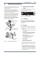
3-1 <3. Component Names> 3. Component Names Vertical impulse piping type Pressure-detector section Terminal box cover Cover flange Horizontal impulse piping type External indicator conduit connection (Note 1) Conduit connection Zeroadjustment screw (Note 2) Slide switch Integral indicator (Note 1) Mounting screw Vent plug CPU assembly Amplifier Cover Drain plug Burnout direction switch Range-setting switch (Note 1) (See section 7.
4. 4.1 Installation Precautions Before installing the transmitter, read the cautionary notes in section 2.4, “Selecting the Installation Location.” For additional information on the ambient conditions allowed at the installation location, refer to subsection 9.1 “Standard Specifications.” 57 mm • When welding piping during construction, take care not to allow welding currents to flow through the transmitter. • Do not step on this instrument after installation.
4.3 Vertical pipe mounting (Process connector downside) Transmitter mounting bolt Mounting bracket 50 mm(2-inch) pipe U-bolt nut U-bolt Vertical pipe mounting (Process connector upside) Changing the Process Connection The transmitter is shipped with the process connection specified at the time of ordering. To change the process connection, the drain (vent) plug must be repositioned. To reposition a drain (vent) plug, use a wrench to slowly and gently unscrew it.
4.4 4-3 <4. Installation> Swapping the High/Lowpressure Side Connection IMPORTANT This section is applicable only for EJ110, EJ120, and EJ130 differential transmitters, and not applicable for gauge or absolute pressure transmitters. 4.4.1 Rotating Pressure-detector Section 180° This procedure can be applied only to a transmitter with a vertical impulse piping type. 4.4.2 Using the Communicator This method is applicable only to the Model EJ110, EJ120, and EJ130.
4.5 4-4 <4. Installation> Rotating Transmitter Section The transmitter section can be rotated approximately 360° (180° to either direction or 360° to one direction from the original position at shipment, depending on the configuration of the instrument.) It can be fixed at any angle within above range. 1) Remove the two setscrews that fasten the transmitter section and capsule assembly, using the Allen wrench. 2) Rotate the transmitter section slowly and stop it at designated position.
5. 5.1 5-1 <5. Installing Impulse Piping> Installing Impulse Piping Impulse Piping Installation Precautions (2) Changing the Process Connector Piping Connections (Figure 4.1) (for differential pressure transmitters) The impulse piping that connects the process outputs to the transmitter must convey the process pressure accurately. If, for example, gas collects in a liquid-filled impulse line, or the drain for a gas-filled impulse line becomes plugged, it will not convey the pressure accurately.
5-2 <5. Installing Impulse Piping> Pipe-Mounting Type 3-Valve Manifold (Figure 5.2) Direct-Mounting Type 3-Valve Manifold (Figure 5.3) 1) Screw nipples into the connection ports on the transmitter side of the 3-valve manifold, and into the impulse piping connecting ports on the process connectors. (To maintain proper sealing, wind sealing tape around the nipple threads.) 2) Mount the 3-valve manifold on the 50 mm (2inch) pipe by fastening a U-bolt to its mounting bracket.
5.1.2 Routing the Impulse Piping (3) Impulse Piping Slope (1) Process Pressure Tap Angles If condensate, gas, sediment or other extraneous material in the process piping gets into the impulse piping, pressure measurement errors may result. To prevent such problems, the process pressure taps must be angled as shown in figure 5.4 according to the kind of fluid being measured. NOTE • If the process fluid is a gas, the taps must be vertical or within 45° either side of vertical.
(7) Preventing Freezing If there is any risk that the process fluid in the impulse piping or transmitter could freeze, use a steam jacket or heater to maintain the temperature of the fluid. NOTE After completing the connections, close the valves on the process pressure taps (main valves), the valves at the transmitter (stop valves), and the impulse piping drain valves, so that condensate, sediment, dust and other extraneous material cannot enter the impulse piping. 5.
6-1 <6. Wiring> 6.1 Wiring Precautions 6.3 IMPORTANT • Lay wiring as far as possible from electrical noise sources such as large capacity transformers, motors, and power supplies. • Remove the electrical connection dust cap before wiring. • All threaded parts must be treated with waterproofing sealant. (A non-hardening silicone group sealant is recommended.) • To prevent noise pickup, do not pass signal and power cables through the same ducts.
6-2 <6. Wiring> 6.3.4 Check Meter Connection (1) General-use Type and Flameproof Type Available only when /AL is not specified. Hazardous Location Connect the check meter to the CHECK + and – terminals. (Use hooks.) Transmitter terminal box Distributor (Power supply unit) PULSE • A 4 to 20 mA DC output signal from the CHECK + and – terminals. Nonhazardous Location SUPP LY CHECKM ALAR Receiver instrument (Note) Use a check meter whose internal resistance is 10 Ω or less.
6-3 <6. Wiring> (2) Flameproof Type 6.5 Wire cables through a flameproof packing adapter, or use a flameproof metal conduit. Grounding is always required for the proper operation of transmitters. Follow the domestic electrical requirements as regulated in each country. For a transmitter with a built-in lightning protector, grounding should satisfy ground resistance of 10Ω or less. ■ Wiring cable through flameproof packing adapter.
7-1 <7. Operation> 7. Operation 7.1 Preparation for Starting Operation This section describes the operation procedure for the EJ110, EJ120 and EJ130 as shown in figure 7.1a (vertical impulse piping type, highpressure connection: right side) when measuring the liquid flow rate, and EJ430, EJ440 and EJ310 as shown in figure 7.1b when measuring pressure.
7-2 <7. Operation> NOTE Vent plug (Fill plug) If any of the above errors are indicated on the display of the integral indicator or the communicator, refer to subsection 8.5.3 for the corrective action. Tap valve Stop valve ■ Verify and Change Transmitter Parameter Setting and Values Drain valve F0702.ai Figure 7.1b Liquid Pressure Measurement ■ Confirming that Transmitter is Operating Properly Using the BT200 • If the wiring system is faulty, ‘communication error’ appears on the display.
<7. Operation> 7.2.1 Adjusting Zero Point for Differential Pressure Transmitters Before adjusting zero point, make sure that the equalizing valve is open. Zero-adjustment screw cover F0705.ai Figure 7.4 External Zero Adjustment Screw The zero-adjustment screw is located inside the cover. Use a slotted screwdriver to turn the zeroadjustment screw. Equalize the transmitter, then turn the screw clockwise to increase the output or counterclockwise to decrease the output.
IMPORTANT • Remove the communicator from the terminal box, and confirm that none of the terminal screws are loose. • Close the terminal box cover and the amplifier cover. Screw each cover in tightly until it will not turn further. • There are two covers that must be locked on the ATEX Flameproof type transmitters. An Allen head bolt (shrouding bolt) under the edge of each cover is used to lock the cover.
<7. Operation> 7.5.2 Venting Gas [Example] 1) Gradually open the vent screw to vent gas from the transmitter pressure-detector section. (See figure 7.6.) 2) When the transmitter is completely vented, close the vent screw. 3) Tighten the vent screw to a torque of 10 N·m. Rerange LRV to 0 and URV to 3 MPa. Vent screw Vent screw When you loosen the vent screw, the gas escpes in the direction of the arrow. Figure 7.6 7.6 F0707.
<7. Operation> 7-6 IMPORTANT • Do not turn off the power to the transmitter immediately after completion of the change in the LRV and/or URV setting(s). Note that powering off within thirty seconds after setting will cause a return to the previous settings. • Changing LRV automatically changes URV to the following value.
8. 8.1 Maintenance Overview 8.3 WARNING Use the procedure below to check instrument operation and accuracy during periodic maintenance or troubleshooting. Since the accumulated process fluid may be toxic or otherwise harmful, take appropriate care to avoid contact with the body or inhalation of vapors when draining condensate or venting gas from the transmitter pressure-detector section and even after dismounting the instrument from the process line for maintenance.
Table 8.1 Name Power supply Load resistor Voltmeter Digital manometer Pressure generator Pressure source 8-2 <8. Maintenance> Instruments Required for Calibration Yokogawa-recommended Instrument Model SDBT or SDBS distributor Model 2792 standard resistor [250 Ω ±0.005%, 3 W] Load adjustment resistor [100 Ω ±1%, 1 W] Model 2501 A digital multimeter Accuracy (10V DC range): ±(0.002% of rdg + 1 dgt) Model MT220 precision digital manometer 1) For 10 kPa class Accuracy: ±(0.015% of rdg + 0.015% of F.S.) .
8.4 Disassembly and Reassembly 8.4.1 Replacing the Integral Indicator This section describes procedures for disassembly and reassembly for maintenance and component replacement. Always turn OFF power and shut off and release pressures before disassembly. Use proper tools for all operations. Table 8.2 shows the tools required. Table 8.2 8-3 <8.
8.4.2 Replacing the CPU Board Assembly This subsection describes the procedure for replacing the CPU assembly. (See figure 8.3) ■ Removing the CPU Assembly 1) Remove the cover. If an integral indicator is mounted, refer to subsection 8.4.1 and remove the indicator. 2) Turn the zero-adjustment screw to the position (where the screw head slot is horizontal) as shown in figure 8.3. 3) Disconnect the output terminal cable (cable with brown connector at the end).
8-5 <8. Maintenance> ■ Removing the Capsule Assembly IMPORTANT Exercise care as follows when cleaning the capsule assembly. • Handle the capsule assembly with care, and be especially careful not to damage or distort the diaphragms that contact the process fluid. • Do not use a chlorinated or acidic solution for cleaning. • Rinse thoroughly with clean water after cleaning. 1) Remove the CPU assembly as shown in subsection 8.4.2.
8.4.4 Replacing the Process Connector Gaskets This subsection describes process connector gasket replacement. (See figure 8.5.) (a) Loosen the two bolts, and remove the process connectors. (b) Replace the process connector gaskets. (c) Remount the process connectors. Tighten the bolts securely and uniformly to a torque shown below, and verify that there are no pressure leaks. Model 8-6 <8.
8-7 <8. Maintenance> 8.5.2 Troubleshooting Flowcharts Output travels beyond 0% or 100%. The following sorts of symptoms indicate that transmitter may not be operating properly. Example : • There is no output signal. • Output signal does not change even though process variable is known to be varying. • Output value is inconsistent with value inferred for process variable. Connect a communicator and check self-diagnostics.
<8. Maintenance> 8-8 Large output error. Connect a communicator and check self-diagnostics. Does the selfdiagnostic indicate problem location? NO Refer to error message summary in each communication manual to take actions. NO Are valves opened or closed correctly? YES Fully close equalizing valve, and fully open high pressure and low pressure valves.
8-9 <8. Maintenance> 8.5.3 Alarms and Countermeasures Table 8.3 Indicator None AL. 01 CAP. ERR AL. 02 AMP. ERR AL. 10 PRESS AL. 11 ST. PRSS AL. 12 CAP. TMP AL. 13 AMP. TMP AL. 30 RANGE AL. 31 SP. RNG AL. 35 *1 P. HI AL. 36 *1 P. LO AL. 37 *1 SP. HI AL. 38 *1 SP. LO AL. 39 *1 TMP. HI AL. 40 *1 TMP. LO AL. 50 P. LRV AL. 51 P. URV AL. 52 P. SPN AL. 53 P. ADJ AL. 54 SP. RNG AL. 55 SP. ADJ AL. 60 SC. CFG AL. 79 OV. DISP Alarm Message Summary Cause Sensor problem. Capsule temperature sensor problem.
9. 9.1 General Specifications Standard Specifications Refer to IM 01C25T02-01E for FOUNDATION Fieldbus communication type and IM 01C25T0401EN for PROFIBUS PA communication type for the items marked with “◊”. EJX310A Measurement Span/Range L M Performance Specifications See General Specifications sheet of each model. Functional Specifications L* M kPa inH2O(/D1) mbar(/D3) mmH2O(/D4) Span 0.1 to 5 0.4 to 20 1 to 50 10 to 500 Range -5 to 5 -20 to 20 -50 to 50 -500 to 500 Span 0.
EJA120E Measurement Span/Range E kPa inH2O(/D1) Span 0.1 to 1 0.4 to 4 1 to 10 10 to 100 Range -1 to 1 -4 to 4 -10 to 10 -100 to 100 mbar(/D3) mmH2O(/D4) EJA130E Measurement Span/Range M H Span kPa 1 to 100 inH2O(/D1) 4 to 400 Range -100 to 100 -400 to 400 Span 20 to 2000 5 to 500 mbar(/D3) mmH2O(/D4) 10 to 1000 100 to 10000 -1000 to 1000 -10000 to 10000 50 to 5000 0.
Normal Operating Condition (Selected features may affect limits.
Maximum Over Pressure EJ310 Capsule L, M A B Supply Voltage 10.5 to 42 V DC for general use and flameproof type. 10.5 to 32 V DC for lightning protector (Option code /A). 10.5 to 30 V DC for intrinsically safe, type n or non-incendive type. Minimum voltage limited at 16.
Physical Specifications Wetted Parts Materials Diaphragm, Cover Flange, Process Connector, Capsule Gasket, and Vent/Drain Plug Refer to “Model and Suffix Code.
9.2 9-6 <9. General Specifications> Model and Suffix Codes Model EJX110A Model EJX110A Output signal Suffix Codes ...................... -D . . . . . . . . . . . . . . . . . . . . . -E . . . . . . . . . . . . . . . . . . . . . -J . . . . . . . . . . . . . . . . . . . . . -F . . . . . . . . . . . . . . . . . . . . . M . . . . . . . . . . . . . . . . . . . H . . . . . . . . . . . . . . . . . . . V . . . . . . . . . . . . . . . . . . . . . . . . . . . . . . . . . . . .
9-7 <9. General Specifications> Model EJX120A Model EJX120A Output signal Suffix Codes ...................... -D . . . . . . . . . . . . . . . . . . . . . -E . . . . . . . . . . . . . . . . . . . . . -J . . . . . . . . . . . . . . . . . . . . . -F . . . . . . . . . . . . . . . . . . . . . -G . . . . . . . . . . . . . . . . . . . . Measurement E . . . . . . . . . . . . . . . . . . . span (capsule) S . . . . . . . . . . . . . . . . . Wetted parts material *1 0 . . . . . . . . . . . . . . .
9-8 <9. General Specifications> Model EJX130A Model EJX130A Output signal Suffix Codes ...................... -D . . . . . . . . . . . . . . . . . . . . . -E . . . . . . . . . . . . . . . . . . . . . -J . . . . . . . . . . . . . . . . . . . . . -F . . . . . . . . . . . . . . . . . . . . . -G . . . . . . . . . . . . . . . . . . . . Measurement M . . . . . . . . . . . . . . . . . . . span (capsule) H . . . . . . . . . . . . . . . . . . . S . . . . . . . . . . . . . . . . .
9-9 <9. General Specifications> Model EJX310A Model EJX310A Output signal Suffix Codes ...................... -D . . . . . . . . . . . . . . . . . . . . . -E . . . . . . . . . . . . . . . . . . . . . -J . . . . . . . . . . . . . . . . . . . . . -F . . . . . . . . . . . . . . . . . . . . . -G . . . . . . . . . . . . . . . . . . . . Measurement L . . . . . . . . . . . . . . . . . . . span (capsule) M . . . . . . . . . . . . . . . . . . . A . . . . . . . . . . . . . . . . . . . B . . . . . . . . . .
9-10 <9. General Specifications> Model EJX430A Model EJX430A Output signal Suffix Codes ...................... -D . . . . . . . . . . . . . . . . . . . . . -E . . . . . . . . . . . . . . . . . . . . . -J . . . . . . . . . . . . . . . . . . . . . -F . . . . . . . . . . . . . . . . . . . . . -G . . . . . . . . . . . . . . . . . . . . Measurement H . . . . . . . . . . . . . . . . . . . span (capsule) A . . . . . . . . . . . . . . . . . . . B . . . . . . . . . . . . . . . . . . .
9-11 <9. General Specifications> Model EJX440A Model EJX440A Output signal Suffix Codes ...................... -D . . . . . . . . . . . . . . . . . . . . . -E . . . . . . . . . . . . . . . . . . . . . -J . . . . . . . . . . . . . . . . . . . . . -F . . . . . . . . . . . . . . . . . . . . . -G . . . . . . . . . . . . . . . . . . . . Measurement C . . . . . . . . . . . . . . . . . . . span (capsule) D . . . . . . . . . . . . . . . . . . . S . . . . . . . . . . . . . . . . .
<9. General Specifications> 9-12 Model EJA110E Model EJA110E Output signal Suffix Codes ............................ -D . . . . . . . . . . . . . . . . . . . . . . . . . . -J . . . . . . . . . . . . . . . . . . . . . . . . . . -F . . . . . . . . . . . . . . . . . . . . . . . . . . -G . . . . . . . . . . . . . . . . . . . . . . . . . Measurement span (capsule) F . . . . . . . . . . . . . . . . . . . . . . . . L . . . . . . . . . . . . . . . . . . . . . . . . M . . . . . . . . . . . . . . .
<9. General Specifications> 9-13 Model EJA120E Model EJA120E Output signal Suffix Codes Description ............................ -D . . . . . . . . . . . . . . . . . . . . . . . . . . -J . . . . . . . . . . . . . . . . . . . . . . . . . . Differential pressure transmitter 4 to 20 mA DC with digital communication (BRAIN protocol) 4 to 20 mA DC with digital communication (HART 5/HART 7 protocol) -F . . . . . . . . . . . . . . . . . . . . . . . . . .
<9. General Specifications> 9-14 Model EJA130E Model EJA130E Output signal Suffix Codes ............................ Description Differential pressure transmitter -D . . . . . . . . . . . . . . . . . . . . . . . . . . -J . . . . . . . . . . . . . . . . . . . . . . . . . . 4 to 20 mA DC with digital communication (BRAIN protocol) 4 to 20 mA DC with digital communication (HART 5/HART 7 protocol) -F . . . . . . . . . . . . . . . . . . . . . . . . . .
9-15 <9. General Specifications> Model EJA310E Model EJA310E Output signal Suffix Codes ............................ -D . . . . . . . . . . . . . . . . . . . . . . . . . . -J . . . . . . . . . . . . . . . . . . . . . . . . . . -F . . . . . . . . . . . . . . . . . . . . . . . . . . -G . . . . . . . . . . . . . . . . . . . . . . . . . Measurement span (capsule) L . . . . . . . . . . . . . . . . . . . . . . . . M . . . . . . . . . . . . . . . . . . . . . . . . A . . . . . . . . . . . . . . . .
<9. General Specifications> 9-16 Model EJA430E Model EJA430E Output signal Suffix Codes Description ............................ -D . . . . . . . . . . . . . . . . . . . . . . . . . . -J . . . . . . . . . . . . . . . . . . . . . . . . . . Gauge pressure transmitter 4 to 20 mA DC with digital communication (BRAIN protocol) 4 to 20 mA DC with digital communication (HART 5/HART 7 protocol) -F . . . . . . . . . . . . . . . . . . . . . . . . . .
<9. General Specifications> 9-17 Model EJA440E Model EJA440E Output signal Suffix Codes Description ............................ -D . . . . . . . . . . . . . . . . . . . . . . . . . . -J . . . . . . . . . . . . . . . . . . . . . . . . . . Gauge pressure transmitter 4 to 20 mA DC with digital communication (BRAIN protocol) 4 to 20 mA DC with digital communication (HART 5/HART 7 protocol)*1 -F . . . . . . . . . . . . . . . . . . . . . . . . . .
Table. 1 9-18 <9.
9.3 9-19 <9. General Specifications> Optional Specifications Item Factory Mutual (FM) Description FM Explosionproof *1 Explosionproof for Class I, Division 1, Groups B, C and D Dust-ignitionproof for Class II/III, Division 1, Groups E, F and G Hazardous (classified) locations, indoors and outdoors (NEMA 4X) FM Intrinsically safe *1*3 Intrinsically Safe for Class I, Division 1, Groups A, B, C and D, Class II, Division 1,Groups E, F and G and Class III, Division 1 Hazardous Locations.
Item Oil-prohibited use with dehydrating treatment *4 9-20 <9. General Specifications> Description Degrease cleansing treatment and dehydrating treatment. Degrease cleansing treatment and dehydrating treatment with fluorinated oilfilled capsule. Operating temperature –20 to 80°C( –4 to 176°F) Capsule fill fluid Fluorinated oil filled in capsule Operating temperature –20 to 80°C( –4 to 176°F) Calibration units *5 P calibration (psi unit) (See Table for Span and bar calibration (bar unit) Range Limits.
*9: *10: *11: *12: *13: *14: *15: *16: *17: *18: *19: *20: *21: *22: *23: *24: *25: *26: *27: *28: *29: <9. General Specifications> 9-21 Also see ‘Ordering Instructions’. Applicable for M, H and V capsules of EJX110A with wetted parts material code S, and all the ranges of EJ130 and EJ440. Applicable also for EJA110E with option code /HG. Not applicable for output signal code F. Applicable only for EJ310 M and A capsules whose upper range value is set as smaller than 53.3 kPa abs.
9.4 9-22 <9. General Specifications> Dimensions Model EJ110 Unit: mm (approx. inch) ● Vertical Impulse Piping Type Process connector downside (Installation code 7) 242(9.53) 175(6.89) 129(5.08) 97 (3.82) Vent plug, Drain plug*4 124(4.88) 223(8.78) 41 (1.61) 67(2.64) 12 (0.47) 39 (1.54) Ground terminal Vent plug*4 Vent plug*4 Electrical connection for code 5, 9, A, and D. 47 (1.85) 110(4.33) ø78(3.07) 175(6.89) Shrouding bolt*5 97(3.82) 138(5.43)*2 ø70(2.
9-23 <9. General Specifications> Unit: mm (approx. inch) ● Vertical Impulse Piping Type Process connector downside (Installation code 7) 256(10.10) 194(7.64) 143(5.63) 97 (3.82) Vent/Drain plugs High pressure side*1 Ground terminal 54 (2.13) 72(2.83) 234(9.21) ø70 (2.76) 148(5.83)*2 Process connector (optional) Low pressure side*1 52 (2.05) Conduit connection Zero adjustment 46 (1.81) Process connector upside (Installation code 6) Process connection 102(4.02) 6 (0.24) 54 (2.13) 95 (3.
9-24 <9. General Specifications> Unit: mm (approx. inch) ● Bottom Process Connection (Installation code -B) Integral indicator (optional) 188(7.40) Zero adjustment 110(4.33) Electrical connection for code 5, 9, A and D. 219(8.62) Extenal indicator Conduit connection (optional) ø78(3.07) Shrouding bolt*2 Ground terminal Process connector (optional) Mounting bracket (optional) 2-inch pipe (O.D. 60.5 mm) 39 (1.54) 12 (0.47) Conduit connection 109(4.29) 95(3.74) 79 (3.11) ø70 (2.
Model EJ120 Unit: mm (approx. inch) ● Vertical Impulse Piping Type Electrical connection for code 5, 9, A, and D. 95(3.75) 234(9.21) Integral indicator (optional) Zero adjustment 110(4.33) 39 12 (0.47) (1.54) ø78(3.07) 194(7.64) 159(6.26) 124(4.88) 46 (1.81) Conduit connection Shrouding bolt*4 Electrical connection for code 5, 9, A, and D. 102(4.02) Low pressure side*1 52 (2.05) 54 (2.13) 72(2.83) Process connection Ground terminal Vent plug 46 (1.
9-26 <9. General Specifications> Unit: mm (approx. inch) ● Universal Flange (Installation code -U) Drain plug Vent plug 12 (0.47) 39 (1.54) Ground terminal Vent plug 46 (1.81) 125(4.92) Drain plug 110(4.33) ø70 (2.76) 143(5.63) Integral indicator (optional) 194(7.64) Electrical connection for code 5, 9, A, and D. Zero adjustment Conduit connection 54 (2.13) 159(6.26) 6 (0.24) 72 63 (2.48) (2.83) 95(3.74) ø78(3.
9-27 <9. General Specifications> Model EJ130 Unit: mm (approx. inch) ● Vertical Impulse Piping Type 54 (2.13) 6 (0.24) Electrical connection for code 5, 9, A, and D. Vent/Drain plugs Process connector upside (Installation code 6) Process connection 54 High pressure (2.13) side*1 ● Horizontal Impulse Piping Type (Installation code 9) External indicator Conduit connection (optional) Conduit connection 93(3.66) 47 (1.85) 124(4.88) Electrical connection for code 5, 9, A, and D.
9-28 <9. General Specifications> Unit: mm (approx. inch) ● Universal Flange (Installation code -U) 95(3.74) Integral indicator (optional) 54 (2.13) 197(7.76) Electrical connection for code 5, 9, A, and D. Zero adjustment Conduit connection 110(4.33) 9 (0.35) 39 (1.54) ø70 (2.76) 143(5.63) 93(3.66) 159(6.26) 6 (0.24) 85(3.35) ø78(3.07) External indicator Conduit connection (optional) Ground terminal Vent plug Drain plug Vent plug Drain plug 68 (2.68) 169(6.
9-29 <9. General Specifications> Model EJ310 Unit: mm (approx. inch) ● Vertical Impulse Piping Type Process connector downside (Installation code 7) 242(9.53) 175(6.89) 129(5.08) 97 (3.82) 6 54 (0.24) (2.13) 39 (1.54) 2-inch pipe (O.D. 60.5 mm) Vent/Drain plugs 41 (1.61) 67(2.64) 223(8.78) 27 Low (1.06) pressure 52 (2.05) pressure side*1 97(3.82) ø70(2.
9-30 <9. General Specifications> Unit: mm (approx. inch) ● Bottom Process Connection (Installation code -B) 95(3.74) 79 (3.11) Integral indicator (optional) 188(7.40) 110(4.33) Zero adjustment Electrical connection for code 5, 9, A, and D. 219(8.62) Extenal indicator Conduit connection (optional) Mounting bracket (optional) ø78(3.07) Shrouding bolt*2 39 (1.54) 12 (0.47) Conduit connection 109(4.29) 54 (2.13) ø70 (2.76) 6 (0.
Model EJ430 Unit: mm (approx. inch) ● Vertical Impulse Piping Type Electrical connection for code 5, 9, A, and D. Vent/Drain plugs Zero adjustment Ground terminal 67(2.64) 138(5.43)*2 ø70(2.76) Process connector (optional) 27 High Low pressure (1.06) pressure side*1 side*1 Open to atmosphere ø10(0.39) 41 (1.61) Process connection 223(8.78) Conduit connection Process connector upside (Installation code 6) 52 (2.05) Shrouding bolt*4 2-inch pipe (O.D. 60.
9-32 <9. General Specifications> Unit: mm (approx. inch) ● Vertical Impulse Piping Type Process connector downside (Installation code 7) 39 (1.54) Vent/Drain plugs 46 (1.81) 72(2.83) 234(9.21) ø70 (2.76) Conduit connection High Low 27 pressure pressure Zero adjustment (1.06) side*1 side*1 Ground Process connector terminal (optional) Open to atmosphere ø10(0.39) Process connector upside (Installation code 6) 52 (2.05) Shrouding bolt*3 ø78(3.07) 95 (3.
9-33 <9. General Specifications> Unit: mm (approx. inch) ● Bottom Process Connection (Installation code -B) 95(3.74) 79 (3.11) Integral indicator (optional) 188(7.40) Zero adjustment 110(4.33) 12 (0.47) Conduit connection Electrical connection for code 5, 9, A, and D. 219(8.62) Extenal indicator Conduit connection (optional) Mounting bracket (optional) ø78(3.07) Shrouding bolt*2 Ground terminal Process connector (optional) 2-inch pipe (O.D. 60.5 mm) 39 (1.54) 109(4.29) 54 (2.
9-34 <9. General Specifications> Model EJ440 Unit: mm (approx. inch) ● Vertical Impulse Piping Type Electrical connection for code 5, 9, A, and D. Ground terminal Process connector (optional) 27 (1.06) Open to atmospher ø9(0.35) 63 (2.48) 88(3.46)*4 119(4.69) ø70 (2.76) 182(7.17)*2 [C capsule] 177(6.97)*2 [D capsule] High pressure side*1 52 (2.05) Shrouding bolt*6 Process connector upside (Installation code 6) Process connection 267(10.5) [C capsule] 265(10.
9-35 <9. General Specifications> Unit: mm (approx. inch) ● Universal Flange (Installation code -U) 95(3.74) 175(6.89) Drain plug Vent plug Drain plug 63 (2.48) 110(4.33) 39 (1.54) 12 (0.47) Integral indicator (optional) 54 (2.13) Electrical connection for code 5, 9, A, and D. Zero adjustment Conduit connection ø70 (2.76) 129(5.08) 88 (3.46) 145(5.71) 6 (0.24) 80 (3.15) ø78(3.07) External indicator Conduit connection (optional) Ground terminal Shrouding bolt*2 27 (1.
i Revision Information Title : Differential Pressure and Pressure Transmitters EJ110, EJ120, EJ130, EJ310, EJ430, and EJ440 Manual No. : IM 01C25B01-01E Edition 1st 2nd Date Mar. 2004 Apr. 2004 3rd Feb. 2005 Page — — 2-6 4-4 8-3 — i ii 1-1 1-3 2-3 2-5 2-7 2-8 3-1 4-3 4-4 6-1 6-2 6-2 7-3 9-1, 9-2 4th Sep. 2005 9-4, 9-5 9-6 9-8 9-10 1-1 2-3 to 2-8 2-11 2-11 2-12 4-1 4-2 8-5 9-1 to 9-18 5th 6th July 2006 Nov.
ii Edition 7th 8th Date Feb. 2008 June 2008 Page — General 1-1 2-1 2-5 2-6 2-7 2-8 2-9 2-10 9-1 to 9-3 9-5 to 9-10 9-11 9-12 9-14 to 9-20 — 2-6 2-8 2-11 4-1 8-5 9-1 to 9-27 9th Aug. 2009 10th Apr. 2010 11th Mar. 2012 12th June 2012 9-10 2-1 2-11 9-4 to 9-9 9-11 to 9-12 9-13 to 9-26 2-4 to 2-11 8-1 9-4 9-12 2-3 9-4 9-5 to 9-10 — 1-1 2.3 to 2.12 2-7 to 2-10 8-5 9.