User’s Manual Model EJA510A and EJA530A Absolute Pressure and Gauge Pressure Transmitters [Style: S2] IM 01C21F01-01E IM 01C21F01-01E Yokogawa Electric Corporation 8th Edition
CONTENTS CONTENTS 1. INTRODUCTION ............................................................................................ 1-1 Regarding This Manual ................................................................................. 1-1 1.1 For Safe Use of Product ........................................................................ 1-1 1.2 Warranty ................................................................................................ 1-2 1.3 ATEX Documentation .............................
CONTENTS 6.4 Wiring .................................................................................................. 6-2 6.4.1 Loop Configuration ....................................................................... 6-2 (1) General-use Type and Flameproof Type ...................................... 6-2 (2) Intrinsically Safe Type ................................................................... 6-2 6.4.2 Wiring Installation .........................................................................
CONTENTS 8.5 9. Self-Diagnostics ................................................................................ 8-16 8.5.1 Checking for Problems ............................................................... 8-16 (1) Identifying Problems with BT200 ................................................ 8-16 (2) Checking with Integral Indicator ................................................. 8-17 8.5.2 Errors and Countermeasures ..................................................... 8-18 MAINTENANCE ......
1. INTRODUCTION 1. INTRODUCTION Thank you for purchasing the DPharp electronic pressure transmitter. • The following safety symbol marks are used in this manual: The DPharp Pressure Transmitters are precisely calibrated at the factory before shipment. To ensure correct and efficient use of the instrument, please read this manual thoroughly and fully understand how to operate the instrument before operating it.
1. INTRODUCTION (f) Modification • Yokogawa will not be liable for malfunctions or damage resulting from any modification made to this instrument by the customer. • In case of high process temperature, care should be taken not to burn yourself because the surface of body and case reaches a high temperature. • The instrument installed in the process is under pressure. Never loosen the process connector bolts to avoid the dangerous spouting of process fluid. 1.
1. INTRODUCTION 1.3 ATEX Documentation SF This procedure is only applicable to the countries in European Union. Kaikkien ATEX Ex -tyyppisten tuotteiden käyttöhjeet ovat saatavilla englannin-, saksan- ja ranskankielisinä. Mikäli tarvitsette Ex -tyyppisten tuotteiden ohjeita omalla paikallisella kielellännne, ottakaa yhteyttä lähimpään Yokogawa-toimistoon tai -edustajaan. GB All instruction manuals for ATEX Ex related products are available in English, German and French.
1.
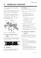
2. HANDLING CAUTIONS 2. HANDLING CAUTIONS This chapter describes important cautions regarding how to handle the transmitter. Read carefully before using the transmitter. The EJA-A Series pressure transmitters are thoroughly tested at the factory before shipment. When the transmitter is delivered, visually check them to make sure that no damage occurred during shipment. Also check that all transmitter mounting hardware shown in Figure 2.1.1 is included.
2. HANDLING CAUTIONS by high frequency noise pickup. To test for such effects, bring the transceiver in use slowly from a distance of several meters from the transmitter, and observe the measurement loop for noise effects. Thereafter, always use the transceiver outside the area affected by noise. (c) Shock and Vibration Select an installation site suffering minimum shock and vibration (although the transmitter is designed to be relatively resistant to shock and vibration).
2. HANDLING CAUTIONS 2) Turn OFF the dielectric strength tester. Then connect the tester between the shorted SUPPLY terminals and the grounding terminal. Be sure to connect the grounding lead of the dielectric strength tester to the ground terminal. WARNING To preserve the safety of explosionproof equipment requires great care during mounting, wiring, and piping. Safety requirements also place restrictions on maintenance and repair activities. Please read the following sections very carefully.
2. HANDLING CAUTIONS b. FM Explosionproof Type Caution for FM explosionproof type. • Entity Installation Requirements Vmax ≥ Voc or Vt, Imax ≥ Isc or It, Pmax (IS Apparatus) ≥ Pmax (Barrier) Ca ≥ Ci + Ccable, La ≥ Li + Lcable Note 1. Model EJA Series differential, gauge, and absolute pressure transmitters with optional code /FF1 are applicable for use in hazardous locations. • Applicable Standard: FM3600, FM3615, FM3810, ANSI/NEMA250 Note 3.
2. HANDLING CAUTIONS Note 1. For the installation of this transmitter, once a particular type of protection is selected, any other type of protection cannot be used. The installation must be in accordance with the description about the type of protection in this instruction manual. Note 2. In order to avoid confusion, unnecessary marking is crossed out on the label other than the selected type of protection when the transmitter is installed.
2. HANDLING CAUTIONS • When installed in Division 2, “SEALS NOT REQUIRED.” Note 3. Operation • Keep the “CAUTION” label attached to the transmitter. CAUTION: OPEN CIRCUIT BEFORE REMOVING COVER. OUVRIR LE CIRCUIT AVANT D´NLEVER LE COUVERCLE. • Take care not to generate mechanical sparking when accessing to the instrument and peripheral devices in a hazardous location. Note 4.
2. HANDLING CAUTIONS Note 3. Installation • In any safety barreir used output current must be limited by a resistor 'R' such that Io=Uo/R. • The safety barrier must be IECEx certified. • Input voltage of the safety barrier must be less than 250 Vrms/Vdc. • The instrument modification or parts replacement by other than authorized representative of Yokogawa Electric Corporation and will void IECEx Intrinsically safe and type n certification.
2. HANDLING CAUTIONS 2.9.4 CENELEC ATEX (KEMA) Certification [Installation Diagram] Hazardous Location (1) Technical Data Transmitter a. CENELEC ATEX (KEMA) Intrinsically Safe Type Caution for CENELEC ATEX (KEMA) Intrinsically safe type. Note 1. Model EJA Series differential, gauge, and absolute pressure transmitters with optional code /KS2 for potentially explosive atmospheres: • No.
2. HANDLING CAUTIONS • Take care not to generate mechanical sparking when accessing to the instrument and peripheral devices in a hazardous location. Note 5. Maintenance and Repair • The instrument modification or parts replacement by other than authorized representative of Yokogawa Electric Corporation is prohibited and will void KEMA Flameproof Certification. c.
2. HANDLING CAUTIONS (4) Operation WARNING • OPEN CIRCUIT BEFORE REMOVING COVER. INSTALL IN ACCORDANCE WITH THIS USER’S MANUAL • Take care not to generate mechanical sparking when access to the instrument and peripheral devices in hazardous locations. (5) Maintenance and Repair MWP: Maximum working pressure. CAL RNG: Specified calibration range. DISP MODE: Specified display mode. OUTPUT MODE: Specified output mode. NO.: Serial number and year of production*1.
2. HANDLING CAUTIONS • EJA130A, EJA440A, EJA510A, and EJA530A can be used above 200 bar and therefore considered as a part of a pressure retaining vessel where category lll, Module H applies. These models with option code /PE3 conform to that category. (3) Operation CAUTION • The temperature and pressure of fluid should be applied under the normal operating condition. • The ambient temperature should be applied under the normal operating condition.
3. COMPONENT NAMES 3. COMPONENT NAMES External indicator conduit connection (Note 1) Transmitter section Terminal box cover CPU assembly Zero-adjustment screw Integral indicator (Note 1) Pipe (Open to atmosphere) Mounting screw (Note 3) Setting pin (CN4) Capsule assembly Range-setting switch (Note 1) (See Subsection 7.5) Amplifier Cover Setting Pin (CN4) Position (Note 2) Burn-Out Direction Output at Burn-Out HIGH 110% or higher LOW -5% or lower H L H L F0301.
4. INSTALLATION 4. INSTALLATION 4.1 Precautions Vertical pipe mounting Before installing the transmitter, read the cautionary notes in Section 2.4, “Selecting the Installation Location.” For additional information on the ambient conditions allowed at the installation location, refer to Subsection 10.1 “Standard Specifications.” Adapter U-bolt (S) Plate U-bolt nut (S) IMPORTANT • When welding piping during construction, take care not to allow welding currents to flow through the transmitter.
4. INSTALLATION IMPORTANT IMPORTANT Tighten the hexagonal nut part of the capsule assembly. See Figure 4.2.3. Do not rotate the transmitter section more than 180°. Transmitter section Rotate 90° or 180° segments Capsule assembly Conduit connection Zero-adjustment screw Gasket Pipe Allen screw Capsule assembly F0403.EPS F0404.EPS Figure 4.2.3 Tightening Transmitter 4.3 Rotating Transmitter Section Figure 4.3 Rotating Transmitter Section 4.
5. INSTALLING IMPULSE PIPING 5. INSTALLING IMPULSE PIPING 5.1 Impulse Piping Installation Precautions 5.1.2 Routing the Impulse Piping (1) Process Pressure Tap Angles If condensate, gas, sediment or other extraneous material in the process piping gets into the impulse piping, pressure measurement errors may result. To prevent such problems, the process pressure taps must be angled as shown in Figure 5.1.2 according to the kind of fluid being measured. 5.1.
5. INSTALLING IMPULSE PIPING (2) Position of Process Pressure Taps and Transmitter If condensate (or gas) accumulates in the impulse piping, it should be removed periodically by opening the drain (or vent) plugs. However, this will generate a transient disturbance in the pressure measurement, and therefore it is necessary to position the taps and route the impulse piping so that any extraneous liquid or gas generated in the leadlines returns naturally to the process piping. 5.
6. WIRING 6. WIRING 6.1 Wiring Precautions IMPORTANT • Lay wiring as far as possible from electrical noise sources such as large capacity transformers, motors, and power supplies. • Remove electrical connection dust cap before wiring. • All threaded parts must be treated with waterproofing sealant. (A non-hardening silicone group sealant is recommended.) • To prevent noise pickup, do not pass signal and power cables through the same ducts.
6. WIRING (2) Intrinsically Safe Type For intrinsically safe type, a safety barrier must be included in the loop. 6.3.4 Check Meter Connection Connect the check meter to the CHECK + and – terminals (use hooks). • A 4 to 20 mA DC output signal from the CHECK + and – terminals. Hazardous Location (Note) Use a check meter whose internal resistance is 10 Ω or less.
6. WIRING (2) Flameproof Type Wire cables through a flameproof packing adapter, or using a flameproof metal conduit. 䊏 Wiring cable through flameproof packing adapter. • Apply a nonhardening sealant to the terminal box connection port and to the threads on the flameproof packing adapter for waterproofing. Apply a non-hardening sealant to the threads for waterproofing. 6.5 Grounding Grounding is always required for the proper operation of transmitters.
7. OPERATION 7. OPERATION Confirming that Transmitter is Operating Properly Using the BT200 • If the wiring system is faulty, ‘communication error’ appears on the display. • If the transmitter is faulty, ‘SELF CHECK ERROR’ appears on the display. 7.1 Preparation for Starting Operation This section describes the operation procedure for measuring a pressure as shown in Figure 7.1. NOTE PARAM C60:SELF CHECK ERROR Confirm that the process pressure tap valve, drain valve, and stop valve are closed.
7. OPERATION 7.2.1 When you can obtain Low Range Value from actual measured value of 0% (0 kPa, atmospheric pressure); 7.2 Zero Point Adjustment Adjust the zero point after operating preparation is completed. For pressure measurement using gauge pressure transmitters, follow the step below before zero point adjustment. 1) Close the tap valve (main valve). 2) Loosen the fill plug so that the pressure applied to the transmitter is only the head of the seal liquid. 3) Adjust the zero point at this status.
7. OPERATION 7.2.2 When you cannot obtain Low Range Value from actual measured value of 0%; 7.3 Starting Operation After completing the zero point adjustment, follow the procedure below to start operation. Convert the actual measured value obtained by a digital manometer or a glass gauge into %. 1) Confirm the operating status. If the output signal exhibits wide fluctuations (hunting) due to periodic variation in the process pressure, use BT200 to dampen the transmitter output signal.
7. OPERATION 7.5 Setting the Range Using the Range-setting Switch IMPORTANT • Do not turn off the power to the transmitter immediately after completion of the change in the LRV and/or HRV setting(s). Note that powering off within thirty seconds after setting will cause a return to the previous settings. • Changing LRV automatically changes HRV to the following value.
8. BRAIN TERMINAL BT200 OPERATION 8. BRAIN TERMINAL BT200 OPERATION The DPharp is equipped with BRAIN communications capabilities, so that range changes, Tag No. setup, monitoring of self-diagnostic results, and zero point adjustment can be handled by remote control via BT200 BRAIN TERMINAL or CENTUM CS console. This section describes procedures for setting parameters using the BT200. For details concerning the BT200, see IM 01C00A11-01E, “BT200 User’s Manual.” 8.2 BT200 Operating Procedures 8.2.
8. BRAIN TERMINAL BT200 OPERATION 8.2.2 Operating Key Functions (1) Alphanumeric Keys and Shift Keys You can use the alphanumeric keys in conjunction with the shift keys to enter symbols, as well as alphanumeric keys. Use the function key [F1] CODE to enter symbols. The following symbols will appear in sequence, one at a time, at the cursor each time you press [F1] CODE: / . – , + * ) ( ’ & % $ # ” ! To enter characters next to these symbols, press [ > ] to move the cursor.
8. BRAIN TERMINAL BT200 OPERATION 8.2.3 Calling Up Menu Addresses Using the Operating Keys ––WELCOME–– BRAIN TERMINAL ID: BT200 STARTUP SCREEN check connection push ENTER key UTIL The utility screen contains the following items. 1. BT200 ID settings 2. Security code settings 3. Switching language of messages (Japanese or English) 4. LCD contrast setting 5. Adjusting printout tone (BT200-P00 only) UTILITY 1.ID 2.SECURITY CODE 3.LANGUAGE SELECT 4.LCD CONTRAST 5.
8. BRAIN TERMINAL BT200 OPERATION 8.3 Setting Parameters Using the BT200 8.3.1 Parameter Summary Instruments to which applicable: F: Differential pressure transmitters P: Pressure transmitters L: Liquid level transmitters No. Item 01 MODEL 02 TAG NO. EJA110A, EJA120A, and EJA130A EJA310A, EJA430A, EJA440A, EJA510A, and EJA530A EJA210A and EJA220A Description Model+capsule type Tag number 03 SELF CHECK Self-diagnostic result A DISPLAY Measured data display A10 OUTPUT (%) A11 ENGR.
8. BRAIN TERMINAL BT200 OPERATION No. D Item AUX SET 1 D31 STAT. P.
8. BRAIN TERMINAL BT200 OPERATION 8.3.2 Parameter Usage and Selection IMPORTANT Before describing the procedure for setting parameters, we present the following table showing how the parameters are used and in what case. If the transmitter is turned off within 30 seconds after parameters have been set, the set data will not be stored and the terminal returns to previous settings. Table 8.3.1 Parameter Usage and Selection Setup Item Tag No. setup P.8-7 Calibration range setup P.
8. BRAIN TERMINAL BT200 OPERATION 8.3.3 Setting Parameters Set or change the parameters as necessary. After completing these, do not fail to use the “DIAG” key to confirm that “GOOD” is displayed for the selfdiagnostic result at _60: SELF CHECK. set data. The set data items flash. When all items have been confir- PRINTER OFF F2:PRINTER ON FEED POFF NO med, press the again. (To go back to the setting panel, press the (NO) key. (1) Tag No. Setup (C10: TAG NO) Use the procedure below to change the Tag No.
8. BRAIN TERMINAL BT200 OPERATION b. Setting Calibration Range Lower Range Value and Higher Range Value (C21: LOW RANGE, C22: HIGH RANGE) These range values are set as specified in the order before the instrument is shipped. Follow the procedure below to change the range. • Example 2: With present settings of 0 to 30 kPa, set the Higher range value to10 kPa.
8. BRAIN TERMINAL BT200 OPERATION (4) Output Signal Low Cut Mode Setup (D10: LOW CUT, D11: LOW CUT MODE) Low cut mode can be used to stabilize the output signal near the zero point. The low cut point can be set in a range from 0 to 20% of output. (Hysteresis of cut point: ±1%) LOW CUT at 10% (5) Change Output Limits (D15:OUT LIMIT(L), D16:OUT LIMIT(H)) The range of normal output is preset at factory from -5.0 to 110.
8. BRAIN TERMINAL BT200 OPERATION (6) Integral Indicator Scale Setup The following 5 displays are available for integral indicators. D20: DISP SELECT Display Related Parameters Description NORMAL % A10:OUTPUT (%) 45.6 % Indicates –5 to 110% range depending on the Measurement range (C21, C22). USER SET A11:ENGR.OUTPUT 20.0 M Indicates values depending on the Engineering range (D22, D23). (Note 1) Units set using Engineering unit (D21) are not indicated.
8. BRAIN TERMINAL BT200 OPERATION a. Display Selection (D20: DISP SELECT) Follow the instructions given to the below to change the range of integral indication scales. When USER SET is selected, the user set values of integral indication and A11: ENGR. OUTPUT parameter are indicated. • Example: Set the integral indicator scale to engineering units display. Use the SET D20:DISP SELECT NORMAL % or c.
8. BRAIN TERMINAL BT200 OPERATION (8) Operation Mode Setup (D40: REV OUTPUT) This parameter allows the direction of the 4 to 20 mA output to be reversed with respect to input. Follow the procedure below to make this change. (a) HOLD; Outputs the last value held before the error occurred. (b) HIGH; Outputs an output of 110% when an error has occurred. (c) LOW; Outputs an output of –5% when an error has occurred. • Example: Change 4 to 20 mA output to 20 to 4 mA output.
8. BRAIN TERMINAL BT200 OPERATION Note that changing the higher range value does not cause the lower range value to change but does change the span. (a) Follow the procedure below when setting the present output to 0% (4 mA). Output is 0.5%. A10:OUTPUT (%) 0.5 % • Example 2: When the higher range value is to be changed to 10 kPa with the present setting of 0 to 30 kPa, take the following action with an input pressure of 10 kPa applied. SET J10:ZERO ADJ 0.0 % + 000.
8. BRAIN TERMINAL BT200 OPERATION (b)-2 Follow the procedure below to use J11: ZERO DEV. • Example: Inhibiting zero adjustment by the external zero-adjustment screw SET J20:EXIT ZERO ADJ ENABLE < ENABLE > < INHIBIT> Present output is 41.0%. A10:OUTPUT (%) 41.0 % Output error = 40.0 – 41.0 = –1.0%. Use the Press the SET J11:ZERO DEV. 2.50 % 0 Since “J11: ZERO DEV.” contains or key to select “INHIBIT.” ESC key twice to enter the setting. the previous correction, obtain the F0831.
8. BRAIN TERMINAL BT200 OPERATION • Span adjustment value The span adjustment value is calculated as follows. Span adjustment value (%) = P1 A40 100 P1 P1: Actual differential pressure/pressure value A40: Input (indicated as the value after zeroing) (14) Test Output Setup (K10: OUTPUT X%) This feature can be used to output a fixed current from 3.2 mA (–5%) to 21.6 mA (110%) for loop checks. • Example: Output 12 mA (50%) fixed current. SET K10:OUTPUT X % 0.0 % + 050.0 Measurement pressure Set “50.
8. BRAIN TERMINAL BT200 OPERATION 8.4 Displaying Data Using the BT200 8.4.1 Displaying Measured Data The BT200 can be used to display measured data. The measured data is updated automatically every 7 seconds. In addition, the display can be updated to the present data value at any time by pressing the (DATA) key. For parameters associated with the display of measured data, see Subsection 8.3.1, “Parameter Summary.” 8.5 Self-Diagnostics 8.5.
8. BRAIN TERMINAL BT200 OPERATION • Example 3: Checking the history of the errors Connect the BT200 to the transmitter, and call item “P.” MENU J:ADJUST K:TEST M:MEMO P:RECORD HOME SET (2) Checking with Integral Indicator ADJ ESC PARAM P10:ERROR REC 1 ERROR P11:ERROR REC 2 ERROR P12:ERROR REC 3 GOOD DATA DIAG PRNT ESC NOTE If an error is detected in the self-diagnostic, an error number is displayed on the integral indicator.
8. BRAIN TERMINAL BT200 OPERATION 8.5.2 Errors and Countermeasures The table below shows a summary of error messages. Table 8.5.1 Error Message Summary Integral Indicator Display BT200 Display Cause Output Operation during Error Countermeasure None GOOD ---- ERROR Er. 01 CAP MODULE FAULT Capsule problem.*1 Outputs the signal (Hold, High, or Low) set with parameter D53. Replace the capsule when error keeps appearing even after restart.*2 Er. 02 AMP MODULE FAULT Amplifier problem.
9. MAINTENANCE 9. MAINTENANCE 9.1 Overview WARNING Since the accumulated process fluid may be toxic or otherwise harmful, take appropriate care to avoid contact with the body, or inhalation of vapors even after dismounting the instrument from the process line for maintenance. 9.2 Calibration Instruments Selection Table 9.2.1 shows the instruments required for calibration. Select instruments that will enable the transmitter to be calibrated or adjusted to the required accuracy.
9. MAINTENANCE Table 9.2.1 Instruments Required for Calibration Name Power supply Load resistor Voltmeter Digital manometer Pressure generator Pressure source Yokogawa-recommended Instrument Remarks 4 to 20 mA DC signal Model SDBT or SDBS distributor Model 2792 standard resistor [250 Ω ±0.005%, 3 W] Load adjustment resistor [100 Ω ±1%, 1 W] Model 2501 A digital multimeter Accuracy (10V DC range): ±(0.002% of rdg + 1 dgt) Model MT220 precision digital manometer 1) For 10 kPa class Accuracy: ±(0.
9. MAINTENANCE 9.4 Disassembly and Reassembly Shrouding Bolt CAUTION Precautions for CENELEC and IECEx Flameproof Type Transmitters • Flameproof type transmitters must be, as a rule, removed to a non-hazardous area for maintenance and be disassembled and reassembled to the original state. • On the flameproof type transmitters the two covers are locked, each by an Allen head bolt (shrouding bolt).
9. MAINTENANCE Attaching the Integral Indicator Integral indicator can be installed in the following three directions. F0910.EPS 3) Disconnect the output terminal cable (cable with brown connector at the end). When doing this, lightly press the side of the CPU assembly connector and pull the cable connector to disengage. 4) Use a socket driver (width across flats, 5.5mm) to loosen the two bosses. 5) Carefully pull the CPU assembly straight forward to remove it.
9. MAINTENANCE 9.4.3 Cleaning and Replacing the Capsule Assembly This subsection describes the procedures for cleaning and replacing the capsule assembly. (See Figure 9.4.3.) CAUTION Cautions for Flameproof Type Transmitters Users are prohibited by law from modifying the construction of a flameproof type transmitter. If you wish to replace the capsule assembly with one of a different measurement range, contact Yokogawa.
9. MAINTENANCE 9.5.1 Basic Troubleshooting 9.5 Troubleshooting First determine whether the process variable is actually abnormal or a problem exists in the measurement system. If any abnormality appears in the measured values, use the troubleshooting flow chart below to isolate and remedy the problem. Since some problems have complex causes, these flow charts may not identify all. If you have difficulty isolating or correcting a problem, contact Yokogawa service personnel.
9. MAINTENANCE Output travels beyond 0% or 100%. Connect BRAIN TERMINAL and check self-diagnostics. YES Does the self-diagnostic indicate problem location? Refer to error message summary in Subsection 8.5.2 to take actions. NO NO Refer to Section 6.3 to check/correct polarity at each terminal from power supply to the terminal box. NO Fully close equalizing valve, and fully open high pressure and low pressure valves.
10. GENERAL SPECIFICATIONS 10. GENERAL SPECIFICATIONS 10.1 Standard Specifications Damping Time Constant (1st order): The sum of the amplifier and capsule damping time constant must be used for the overall time constant. Amp damping time constant is adjustable from 0.2 to 64 seconds. Refer to IM 01C22T02-01E for FOUNDATION Fieldbus communication type and IM 01C22T0300E for PROFIBUS PA communication type marked with “ ”.
10. GENERAL SPECIFICATIONS Physical Specifications EMC Conformity Standards “ ”: , EN61326-1 Class A, Table 2 (For use in industrial lications) EN61326-2-3 Wetted Parts Materials: Diaphragm and Process connector; See ‘Model and Suffix Codes.’ Non-wetted Parts Materials: Housing; Low copper cast-aluminum alloy with polyurethane paint (Munsell 0.6GY3.1/2.
10. GENERAL SPECIFICATIONS 10.2 Model and Suffix Codes Model EJA510A and EJA530A Suffix Codes Description . . . . . . . . . . . . . . . . . . . . Absolute pressure transmitter . . . . . . . . . . . . . . . . . . . . Gauge pressure transmitter -D . . . . . . . . . . . . . . . . . 4 to 20 mA DC with digital communication (BRAIN protocol) Output Signal -E . . . . . . . . . . . . . . . . . 4 to 20 mA DC with digital communication (HART protocol, see IM 01C22T01-01E) -F . . . . . . . . . . . . . . . . .
10. GENERAL SPECIFICATIONS 10.3 Optional Specifications For FOUNDATION Fieldbus explosion protected type, see IM 01C22T02-01E. For PROFIBUS PA explosion protected type, see IM 01C22T03-00E. Item Description Factory Mutual (FM) CENELEC ATEX Code FM Explosionproof Approval *1 Explosionproof for Class I, Division 1, Groups B, C and D Dust-ignitionproof for Class II/III, Division 1, Groups E, F and G Hazardous (classified) locations, indoors and outdoors (NEMA 4X) Temperature class: T6 Amb. Temp.
10. GENERAL SPECIFICATIONS Item Description Canadian Standards Association (CSA) Code CSA Explosionproof Approval *1 Certificate: 1089598 Explosionproof for Class I, Division 1, Groups B, C and D Dustignitionproof for Class II/III, Division 1, Groups E, F and G Division2 ‘SEALS NOT REQUIRED’ , Temp. Class: T4, T5, T6 Encl Type 4x Max. Process Temp.: T4; 120⬚C (248⬚F), T5; 100⬚C (212⬚F), T6; 85⬚C (185⬚F) Amb. Temp.
10. GENERAL SPECIFICATIONS Item Description Code Amplifier cover only P Amplifier cover and terminal cover, Munsell 7.5 R4/14 PR Epoxy resin-baked coating X1 316 SST exterior parts Exterior parts on the amplifier housing (name plates, tag plate, zero-adjustment screw, stopper screw) will become 316 or 316L SST. HC Lightning protector Transmitter power supply voltage: 10.5 to 32 V DC (10.
10. GENERAL SPECIFICATIONS 10.4 Dimensions Model EJA510A and EJA530A [Style: S2] With Process Connection code 7 Unit: mm(Approx. inch) 110(4.33) 41(1.61) 12 (0.47) 170(6.69) 127(5.0) Shrouding bolt *2 45 (1.77) 78 (3.07) Conduit connection LOCK Zero adjustment ZERO LOCK Ground terminal 111(4.37) 96(3.77) 124(4.88) Adapter Pipe(Open to atmosphere)*1 47 (1.85) 44(1.73) 2-inch pipe (O. D. 60.5 mm) 91(3.
Customer Maintenance Parts List Model EJA510A and EJA530A Absolute and Gauge Pressure Transmitter 2 5 4 11 A 10 3 12 1 13 2 2 1 14 A 6 7-1 7-2 8 5 9 18 17 16 15 15 15 Process connection code 4 Process connection code 8 and 9 Process connection code 7 21 19 22 24 20 23 All Rights Reserved, Copyright © 1999, Yokogawa Electric Corporation. CMPL 01C21F01-01E 6th Edition: Oct.
2 Item Part No.
REVISION RECORD Title: Model EJA510A and EJA530A Absolute Pressure and Gauge Pressure Transmitter Manual No.: IM 01C21F01-01E Edition Date Page 1st June 1999 – 2nd June 2000 CONTENTS 2-8 8-4 8-5 10-4 10-5 CMPL 3rd Aug. 2001 – 2-8 8-4, 8-5 10-1 10-4 10-6 CMPL 4th May 2002 1-2 2-7 10-4 10-5 5th Apr. 2003 2-8 2-10 10-3 10-4 10-5 CMPL Revised Item New publication Page 3 2.9.4 b. • Add REVISION RECORD. • Add maximum process temperature of –40 to 75°C for KEMA Flameproof type T6.
Edition Date Page 6th Apr. 2006 1-2 1-3 2-6 2-11 10-4, 10-5 10-5 10-6 7th Jan. 2008 1-1 1-4 2-3+ 2-10 4-2 8-14 9-4 10-1+ 10-4, -5 CMPL 8th Oct. 2008 2-9 2-10 8-4 and 8-5 8-6 8-9 and later 8-18 9-1 9-5 10-3 10-5, 10-6 CMPL Revised Item 1.1 1.3 2.9.3 2.12 10.3 • Add (e) Explosion Protected Type Instrument and (f) Modification • Add “1.