
Instruction Manual


IM 01C21F01-01E
3-1
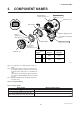
3. COMPONENT NAMES
3. COMPONENT NAMES
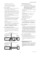
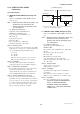
Setting pin (CN4)
Integral
indicator
(Note 1)
CPU assembly
External indicator
conduit connection
(Note 1)
Transmitter section
Te r minal box cover
Zero-adjustment screw
Pipe (Open to atmosphere)
(Note 3)
Capsule assembly
Mounting screw
Range-setting
switch
(Note 1)
(See Subsection 7.5)
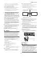
Amplifier Cover
Setting Pin (CN4)
Position
(Note 2)
Burn-Out
Direction
Output at
Burn-Out
H
L
H
L
HIGH
LOW
110% or
higher
-
5% or
lower
F0301.EPS
Note 1: See Subsection 10.2, “Model and Suffix Codes,” for
details.
Note 2: Insert the pin (CN4) as shown in the figure above to
set the burn-out direction. The pin is set to the H side
for delivery (unless option code /C1 is specified in the
order).
The setting can be confirmed by calling up parameter
D52 using the BRAIN TERMINAL. Refer to Subsection
8.3.3 (8).
Note 3: Applied to Model EJA530A with Measurement span
code A, B, and C.
Figure 3.1 Component Names
Table 3.1 Display Symbol
Display Symbol
%, Pa, kPa, MPa, kgf/cm
2
, gf/cm
2
, mbar, bar,
atm, mmHg, mmH
2
O, inH
2
O, inHg, ftH
2
O, psi, Torr
Meaning of Display Symbol
The output signal being zero-adjusted is increasing.
The output signal being zero-adjusted is decreasing.
Select one of these sixteen available engineering units for the display.
T0301.EPS