User’s Manual Absolute Pressure and Gauge Pressure Transmitters EJ510, EJ530, EJX610A and EJX630A IM 01C25F01-01E IM 01C25F01-01E 10th Edition
i Absolute Pressure and Gauge Pressure Transmitters EJ510, EJ530, EJX610A and EJX630A IM 01C25F01-01E 10th Edition Contents 1. Introduction................................................................................................ 1-1 Regarding This Manual................................................................................................. 1-1 2. 1.1 Safe Use of This Product ................................................................................. 1-2 1.2 Warranty.....
ii 6. Wiring.......................................................................................................... 6-1 6.1 Wiring Precautions............................................................................................ 6-1 6.2 Selecting the Wiring Materials.......................................................................... 6-1 6.3 Connections of External Wiring to Terminal Box........................................... 6-1 6.4 7. 8. Power Supply Wiring Connection.........
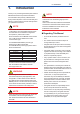
1. 1-1 <1. Introduction> Introduction Thank you for purchasing the DPharp EJX and EJA Differential Pressure and pressure transmitter. Your transmitter was precisely calibrated at the factory before shipment. To ensure both safety and efficiency, please read this manual carefully before you operate the instrument. NOTE This manual describes the hardware configurations of the transmitters listed in below.
• The following safety symbols are used in this manual: WARNING Indicates a potentially hazardous situation which, if not avoided, could result in death or serious injury. CAUTION Indicates a potentially hazardous situation which, if not avoided, may result in minor or moderate injury. It may also be used to alert against unsafe practices. IMPORTANT Indicates that operating the hardware or software in this manner may damage it or lead to system failure.
(c) Operation • Wait 5 min. after the power is turned off, before opening the covers. (d) Maintenance • Please carry out only the maintenance procedures described in this manual. If you require further assistance, please contact the nearest Yokogawa office. • Care should be taken to prevent the build up of dust or other materials on the display glass and the name plate. To clean these surfaces, use a soft, dry cloth.
1.3 <1. Introduction> 1-4 ATEX Documentation This is only applicable to the countries in European Union.
2. 2-1 <2. Handling Cautions> Handling Cautions This chapter provides important information on how to handle the transmitter. Read this carefully before using the transmitter. The transmitters are thoroughly tested at the factory before shipment. When taking delivery of an instrument, visually check them to make sure that no damage occurred during shipment. Also check that all transmitter mounting hardware shown in figure 2.1 is included.
(a) Ambient Temperature Avoid locations subject to wide temperature variations or a significant temperature gradient. If the location is exposed to radiant heat from plant equipment, provide adequate thermal insulation and/or ventilation. (b) Ambient Atmosphere Do not install the transmitter in a corrosive atmosphere. If this cannot be avoided, there must be adequate ventilation as well as measures to prevent the leaking of rain water and the presence of standing water in the conduits.
<2. Handling Cautions> 2-3 (b) Never apply a voltage exceeding 500 V DC (100 V DC with an internal lightning protector) for the insulation resistance test, nor a voltage exceeding 500 V AC (100 V AC with an internal lightning protector) for the dielectric strength test. (c) Before conducting these tests, disconnect all signal lines from the transmitter terminals. The procedure for conducting these tests is as follows: 2.
IMPORTANT For combined approval types Once a device of multiple approval type is installed, it should not be re-installed using any other approval types. Apply a permanent mark in the check box of the selected approval type on the certification label on the transmitter to distinguish it from unused approval types. IMPORTANT All the blind plugs which accompany the EJX/ EJA-E transmitters upon shipment from the factory are certified by the applicable agency in combination with the transmitters.
<2. Handling Cautions> Note 4. Maintenance and Repair • The instrument modification or parts replacement by other than authorized representative of Yokogawa Electric Corporation is prohibited and will void Factory Mutual Intrinsically safe and Nonincendive Approval. Note 2. Wiring • All wiring shall comply with National Electrical Code ANSI/NFPA70 and Local Electrical Codes. • When installed in Division 1, “FACTORY SEALED, CONDUIT SEAL NOT REQUIRED.
2.9.2 CSA Certification a. CSA Intrinsically Safe Type Caution for CSA Intrinsically safe and nonincendive type. (Following contents refer to “DOC No. ICS013-A13”) Note 1. Model EJX/EJA-E Series differential, gauge, and absolute pressure transmitters with optional code /CS1 are applicable for use in hazardous locations Certificate: 1606623 [For CSA C22.2] • Applicable Standard: C22.2 No.0, C22.2 No.0.4, C22.2 No.25, C22.2 No.94, C22.2 No.157, C22.2 No.213, C22.2 No.61010-1, C22.2 No.
<2. Handling Cautions> • Explosion-proof for Class I, Groups B, C and D. • Dustignition-proof for Class II/III, Groups E, F and G. • Enclosure: NEMA TYPE 4X • Temperature Code: T6...T4 • Ex d IIC T6...T4 • Enclosure: IP66/IP67 • Maximum Process Temperature: 120°C (T4), 100°C (T5), 85°C (T6) • Ambient Temperature: –50* to 75°C (T4), –50* to 80°C (T5), –50* to 75°C (T6) * –15°C when /HE is specified. • Supply Voltage: 42 V dc max. • Output Signal: 4 to 20 mA dc Note 2.
2.9.3 ATEX Certification (1) Technical Data a. ATEX Intrinsically Safe Ex ia Caution for ATEX Intrinsically safe type. Note 1. Model EJX/EJA-E Series pressure transmitters with optional code /KS21 for potentially explosive atmospheres: • No.
b. ATEX Flameproof Type Note 5. Special Conditions for Safe Use Caution for ATEX flameproof type. WARNING Note 1. Model EJX/EJA-E Series pressure transmitters with optional code /KF22 for potentially explosive atmospheres: • No. KEMA 07ATEX0109 X • Applicable Standard: EN 60079-0:2009, EN 60079-1:2007, EN 60079-31:2009 • Type of Protection and Marking Code: Ex d IIC T6...
● ATEX Intrinsically Safe Ex ic WARNING Caution for ATEX intrinsically safe Ex ic • Applicable Standard: EN 60079-0:2009/EN 60079-0:2012, EN 60079-11:2012 • Type of Protection and Marking Code: II 3G Ex ic IIC T4 Gc • Ambient Temperature: –30* to +60°C * –15°C when /HE is specified. • Ambient Humidity: 0 to 100% (No condensation) • Maximum Process Temperature: 120°C • IP Code: IP66 • Ambient pollution degree: 2 • Overvoltage category: I Note 1. Electrical Data Ui = 30 V Ci = 27.
2-11 <2. Handling Cautions> (5) Maintenance and Repair *1: The first digit in the three numbers next to the nine letters of the serial number appearing after “NO.” on the nameplate indicates the year of production. The following is an example of a serial number for a product that was produced in 2010: WARNING 91K819857 The instrument modification or parts replacement by other than an authorized Representative of Yokogawa Electric Corporation is prohibited and will void the certification.
<2. Handling Cautions> • Installation Requirements Uo ≤ Ui, Io ≤ Ii, Po ≤ Pi, Co ≥ Ci + Ccable, Lo ≥ Li + Lcable Voc ≤ Vmax, Isc ≤ Imax, Ca ≥ Ci + Ccable, La ≥ Li + Lcable Uo, Io, Po, Co, Lo, Voc, Isc, Ca and La are parameters of barrier. Note 3. Installation • In any safety barrier used output current must be limited by a resistor 'R' such that Io=Uo/R. • The safety barrier must be IECEx certified. • Input voltage of the safety barrier must be less than 250 Vrms/Vdc.
2.11 Pressure Equipment Directive (PED) (3) Operation CAUTION (1) General • EJX/EJA-E Series pressure transmitters are categorized as piping under the pressure accessories section of directive 97/23/EC, which corresponds to Article 3, Paragraph 3 of PED, denoted as Sound Engineering Practice (SEP). • EJ510-D, EJ530-D, EJX610A-D, and EJX630A-D can be used above 200 bar and therefore considered as a part of a pressure retaining vessel where category III, Module H applies.
3. 3-1 <3. Component Names> Component Names External indicator conduit connection (Note 1) Conduit connection Zeroadjustment screw (Note 2) Slide switch Integral indicator (Note 1) Mounting screw CPU assembly Range-setting switch (Note 1) (See section 7.
4. 4.1 <4. Installation> 4-1 Installation Precautions Before installing the transmitter, read the cautionary notes in section 2.4, “Selecting the Installation Location.” For additional information on the ambient conditions allowed at the installation location, refer to section 9.1 “Standard Specifications.
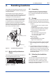
4-2 <4. Installation> Transmitter section IMPORTANT Tighten the hexagonal nut part of the capsule assembly. See Figure 4.3. Setscrew Capsule assembly Pressure-detector section Stopper Figure 4.4 F0404.ai Rotating Transmitter Section F0403.ai Figure 4.3 4.
5. 5.1 5-1 <5. Installing Impulse Piping> Installing Impulse Piping Impulse Piping Installation Precautions The impulse piping that connects the process outputs to the transmitter must convey the process pressure accurately. If, for example, gas collects in a liquidfilled impulse line, or the drain for a gas-filled impulse line becomes plugged, it will not convey the pressure accurately.
<5. Installing Impulse Piping> (3) Impulse Piping Slope Tap valve The impulse piping must be routed with only an upward or downward slope. Even for horizontal routing, the impulse piping should have a slope of at least 1/10 to prevent condensate (or gases) from accumulating in the pipes.
6-1 <6. Wiring> 6.1 Wiring Precautions 6.3 IMPORTANT • Lay wiring as far as possible from electrical noise sources such as large capacity transformers, motors, and power supplies. • Remove the electrical connection dust cap before wiring. • All threaded parts must be treated with waterproofing sealant. (A non-hardening silicone group sealant is recommended.) • To prevent noise pickup, do not pass signal and power cables through the same ducts.
6-2 <6. Wiring> 6.3.4 Check Meter Connection (1) General-use Type and Flameproof Type Available only when /AL is not specified. Hazardous Location Connect the check meter to the CHECK + and – terminals. (Use hooks.) Transmitter terminal box Distributor (Power supply unit) PULSE • A 4 to 20 mA DC output signal from the CHECK + and – terminals. Nonhazardous Location SUPP LY CHECKM ALAR Receiver instrument (Note) Use a check meter whose internal resistance is 10 Ω or less.
6-3 <6. Wiring> (2) Flameproof Type 6.5 Wire cables through a flameproof packing adapter, or use a flameproof metal conduit. Grounding is always required for the proper operation of transmitters. Follow the domestic electrical requirements as regulated in each country. For a transmitter with a built-in lightning protector, grounding should satisfy ground resistance of 10Ω or less. ■ Wiring cable through flameproof packing adapter.
7-1 <7. Operation> 7. Operation 7.1 Preparation for Starting Operation Tap valve Vent plug (Fill plug) This section describes the operation procedure for the EJ530 as shown in figure 7.1. Union or flange NOTE Stop valve Check that the process pressure tap valves, drain valves, and stop valves are closed. (a) Follow the procedures below to introduce process pressure into the impulse piping and transmitter. 1) Open the tap valve (main valve) to fill the impulse piping with process fluid.
7-2 <7. Operation> Using the integral indicator • If the wiring system is faulty, the display stays blank. • If the transmitter is faulty, an error code is displayed. IMPORTANT Do not turn off the power to the transmitter immediately after performing a zero point adjustment. Powering off within 30 seconds of performing this procedure will return the zero point to its previous setting. NOTE Self-diagnostic error on the integral indicator (Faulty transmitter) Figure 7.3 F0703.
Use a slotted screwdriver to turn the zeroadjustment screw. Turn the screw clockwise to increase the output or counterclockwise to decrease the output. The zero point adjustment can be made with a resolution of 0.01% of the setting range. Since the degree of the zero adjustment varies with the screw turning speed, turn the screw slowly to make a fine adjustment and quickly to make a rough adjustment.
7.5 Setting the Range Using the Range-setting Switch WARNING The range setting switch must not be used in the hazardous area. When it is necessary to use the switch, operate it in a non-hazardous location. <7. Operation> 7-4 Note 1: Wait until the pressure inside the pressure-detector section has stabilized before proceeding to the next step. Note 2: If the pressure applied to the transmitter exceeds the previous LRV (or URV), the integral indicator may display error number “AL.
8. 8.1 Maintenance Overview 8.3 WARNING Use the procedure below to check instrument operation and accuracy during periodic maintenance or troubleshooting. Since the accumulated process fluid may be toxic or otherwise harmful, take appropriate care to avoid contact with the body or inhalation of vapors when draining condensate or venting gas from the transmitter pressure-detector section and even after dismounting the instrument from the process line for maintenance.
Table 8.1 Name Power supply Load resistor Voltmeter Digital manometer Pressure generator Pressure source 8-2 <8. Maintenance> Instruments Required for Calibration Yokogawa-recommended Instrument Model SDBT or SDBS distributor Model 2792 standard resistor [250 Ω ±0.005%, 3 W] Load adjustment resistor [100 Ω ±1%, 1 W] Model 2501 A digital multimeter Accuracy (10V DC range): ±(0.002% of rdg + 1 dgt) Model MT220 precision digital manometer 1) For 10 kPa class Accuracy: ±(0.015% of rdg + 0.015% of F.S.) .
8.4 Disassembly and Reassembly 8.4.1 Replacing the Integral Indicator This section describes procedures for disassembly and reassembly for maintenance and component replacement. Always turn OFF power and shut off and release pressures before disassembly. Use proper tools for all operations. Table 8.2 shows the tools required. Table 8.2 8-3 <8.
8.4.2 Replacing the CPU Board Assembly This subsection describes the procedure for replacing the CPU assembly. (See figure 8.3) ■ Removing the CPU Assembly 1) Remove the cover. If an integral indicator is mounted, refer to subsection 8.4.1 and remove the indicator. 2) Turn the zero-adjustment screw to the position (where the screw head slot is horizontal) as shown in figure 8.3. 3) Disconnect the output terminal cable (cable with brown connector at the end).
■ Removing the Capsule Assembly IMPORTANT Exercise care as follows when cleaning the capsule assembly. • Handle the capsule assembly with care, and be especially careful not to damage or distort the diaphragms that contact the process fluid. • Do not use a chlorinated or acidic solution for cleaning. • Rinse thoroughly with clean water after cleaning. 1) Remove the CPU assembly as shown in subsection 8.4.2. 2) Remove the two setscrews that connect the transmitter section and pressure-detector section.
8.5.1 Basic Troubleshooting 8.5.2 Troubleshooting Flowcharts First determine whether the process variable is actually abnormal or a problem exists in the measurement system. The following sorts of symptoms indicate that transmitter may not be operating properly. Example : • There is no output signal. • Output signal does not change even though process variable is known to be varying. • Output value is inconsistent with value inferred for process variable.
8-7 <8. Maintenance> Large output error. Output travels beyond 0% or 100%. Connect a communicator and check self-diagnostics. Connect a communicator and check self-diagnostics. Does the selfdiagnostic indicate problem location? NO Refer to error message summary in each communication manual to take actions. Refer to Section 6.3 to check/correct polarity at each terminal from power supply to the terminal box.
8-8 <8. Maintenance> 8.5.3 Alarms and Countermeasures Table 8.3 Indicator None AL. 01 CAP. ERR AL. 02 AMP. ERR AL. 10 PRESS AL. 11 ST. PRSS AL. 12 CAP. TMP AL. 13 AMP. TMP AL. 30 RANGE AL. 31 SP. RNG AL. 35 *1 P. HI AL. 36 *1 P. LO AL. 39 *1 TMP. HI AL. 40 *1 TMP. LO AL. 50 P. LRV AL. 51 P. URV AL. 52 P. SPN AL. 53 P. ADJ AL. 60 SC. CFG AL. 79 OV. DISP Alarm Message Summary Cause Sensor problem. Capsule temperature sensor problem. Capsule EEPROM problem. Amplifier temperature sensor problem.
9. 9.1 General Specifications Standard Specifications EJX610A (Values are absolute pressure) Refer to IM 01C25T02-01E for FOUNDATION Fieldbus communication type and IM 01C25T0401EN for PROFIBUS PA communication type for the items marked with “◊”. Performance Specifications Measurement Span/Range A B C See General Specifications sheet for each model.
9-2 <9. General Specifications> Failure Alarm “◊” Output status at CPU failure and hardware error; Up-scale: 110%, 21.6 mA DC or more (standard) Down-scale: –5%, 3.2 mA DC or less Note: Applicable for Output signal code D and E Damping Time Constant (1st order) Amplifier damping time constant is adjustable from 0 to 100.00 seconds and added to response time. Note: For BRAIN protocol type, when amplifier damping is set to less than 0.
9-3 <9. General Specifications> Atmospheric pressure 100(14.5) Working pressure kPa abs (psia) 10(1.4) Supply & Load Requirements “◊” (Optional features or approval codes may affect electrical requirements.) With 24 V DC supply, up to a 550 Ω load can be used. See graph below. Applicable range 600 2.7(0.38) 1(0.14) -40 0 40 80 120 (-40) (32) (104) (176) (248) Process temperature °C (°F) Figure 9.
Communication Requirements “◊” (Safety approvals may affect electrical requirements.) BRAIN Communication Distance Up to 2 km (1.25 miles) when using CEV polyethylene-insulated PVC-sheathed cables. Communication distance varies depending on type of cable used. Load Capacitance 0.22 μF or less Load Inductance 3.3 mH or less Input Impedance of communicating device 10 kΩ or more at 2.4 kHz. HART Communication Distance Up to 1.5 km (1 mile) when using multiple twisted pair cables.
9.2 9-5 <9. General Specifications> Model and Suffix Codes Model EJX510A EJX530A Output signal Suffix Codes ...................... ...................... -D . . . . . . . . . . . . . . . . . . . . . -E . . . . . . . . . . . . . . . . . . . . . -J . . . . . . . . . . . . . . . . . . . . . -F . . . . . . . . . . . . . . . . . . . . . -G . . . . . . . . . . . . . . . . . . . . Measurement A . . . . . . . . . . . . . . . . . . . span (capsule) B . . . . . . . . . . . . . . . . . . . C . . . . . . . .
Model EJX610A EJX630A Output signal 9-6 <9. General Specifications> Suffix Codes ...................... ...................... -D . . . . . . . . . . . . . . . . . . . . . -E . . . . . . . . . . . . . . . . . . . . . -F . . . . . . . . . . . . . . . . . . . . . -G . . . . . . . . . . . . . . . . . . . . Measurement A . . . . . . . . . . . . . . . . . . . span (capsule) B . . . . . . . . . . . . . . . . . . . C . . . . . . . . . . . . . . . . . . . D . . . . . . . . . . . . . . . . . . .
Model EJA510E EJA530E Output signal 9-7 <9. General Specifications> Suffix Codes ...................... ...................... -D . . . . . . . . . . . . . . . . . . . . . -J . . . . . . . . . . . . . . . . . . . . . -F . . . . . . . . . . . . . . . . . . . . . -G . . . . . . . . . . . . . . . . . . . . Measurement A . . . . . . . . . . . . . . . . . . . span (capsule) B . . . . . . . . . . . . . . . . . . . C . . . . . . . . . . . . . . . . . . . D . . . . . . . . . . . . . . . . . . .
9.3 9-8 <9. General Specifications> Optional Specifications “◊” Item Factory Mutual (FM) Description FM Explosionproof *1 Explosionproof for Class I, Division 1, Groups B, C and D Dust-ignitionproof for Class II/III, Division 1, Groups E, F and G Hazardous (classified) locations, indoors and outdoors (NEMA 4X) FM Intrinsically safe *1*3 Intrinsically Safe for Class I, Division 1, Groups A, B, C and D, Class II, Division 1,Groups E, F and G and Class III, Division 1 Hazardous Locations.
Item Oil-prohibited use Capsule fill fluid Calibration units *6 Output limits and failure operation *7 Gold-plated diaphragm *15 Wired tag plate Data configuration at factory *8 Advanced diagnostics *16 European Pressure Equipment Directive *18 Material Certificate *9 Pressure test/ Leak test certificate 9-9 <9. General Specifications> Description Degrease cleansing treatment. Degrease cleansing treatment with fluorinated oilfilled capsule.
9.4 9-10 <9. General Specifications> Dimensions Model EJ510, EJ530, EJX610A and EJX630A Unit: mm (approx. inch) With Process connections code 7 188(7.40) 95(3.74) 165 (6.50) ø78(3.07) Shrouding bolt*4 126(4.96) 159(6.26) 6 (0.24) 54 (2.13) 12 (0.47) Conduit connection 39 (1.54) 110(4.33) Extenal indicator Conduit connection (optional) 110(4.33) Zero adjustment ø70 (2.76) Integral indicator (optional) 60(2.
i Revision Information Title : Absolute Pressure and Gauge Pressure Transmitters EJ510, EJ530, EJX610A and EJX630A Manual No. : IM 01C25F01-01E Edition 1st 2nd Date Aug. 2004 Feb. 2005 Page — — — 2-3 2-5 2-5 2-7 2-8 3-1 4-2 7-1 8-4 8-5 9-1 to 9-5 9-1 3rd July 2006 4th Feb. 2008 5th Aug. 2009 9-5 2-3 to 2-10 2-6 2-11 2-11 2-12 9-3 9-4 9-5 9-6 — General 1-1 2-1 2-5 2-6 2-7 2-7 to 2-8 2-9 2-10 9-3 9-4 9-5 9-6 9-7 2.1 2-6 2-10 2-11 to 2-12 9-5 9-6 Revised Item New publication.
ii Edition 6th Date Apr. 2010 7th May 2010 8th Mar. 2012 9th June 2012 10th June 2013 Page 2-1 2-4 to 2-11 9-3 9-5 to 9-6 — 1-1 2-12 4-1 4-2 5-1 7-4 8-1 9-1 to 9-3 9-4 9-6 9-7 to 9-8 9-9 9-10 2-3 9-4 9-5 — 1-1 2.3 to 2.12 2-7 to 2-10 9.1 to end 2.3 2.9 9.1 9.3 1. 2.11 4.1 4.3 5.1.1 7.5 8.3 9.1 9.1 9.2 9.3 9.4 2.9 9.1 9.2 2.9 2.9.3 — 2-3 2-6, 2-7 2-8 to 2-11 2.9.2 2.9.3 2-13 9-5 to 9-7 9-8 2.11 9.2 9.3 9-10 9.4 Revised Item • Add limitation of ambient temperature for /HE.