User’s Manual DPharp PROFIBUS PA Communication Type (EJXA, EJAE) IM 01C25T04-01EN IM 01C25T04-01EN 1st Edition
i DPharp PROFIBUS PA Communication Type IM 01C25T04-01EN 1st Edition CONTENTS 1. 2. Introduction................................................................................................ 1-1 1.1 Safe Use of This Product ................................................................................. 1-2 1.2 Warranty.............................................................................................................. 1-3 1.3 ATEX Documentation..........................................
ii 5.3 5.4 5.5 Input Signal Setup.............................................................................................. 5-5 5.3.1 Low Flow Cut Off................................................................................. 5-5 5.3.2 Primary Value Scale (Scale Out) and Primary Value Unit.................. 5-5 5.3.3 Signal Characterizer........................................................................... 5-6 5.3.4 Calculate Coefficient (For flow rate calculation)..................
iii 7.3 8. 9. 10. Simulation Function.......................................................................................... 7-2 7.3.1 Sensor Transducer Block.................................................................... 7-3 7.3.2 AI Function Blocks.............................................................................. 7-3 7.3.3 Physical Block..................................................................................... 7-3 7.4 Write lock (Write-protect) function...........
1. 1-1 <1. Introduction> Introduction This manual is for the DPharp EJX/EJA Series Differential Pressure/Pressure Transmitter PROFIBUS PA Communication Type "transmitter". The PROFIBUS PA communication type is based on the same silicon resonant sensing technology used in the BRAIN/HART communication type, and is similar to the communication types in terms of basic performance and operation. This manual describes only those topics that are required for operation of the PROFIBUS PA communication type.
1.1 Safe Use of This Product For the safety of the operator and to protect the instrument and the system, please be sure to follow this manual’s safety instructions when handling this instrument. If these instructions are not heeded, the protection provided by this instrument may be impaired. In this case, Yokogawa cannot guarantee that the instrument can be safely operated.
1.2 <1. Introduction> 1-3 Warranty • The warranty shall cover the period noted on the quotation presented to the purchaser at the time of purchase. Problems occurring during the warranty period shall basically be repaired free of charge. • If any problems are experienced with this instrument, the customer should contact the Yokogawa representative from which this instrument was purchased or the nearest Yokogawa office.
1.3 <1. Introduction> 1-4 ATEX Documentation This is only applicable to the countries in European Union.
2. 2.1 <2. Handling Cautions> 2-1 Handling Cautions Installation of an ExplosionProtected Instrument If a customer makes a repair or modification to an intrinsically safe or explosionproof instrument and the instrument is not restored to its original condition, its intrinsically safe or explosionproof construction may be compromised and the instrument may be hazardous to operate. Please contact Yokogawa before making any repair or modification to an instrument.
Caution for CSA explosionproof type. Note 1. The transmitters with optional code /CF1 are applicable for use in hazardous locations: Certificate: 2014354 • Applicable Standard: C22.2 No.0, C22.2 No.0.4, C22.2 No.0.5, C22.2 No.25, C22.2 No.30, 22.2 No.94, C22.2 No.61010-1-04, C22.2 No.60079-0, C22.2 No.60079-1 • Explosion-proof for Class I, Groups B, C and D. • Dustignition-proof for Class II/III, Groups E, F and G. • Enclosure: NEMA 4X, IP66/IP67 • Temperature Code: T6...T4 • Ex d IIC T6...
2.1.3 ATEX Certification (1) Technical Data a. ATEX Flameproof Type Caution for ATEX flameproof type Note 1. The transmitters with optional code /KF22 for potentially explosive atmospheres: • No. KEMA 07ATEX0109X • Applicable Standard: EN 60079-0:2009, EN 60079-1:2007, EN 60079-31:2009 • Type of Protection and Marking Code: Ex d IIC T6...
b. ATEX Intrinsically Safe Ex ia Caution for ATEX Intrinsically safe type. Note 1. EJX/EJA-E series pressure transmitters with optional code /KS26 for potentially explosive atmospheres: • No. KEMA 04ATEX1116 X • Applicable Standard: EN 60079-0:2009, EN 60079-11:2007/EN 60079-11:2012, EN 60079-26:2007, EN 60079-27:2008, EN 61241-11:2006 Note 2.
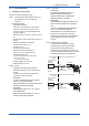
c. Note 6. Installation Instructions [Installation Diagram] + Pressure − SUPPLY Transmitter + − Transmitter + − Transmitter The transmitters with option code /KN26 for potentially explosive atmospheres: • Applicable Standard: EN 60079-0:2009/EN 60079-0:2012, EN 60079-11:2012 • Type of Protection and Marking Code: II 3G Ex ic IIC T4 Gc • Ambient Temperature: –30* to +60°C * –15°C when /HE is specified.
2-6 <2. Handling Cautions> (4) Operation Note 4. Specific Conditions of Use WARNING WARNING • Electrostatic charge may cause an explosion hazard. Avoid any actions that cause the gerenation of eletrostatic charge, such as rubbing with a dry cloth on coating face of the product. • When the lightning protector option is specified, the apparatus is not capable of withstanding the 500V insulation test required by EN60079-11. This must be taken into account when installing the apparatus.
<2. Handling Cautions> STYLE: Style code. SUFFIX: Specified suffix code. SUPPLY: Supply voltage. OUTPUT: Output signal. MWP: Maximum working pressure. CAL RNG: Specified calibration range. NO.: Serial number and year of production*1. TOKYO 180-8750 JAPAN: The manufacturer name and the address*2. *1: The first digit in the final three numbers of the serial number appearing after “NO.” on the name plate indicates the year of production.
3.1 About PROFIBUS PA Outline PROFIBUS PA is a widely used bi-directional digital communication protocol that enables the implementation of technologically advanced process control systems. The DPharp EJX/EJA Series PROFIBUS PA communication type meets the specifications of PROFIBUS Nutzerorganisation e.V. and is interoperable with devices from Yokogawa and other manufacturers. 3.2 Internal Structure of DPharp 3.2.1 Function Block 3.
4. 4-1 <4. Getting Started> Getting Started PROFIBUS PA is fully dependent upon digital communication protocol and differs in operation from conventional 4 to 20 mA transmission. HMI • DP/PA Couplers: PROFIBUS PA requires DP/PA couplers which convert the RS-485 signals to the IEC 61158-2 signal level and power the field devices via the PROFIBUS PA. • Cable: Class 2 Master FieldMate (FDT/DTM) PDM (EDD), etc. Refer to Table 4.1. Class 1 Master I/O CARD, PLC, etc. Table 4.
4.2 Bus Power ON 4.3 Turn on the power of the host and the bus. For models with the integral indicator code “E”, the display shows all segments in the LCD and then changes to the displays shown below sequentially. P SP T F All segments display P SP 4-2 <4. Getting Started> T F P SP T SP T Software Revision, Device Revision and Ident Number can be confirmed by following procedure. (1) Software Revision (a) Confirmation by the name plate Software Revision is marked on the name plate.
4-3 <4. Getting Started> (3) Ident Number 4.4 Refer to section 4.5 for explanation of Ident Number. To activate PROFIBUS PA, the following bus parameters must be set for the master. (a) Confirmation by the name plate Device specific Ident Number and Profile Ident number is marked on the name plate. Profile Ident Number is inside [ ]. (9700 to 02(9720), 9740 to 42(9742)) Refer to Figure 4.3. (b) Confirmation from integral indicator (When the integral indicator code “E”) Please refer to section 4.2.
4.5 Integration of GSD file and IDENT Number The GSD file and Ident number are necessary for PROFIBUS communication. Before starting communication, the device must be specified by the GSD file in the host system and the Ident number of the device. The PROFIBUS device has a profile Ident number and a device-specific Ident number. There are GSD files which correspond to each number. The profile GSD file is a general-purpose file which is defined by the kind and number of function blocks of the device.
5-1 <5. Parameter Setting> 5. Parameter Setting 5.1 Easy Setup 5.1.2 Pressure Range (Scale In) and Pressure Unit IMPORTANT Sensor Transducer Block Target Mode need to be changed to Out of Service (O/S) before changing range values and pressure unit. After setting and sending data with the configuration tool, wait 30 seconds before turning off the transmitter. If it is turned off too soon, the setting will not be stored in the transmitter.
<5. Parameter Setting> 5.1.3 Output Mode (Characterization Type) The Output Mode (Characterization Type) is set as specified in the order when the instrument is shipped. Follow the procedure below to change the Output Mode. Sensor Transducer Block Target Mode need to be changed to Out of Service (O/S) before changing Output Mode(Characterization Type).
5.2.1 Pressure Calibration (1) Zero Point Adjustment DPharp span: 0 to 25.00 kPa Actual level: 13.50 kPa Transmitter output: 13.83 kPa Zero Point Adjustment can be performed in several ways. Choose the optimum method in accordance with the circumstances specified to the application employed. 25.00 kPa Actual level 13.50 kPa a.
a. Auto Adjustment Applying reference pressure of 0% and 100% of the measurement range to the transmitter, adjust the lower and upper points automatically. • Procedure to call up the display DTM Calibration → Pressure Calibration → Calibration → EDD [Menu] → Device → Sensor Calibration → Pressure Calibration → Calibration → → Lower Calibration Auto adjustment for 0% point Point → Upper Calibration Auto adjustment for 100% point Point b.
(4) Reset Adjustment to Factory Setting The Clear Calibration method can reset the adjustment to the initial calibrated values that were set. The amount of the adjustment performed with the external zero-adjustment screw is returned the initial setting as well. Low cut: 20.
5.3.3 Signal Characterizer Below is the example of performing the signal characterizer as shown in Figure 5.2. Target Mode of Sensor Transducer Block need to be changed to Out of Service (O/S) before setting linearization table. In order to use signal characterizer, “User defined (table)” must be chosen for Characterization Type. Refer to subsection 5.1.3 for changing Characterization Type. Y 100% <2>Enter Lower and Upper Scale In / Out value. Refer to subsection 5.1.2 and 5.3.2 for procedure.
<5>To confirm entered coordinate. • Procedure to call up the display DTM EDD [Device] → Configuration → Characterization → Table Data [Device] → Characterization → Linearization Table 5.3.4 Calculate Coefficient (For flow rate calculation) Calculate Coefficient is constant mainly for calculation of flow rate output signal. Follow below procedure to set the Calculate Coefficient. Sensor Transducer Block Target Mode needs to be changed to Out of Service (O/S) before enters Calculate Coefficient.
Table 5.3 # 1 2 3 4 5 6 7 8 <5. Parameter Setting> 5-8 Symbols Symbol Nc Kfactor C ε β d ρb ρnorm Description Unit convert factor Basic flow Calculation factor Discharge Coefficient Expansion Factor Diameter Ratio Diameter of orifice Base Density on Tb, SPb Condition Density on Normal, Standard condition Example 1: Calculation of Nc (1) When flow unit is changed. Nc= (Kg/s) /(Mass Flow unit in use) Table 5.
5-9 <5. Parameter Setting> Table 5.6 Flow Parameter of Example Description Value Symbol C 0.6043 Discharge coefficient Orifice Corner Taps [ISO5167-1 1991] ReD 1×10⁶ ε 0.984 Expansion factor β=0.6, ∆ρ=50,000 Pa, SP=1,000,000 Pa abs, κ=1.399502 β 0.6 Diameter ratio d 0.03162 m Bore of orifice D 0.0527 m Pipe diameter ρb 1.250380 kg/m3 Base Density on Tb, SPb Condition (NITROGEN 101,325 Pa abs 273.15 K) 0.7853982 /4 Unit convert factor when DP unit is kPa 31.
5.4 <5. Parameter Setting> Output Signal Setup 5.4.1 Fail Safe Mode Fail Safe Mode defines the Output Value and Status (Quality) when status of input signal to AI function block or Totalizer function block is BAD.
5.5 <5. Parameter Setting> 5-11 Local Display 5.5.1 Procedure to Set the Integral Indicator Select from Parameter Displays (1-4) (Display Selection) Specify parameters to be displayed (Parameter Selection) Specify whether DISPLAY1, DISPLAY2, DISPLAY3, or DISPLAY4 should be displayed. Select parameters to be displayed. Select items to be displayed in the lower text field (Information Selection) Specify whether tag, parameter, unit, or status should be displayed.
5-12 <5. Parameter Setting> a. Display Selection e. Unit Selection A cycle of up to four displays can be shown by assigning variables to the parameters at Display Selection. Select whether unit to be displayed in the lower text field should be automatically selected or customized by user in parameter Unit Selection. Select “Auto” if you want to have unit chosen from specified units and “Custom” for engineering unit which you can input freely.
<5. Parameter Setting> 5-13 h. Bar Graph ON/OFF setting of Bar Graph in upper field of integral indicator can be performed by Bar Graph parameter. • Procedure to call up the display DTM, EDD → Enable → Disable Local Display → Bar Graph → Enable to indicate bar graph Disable to indicate bar graph i. Display Cycle Displaying period can be set from Display Cycle parameter. • Procedure to call up the display DTM, EDD → Recommend → 1-10 Local Display → Display Cycle → Display cycle: 2.
6. 6.1 6-1 <6. Explanation of Basic Items> Explanation of Basic Items Outline 6.2 This chapter describes brief explanation of the SENSOR transducer block, the LCD transducer block, the AI function block, and the Totalizer function block. Actual mode Many parameters require a change of the mode of the function block to O/S (Out of Service) when their data is changed. To change the mode of the function block, its Target Mode (TARGET_MODE) needs to be changed.
6.2.2 Target Mode The Block modes permitted for the SENSOR transducer block are Automatic (Auto) and Out of Service (O/S). The mode must be set to Auto under normal operating conditions, and to O/S when making changes to an important parameter. For parameters that can only be changed in the Auto and O/S modes, refer to the parameter list for the SENSOR Transducer block. 6.2.
<6. Explanation of Basic Items> Component name Bar graph Center field for numerical values Lower text field Title field Auxiliary characters 6-3 Contents Shows the value displayed in the center field for numerical values scaled in terms of percentage. Presents values of inputs and outputs. While the alarm is on, the alarm number alternates with the displayed value here. Displays tag, parameter name, unit, and signal status. While the alarm is on, the alarm contents alternate.
6-4 <6. Explanation of Basic Items> 6.3.
Index 1358 1359 1360 1361 1362 1363 1364 1365 1366 1371 1372 1373 1374 1448 1449 1450 1451 1452 1453 1454 1455 1456 1457 1458 1459 1460 1461 1462 1479 1480 1481 1482 1483 1484 1485 1486 1487 1488 1489 1490 1491 1492 1493 1494 1495 1496 1497 1498 1499 1500 1501 1502 1503 1504 1505 6-5 <6. Explanation of Basic Items> Unit ft3/h ft3/d ft3/min std. ft3/h std.
6.4 6-6 <6. Explanation of Basic Items> AI Function Block The AI function block is a unit of the software. During execution, it incorporates data from the SENSOR transducer block. After execution, it updates analog outputs and processes newly generated alarms. AI function blocks can provide a discrete output which shows the status of LO, LO_LO, HI, or HI_HI. In terms of function, there is no difference between the three AI function blocks provided in DPharp. 6.4.
6.4.2 Target Mode The Target modes permitted for the AI function block are Automatic (Auto), Manual (Man), and Out of Service (O/S). When the Target mode of PB (Physical Block) is Out of Service (O/S), Actual is Out of Service (O/S) even if Automatic (Auto) or Manual (Man) is written to Target. 6.4.
6-8 <6. Explanation of Basic Items> 6.5.3 Totalizer Value Set (SET_TOT) 6.5.5 Fail Safe Mode (FAIL_TOT) Reset of the internal value of the function block algorithm to 0 or set this value to which configured in Preset Value (PRESET_VALUE). This parameter affects the current totalized value immediately. This function is level sensitive. While this is set to Reset or Preset, the status of the totalized value shall be UNCERTAIN-initial value.
7. <7. In-Process Operation> In-Process Operation This chapter describes the procedure performed when changing the operation of the function block of the transmitter in process. 7.1 Mode Transition When the function block mode is changed to Out_ Of_Service, the function block pauses. When the function block mode is changed to Manual, the function block suspends updating of output values. In this case alone, it is possible to write a value to the OUT parameter of the block for output. 7.
7-2 <7. In-Process Operation> 7.2.3 Alarm Mask Function Table 7.1 shows the parameters related to the masking of alarms. Users can mask DIAGNOSIS_EXTENSION by setting the Diagnosis Mask Extension RW (DIAGNOSIS_MASK_ EXTENSION_RW) parameter. DIAGNOSIS_ EXTENSION displays the results of masking. For details of DIAGNOSIS_EXTENSION, see Table 8.3. The DIAGNOSIS_MASK and DIAGNOSIS_MASK_ EXTENSION are a read-only parameter to display bits which are supported by the device.
7-3 <7. In-Process Operation> 7.3.1 Sensor Transducer Block 7.3.2 AI Function Blocks It is necessary to set parameters as shown in Table 7.2 when the simulation function is used. When SIMULATE MODE in SENSOR Transducer block described at Table 7.2 is set to “1: Pressure Value”, the sensor transducer block uses the simulation value instead of the pressure value “SECONDARY_VALUE_1” before carrying out scaling and linearization.
7.4 Write lock (Write-protect) function 7.5 The transmitter is provided with a write lock (writeprotect) function to restrict write operations to blocks and prevent inadvertent writing of parameter data. To enable this function, use the write lock switch (Hard W Lock) or the WRITE_LOCKING (Physical block index 34) (Soft W Lock). The CPU assembly of the transmitter is provided with a write lock switch (switch 2 in Figure 7.3). Setting switch 2 to On activates the write lock function.
Integral indicator Note 1: Use a thin bar which has a blunt tip, e.g., a hexagonal wrench, to press the Local operation switch. Note 2: The switch is located in either lower right or lower left portion of the LCD indicator. Local operation switch (Push-button) Figure 7.5 F0705.
8. 8.1 <8. Diagnostic Information> 8-1 Diagnostic Information Device Status Diagnostic information and failures are indicated by using parameter Diagnosis and Diagnosis Extension in the Physical Block. DIAGNOSIS has Classic DIAGNOSIS and Condensed DIAGNOSIS. Classic DIAGNOSIS is a conventional alarm and does not support the NAMUR NE107. Condensed DIAGNOSIS is an alarm which was added to PA Profile 3.01 or later and supports the NAMUR NE107. For switching the two statuses, see subsection 7.2.2.
Table 8.1 Octet Bit 1 2 3 Description 4 DIA_COLDSTART *1 Restart (cold startup) carried out. 5 DIA_ MAINTENANCE *2 reserved *2 IDENT_NUMBER_ VIOLATION *2 0 2 3 *1: *2: DIAGNOSIS Mnemonic Reserved *2 Reserved for use within the PNO Reserved *2 Reserved for use within the PNO DIA_WARMSTART*1 New start-up (warm startup) carried out. 1 4 Contents of Condensed DIAGNOSIS 0-7 0-3 3 6 7 4-7 0-6 7 8-2 <8.
Table 8.2 <8.
Table 8.3 Contents of DIAGNOSIS_EXTENSION Octet Bit Category 1 2 0 1 2 3 4 5 6 7 2 Pressure Sensor Failure (AL.01) Capsule Temp Sensor Failure (AL.01) Capsule EEPROM Failure (AL.01) AMP Temp Sensor Failure (AL.02) AMP EEPROM Failure (AL.02) CPU Board Failure 3,4 (AL.02) CPU Board Failure 5 (AL.02) CPU Board Failure 1 (AL.02) Process Alarm Diff Pressure Outside Range Limit (AL.10) 4 5 0 1 2 4 4 5 1 4 5 6 7 *1: Display Message System Alarm 3 3 8-4 <8.
8.2 8-5 <8. Diagnostic Information> Status of Each Parameter in Failure Mode Following tables summarize the value of parameters when LCD display indicates an Alarm. Table 8.4 ALARM Display Action of each parameters in failure mode related Sensor Transducer block (Condensed status) Cause of Alarm AL.01 CAP. ERR Pressure Sensor problem Capsule Temperature Sensor problem Capsule memory problem AL.02 Amplifier AMP. Temperature ERR Sensor problem Amplifier memory problem Amplifier problem AL.
ALARM Display AL.40 PB O/S AL.41 STB O/S AL.43 AI O/S AL.44 AI O/S AL.45 AI O/S AL.72 TOT O/S AL.50 P.SDEV P.ZDEV AL.51 SP.SDEV SP.ZDEV AL.79 LCD. RNG AL.90 AI SIM AL.91 AI SIM AL.
ALARM Display Cause of Alarm AL.93 AI MAN AL.94 AI MAN AL.95 AI MAN AL.96 STB.SIM AI1 block is MAN mode AI2 block is MAN mode AI3 block is MAN mode Simulation function of Sensor TB is active AL.97 PB SIM AL.72 TOT MAN AL.60 STB. CFG 8-7 <8.
Table 8.5 ALARM Display Action of each parameters in failure mode related Sensor Transducer block (Classic status) Cause of Alarm AL.01 CAP. ERR Pressure Sensor problem Capsule Temperature Sensor problem Capsule memory problem AL.02 Amplifier AMP. Temperature ERR Sensor problem Amplifier memory problem Amplifier problem AL.10 Input Pressure PRESS is outside measurement range limit of capsule" AL.11 Static ST.PRSS Pressure exceeds limit AL.12 CAP. TMP Capsule Temerature is out of range AL.13 AMP.
8-9 <8. Diagnostic Information> SENSOR Transducer block ALARM Display AL.40 PB O/S AL.41 STB O/S AL.43 AI O/S AL.44 AI O/S AL.45 AI O/S AL.72 TOT O/S AL.50 P.SDEV P.ZDEV AL.51 SP.SDEV SP.ZDEV AL.79 LCD. RNG AL.90 AI SIM AL.91 AI SIM AL.92 AI SIM AL.93 AI MAN AL.94 AI MAN AL.95 AI MAN AL.96 STB.SIM AL.97 PB SIM AL.72 TOT MAN AL.60 STB.
Table 8.6 ALARM Display AL.01 CAP. ERR Action of each parameters in failure mode related Function blocks (Condensed status) Cause of Alarm Pressure Sensor problem Capsule Temperature Sensor problem Capsule memory problem AL.02 Amplifier AMP. Temperature ERR Sensor problem Amplifier memory problem Amplifier problem AL.10 Input Pressure PRESS is outside measurement range limit of capsule AL.11 Static Pressure ST.PRSS exceeds limit AL.12 Capsule CAP. Temerature is TMP out of range AL.13 Amplifier AMP.
AI1 Output Value (Channel = Primary Value) FSAFE_TYPE FSAFE_TYPE FSAFE_TYPE =0 =1 =2 AL.40 Physical block BAD: BAD: BAD: PB O/S is O/S mode passivated passivated passivated (diagnostis (diagnostis (diagnostis AL.41 SENSOR alerts inhibited) alerts inhibited) alerts inhibited) STB O/S Transducer Constant Constant Constant block is O/S mode AL.43 AI1 function AI O/S block is O/S mode AL.44 AI2 function GOOD (NC): GOOD (NC): GOOD (NC): AI O/S block is O/S OK OK OK mode AL.
ALARM Display AL.93 AI MAN AL.94 AI MAN AL.95 AI MAN AL.96 STB.SIM AL.97 PB SIM AL.72 TOT MAN AL.60 STB. CFG 8-12 <8.
Table 8.7 ALARM Display AL.01 CAP. ERR Action of each parameters in failure mode related Function blocks (Classic status) Cause of Alarm Pressure Sensor problem Capsule Temperature Sensor problem Capsule memory problem AL.02 Amplifier AMP. Temperature ERR Sensor problem Amplifier memory problem Amplifier problem AL.10 Input Pressure PRESS is outside measurement range limit of capsule AL.11 Static Pressure ST.PRSS exceeds limit AL.12 Capsule CAP. Temerature is TMP out of range AL.13 Amplifier AMP.
ALARM Display AL.40 PB O/S AL.41 STB O/S AL.43 AI O/S AL.44 AI O/S AL.45 AI O/S AL.72 TOT O/S AL.50 P.SDEV P.ZDEV AL.51 SP.SDEV SP.ZDEV AL.79 LCD. RNG AL.90 AI SIM AL.91 AI SIM AL.92 AI SIM AL.93 AI MAN AL.94 AI MAN AL.95 AI MAN AL.96 STB.SIM AL.97 PB SIM AL.72 TOT MAN AL.60 STB. CFG 8-14 <8.
9. 9-1 <9. Parameter Lists> Parameter Lists Note: O/S: MAN: AUTO: —: The Write Mode column contains the modes in which each parameter is write enabled. Write enabled in O/S mode. Write enabled in Man mode and O/S mode. Write enabled in Auto mode, Man mode, and O/S mode. Read only. 9.
Relative Index Index 22 38 23 39 24 40 25 <9. Parameter Lists> Parameter DEVICE_INSTAL_ DATE LOCAL_OP_ENA Write Mode AUTO Initial Value 9-2 Explanation Date of installation of the device.
Relative Index Index 72 73 74 9.2 88 89 90 <9.
Relative Index Index 9-4 <9. Parameter Lists> Parameter Write Mode O/S Unknown Initial Value Explanation 25 41 PROCESS_ CONNECTION_TYPE Index code for the material of the process connection. The coding is in accordance to the Material Codes given in teneral Requirements. Material code for the type of process connection. The index code is manufacturer specific.
Relative Index Index 71 87 72 88 73 74 75 76 77 78 89 90 91 92 93 94 79 95 80 81 9-5 <9.
Relative Index Index 176 177 178 179 180 181 182 183 184 185 186 187 188 189 190 191 9.3 192 193 194 195 196 197 198 199 200 201 202 203 204 205 206 207 <9.
<9.
9.4 <9.
9.5 <9.
10. <10. General Specifications> 10-1 General Specifications 10.1 Standard Specifications For items other than those described below, refer to each User’s Manual. Applicable Model: All DPharp EJX/EJA series. Output: Digital communication signal based on PROFIBUS PA protocol. Supply Voltage: 9 to 32 V DC for general use, flameproof type, intrinsically safe (Ex ic), or nonincendive 9 to 24 V DC for intrinsically safe type Entity model 9 to 17.
<10. General Specifications> 10-2 10.2 Optional Specifications For items other than those described below, refer to each User’s Manual. Item Data configuration at factory Software Damping Description Code CD 10.
A1-1 Appendix 1. List of DTM Menu A1.1 Parameter Table • Process Variables • Pressure Raw Value • Pressure Value • Primary Value • Calculated Value • Static Pressure High Side Value • Static Pressure Low Side Value • Capsule Temperature • Amplifier Temperature • AI1 Output Value • AI2 Output Value • AI3 Output Value • Totalizer Value FA0101.
• Easy Setup • TAG • Descriptor • Message • Installation Date • Sensor Transducer Block • Target Mode • Actual Mode • Pressure unit • Scale In:Lower Value • Scale In:Upper Value • Characterization Type • Analog Input 1 • Target Mode • Actual Mode • Channel • Filter Time Const • Out Scale:Lower Value • Out Scale:Upper Value • Out Scale:Unit • Out Scale:Decimal Point A1-2 FA0104.
• Calibration A1-3
• Input A1-4
• Output A1-5 • Analog Input 1 • Analog Input 2 • Analog Input 3 • Totalizer • Static Revision No.
• Local Display • Static Revision No.
A2-1 Appendix 2. List of PDM (EDD) Menu A2.1 Menu Bar Menu Bar • File C • Device D • View E • Options F • Help G C • Save • Delete • Value comparison... • Export.. • Import.. • Print • Print Preview • Printer Setup • Page Setup • Labeling Fields.. • Rename • Object Properties • Exit D • Communication Path • Download to Device • Upload to PC/PG • Update Diagnostics Status • Set Address...
A2-2
A2-4 5 • Characterization • Characterization • Target Mode • Actual Mode • Characterization Type • Low Flow Cut Off • Linearization • Min Number of Coordinates • Max Number of Coordinates • Number of Coordinates • Operation Mode • Coordinate No. • X Y value couple - X • X Y value couple - Y • Status (Characterization) • Linearization Table • X_1 … X_31 • Y_1 … Y_31 FA0215.
12 • Alarm States A2-6 • Function Block 1 - Analog Input • Function Block 2 - Analog Input • Function Block 3 - Analog Input • Function Block 4 - Totalizer • Overview • Alarm Summary • Upper Limit Alarm • Upper Limit Warning • Lower Limit Warning • Lower Limit Alarm 12-1 12-1 12-1 12-1 FA0222.
A2-7 A2.2 Parameter Table • Easy Setup • TAG • Descriptor • Message • Installation Date • Sensor Transducer Block • Function Block 1 - Analog Input 1 • Target Mode • Actual Mode • Characterization Type • Measuring Range - Scale In • Pressure Unit • Lower Value • Upper Value • Target Mode • Actual Mode • Channel • Filter Time Const • Output scale • Lower Value • Upper Value • Unit • Decimal Point FA0202.
• Input A2-8 • Sensor Transducer Block • Static Revision No.
• Output A2-9
• Sensor Calibration • Pressure Calibration • Lower Calibration Point • Upper Calibration Point • Calibration Span Min • Lower Calibration Deviation • Upper Calibration Deviation • Static Pressure Calibration • SP Lower Calibration Point • SP Upper Calibration Point • SP Calibration Span Min • SP Lower Calibration Deviation • SP Upper Calibration Deviation A2-10 FA0207.
• Target Mode • Physical Block • Target Mode • Actual Mode A2-11 I • Sensor Transducer Block • LCD Transducer Block • Function Block 1 - Analog Input • Function Block 2 - Analog Input I • Function Block 3 - Analog Input • Function Block 4 - Totalizer FA0209.
i Revision Information Title : Manual No.