User’s Manual Diaphragm Sealed Differential Pressure and Pressure Transmitters EJ118 and EJ438 IM 01C25H01-01E IM 01C25H01-01E 9th Edition
i Diaphragm Sealed Differential Pressure and Pressure Transmitters EJ118 and EJ438 IM 01C25H01-01E 9th Edition Contents 1. Introduction................................................................................................ 1-1 Regarding This Manual................................................................................................. 1-1 2. 1.1 Safe Use of This Product ................................................................................. 1-2 1.2 Warranty.....
ii 5. 4.5 Affixing the Teflon Film..................................................................................... 4-5 4.6 Rotating Transmitter Section............................................................................ 4-5 4.7 Changing Integral Indicator Direction............................................................. 4-5 Wiring.......................................................................................................... 5-1 5.1 Wiring Precautions...............
iii 8. General Specifications............................................................................. 8-1 8.1 Standard Specifications.................................................................................... 8-1 8.2 Model and Suffix Codes.................................................................................... 8-5 8.3 Optional Specifications “◊”............................................................................ 8-14 8.4 Dimensions..............................
1. 1-1 <1. Introduction> Introduction Thank you for purchasing the DPharp Differential Pressure and pressure transmitter. Your Pressure Transmitter was precisely calibrated at the factory before shipment. To ensure both safety and efficiency, please read this manual carefully before you operate the instrument. NOTE This manual describes the hardware configurations of the transmitters listed in below.
• The following safety symbols are used in this manual: WARNING Indicates a potentially hazardous situation which, if not avoided, could result in death or serious injury. CAUTION Indicates a potentially hazardous situation which, if not avoided, may result in minor or moderate injury. It may also be used to alert against unsafe practices. IMPORTANT Indicates that operating the hardware or software in this manner may damage it or lead to system failure.
(c) Operation • Wait 5 min. after the power is turned off, before opening the covers. (d) Maintenance • Please carry out only the maintenance procedures described in this manual. If you require further assistance, please contact the nearest Yokogawa office. • Care should be taken to prevent the build up of dust or other materials on the display glass and the name plate. To clean these surfaces, use a soft, dry cloth.
<1. Introduction> 1-4 1.3 ATEX Documentation This is only applicable to the countries in European Union.
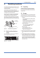
2. 2-1 <2. Handling Cautions> Handling Cautions This chapter provides important information on how to handle the transmitter. Read this carefully before using the transmitter. The transmitters are thoroughly tested at the factory before shipment. When taking delivery of an instrument, visually check them to make sure that no damage occurred during shipment. Also check that all transmitter mounting hardware shown in figure 2.1 is included.
2-2 <2. Handling Cautions> 2.4 Selecting the Installation Location The following precautions must be observed in order to safely operate the transmitter under pressure. The transmitter is designed to withstand severe environmental conditions. However, to ensure that it will provide years of stable and accurate performance, take the following precautions when selecting the installation location. (a) Make sure that there are no leaks in the impulse piping.
<2. Handling Cautions> 2-3 (b) Never apply a voltage exceeding 500 V DC (100 V DC with an internal lightning protector) for the insulation resistance test, nor a voltage exceeding 500 V AC (100 V AC with an internal lightning protector) for the dielectric strength test. (c) Before conducting these tests, disconnect all signal lines from the transmitter terminals. The procedure for conducting these tests is as follows: 2.
IMPORTANT For combined approval types Once a device of multiple approval type is installed, it should not be re-installed using any other approval types. Apply a permanent mark in the check box of the selected approval type on the certification label on the transmitter to distinguish it from unused approval types. IMPORTANT All the blind plugs which accompany the EJX/ EJA-E transmitters upon shipment from the factory are certified by the applicable agency in combination with those transmitters.
<2. Handling Cautions> Note 4. Maintenance and Repair • The instrument modification or parts replacement by other than authorized representative of Yokogawa Electric Corporation is prohibited and will void Factory Mutual Intrinsically safe and Nonincendive Approval. Note 2. Wiring • All wiring shall comply with National Electrical Code ANSI/NFPA70 and Local Electrical Codes. • When installed in Division 1, “FACTORY SEALED, CONDUIT SEAL NOT REQUIRED.
2.9.2 CSA Certification a. CSA Intrinsically Safe Type Caution for CSA Intrinsically safe and nonincendive type. (Following contents refer to “DOC No. ICS013-A13”) Note 1. Model EJX/EJA-E Series differential, gauge, and absolute pressure transmitters with optional code /CS1 are applicable for use in hazardous locations Certificate: 1606623 [For CSA C22.2] • Applicable Standard: C22.2 No.0, C22.2 No.0.4, C22.2 No.25, C22.2 No.94, C22.2 No.157, C22.2 No.213, C22.2 No.61010-1, C22.2 No.
<2. Handling Cautions> • Explosion-proof for Class I, Groups B, C and D. • Dustignition-proof for Class II/III, Groups E, F and G. • Enclosure: NEMA TYPE 4X • Temperature Code: T6...T4 • Ex d IIC T6...T4 • Enclosure: IP66/IP67 • Maximum Process Temperature: 120°C (T4), 100°C (T5), 85°C (T6) • Ambient Temperature: –50* to 75°C (T4), –50* to 80°C (T5), –50* to 75°C (T6) * –15°C when /HE is specified. • Supply Voltage: 42 V dc max. • Output Signal: 4 to 20 mA dc Note 2.
2.9.3 ATEX Certification [Control Drawing] Hazardous Location (1) Technical Data Supply Caution for ATEX Intrinsically safe type. * –15°C when /HE is specified. • Process Temperature (Tp.): 120°C max. • Maximum Surface Temperature for EPL Db: T85°C (Tp.: 80°C) T100°C (Tp.: 100°C) T120°C (Tp.
b. ATEX Flameproof Type Caution for ATEX flameproof type. Note 1. Model EJX/EJA-E Series pressure transmitters with optional code /KF22 for potentially explosive atmospheres: • No. KEMA 07ATEX0109 X • Applicable Standard: EN 60079-0:2009, EN 60079-1:2007, EN 60079-31:2009 • Type of Protection and Marking Code: Ex d IIC T6...
● ATEX Intrinsically Safe Ex ic WARNING Caution for ATEX intrinsically safe Ex ic • Applicable Standard: EN 60079-0:2009/EN 60079-0:2012, EN 60079-11:2012 • Type of Protection and Marking Code: II 3G Ex ic IIC T4 Gc • Ambient Temperature: –30* to +60°C * –15°C when /HE is specified. • Ambient Humidity: 0 to 100% (No condensation) • Maximum Process Temperature: 120°C • IP Code: IP66 • Ambient pollution degree: 2 • Overvoltage category: I Note 1. Electrical Data Ui = 30 V Ci = 27.
2-11 <2. Handling Cautions> (5) Maintenance and Repair WARNING The instrument modification or parts replacement by other than an authorized Representative of Yokogawa Electric Corporation is prohibited and will void the certification. *1: The first digit in the three numbers next to the nine letters of the serial number appearing after “NO.” on the nameplate indicates the year of production.
<2. Handling Cautions> • Installation Requirements Uo ≤ Ui, Io ≤ Ii, Po ≤ Pi, Co ≥ Ci + Ccable, Lo ≥ Li + Lcable Voc ≤ Vmax, Isc ≤ Imax, Ca ≥ Ci + Ccable, La ≥ Li + Lcable Uo, Io, Po, Co, Lo, Voc, Isc, Ca and La are parameters of barrier. Note 3. Installation • In any safety barrier used output current must be limited by a resistor 'R' such that Io=Uo/R. • The safety barrier must be IECEx certified. • Input voltage of the safety barrier must be less than 250 Vrms/Vdc.
2.11 Pressure Equipment Directive (PED) (1) General EJX/EJA-E Series pressure transmitters are categorized as piping under the pressure accessories section of directive 97/23/EC, which corresponds to Article 3, Paragraph 3 of PED, denoted as Sound Engineering Practice (SEP). <2. Handling Cautions> 2-13 (2) Installation Category I "Overvoltage category (Installation category)" describes a number which defines a transient overvoltage condition.
3-1 <3. Component Names> 3. Component Names EJ118 EJ438 Drain/vent plug Transmitter section* Flushing connection ring *See below for details. Cover flange *See below for details. Cover flange Diaphragm seal with flushing connection ring Diaphragm seal (high pressure side) Diaphragm seal Capillary tube Diaphragm seal (low pressure side) Pressure-detector section Figure 3.1 Transmitter section* Pressure-detector section F0301.
4. <4. Installation> 4-1 Installation 4.1 Precautions Before installing the transmitter, read the cautionary notes in Section 2.4, “Selecting the Installation Location.” For additional information on the ambient conditions allowed at the installation location, refer to Subsection 8.1 “Standard Specifications.” IMPORTANT • When welding piping during construction, take care not to allow welding currents to flow through the transmitter. • Do not step on this instrument after installation.
4-2 <4. Installation> IMPORTANT 4.3 Transmitter Mounting Low pressure side Install the sealed diaphragm so that the shank positions downward. High pressure side Minimum liquid level 50mm minimum ■ The transmitter can be mounted on a nominal 50 mm (2-inch) pipe using the mounting bracket supplied, as shown in Figure 4.3. The transmitter can be mounted on either a horizontal or a vertical pipe.
IMPORTANT Low pressure side The transmitter should be installed at least 600 mm below the high pressure (HP) process connection to ensure a positive head pressure of fill fluid. Pay special attention to vacuum applications.
4-4 <4. Installation> 4.4 Mounting the Flushing Connection Ring 4.4.2 Mounting to Process Flange Tighten the bolts to completely close the gap between the ring and the pressure detector section. The mating flange, gasket, stud bolts and nuts are to procured by the customer. 4.4.1 Mounting to Pressure Detector Section The flushing connection ring is mounted to the pressure detector section as shown in Figure 4.6.
4-5 <4. Installation> 4.5 Affixing the Teflon Film The FEP Teflon option includes a teflon film and fluorinated oil. Before mounting the diaphragm seal to the process flange, affix the teflon film as follows: IMPORTANT 1) Position the diaphragm seal so that the diaphragm is in a upward position. 2) Pour the fluorinated oil on the diaphragm and gasket area covering it completely and evenly. Be careful not to scratch the diaphragm or change the its shape.
Wiring IMPORTANT • Lay wiring as far as possible from electrical noise sources such as large capacity transformers, motors, and power supplies. • Remove the electrical connection dust cap before wiring. • All threaded parts must be treated with waterproofing sealant. (A non-hardening silicone group sealant is recommended.) • To prevent noise pickup, do not pass signal and power cables through the same ducts.
5-2 <5. Wiring> 5.3.4 Check Meter Connection (1) General-use Type and Flameproof Type Available only when /AL is not specified. Hazardous Location Connect the check meter to the CHECK + and – terminals. (Use hooks.) Transmitter terminal box Distributor (Power supply unit) PULSE • A 4 to 20 mA DC output signal from the CHECK + and – terminals. Nonhazardous Location SUPP LY CHECKM ALAR Receiver instrument (Note) Use a check meter whose internal resistance is 10 Ω or less.
5-3 <5. Wiring> (2) Flameproof Type 5.5 Grounding Wire cables through a flameproof packing adapter, or use a flameproof metal conduit. Grounding is always required for the proper operation of transmitters. Follow the domestic electrical requirements as regulated in each country. For a transmitter with a built-in lightning protector, grounding should satisfy ground resistance of 10Ω or less. ■ Wiring cable through flameproof packing adapter.
6-1 <6. Operation> 6. Operation 6.1 Preparation for Starting Operation This section describes the operation procedure for the EJ118 as shown in Figure 6.1 when measuring liquid level in a closed tank, and EJ438 as shown in Figure 6.2 when measuring pressure in a tank. (a) Confirm that there is no leak in the connecting part of each diaphragm seal mounting flange. (b) Turn ON power and connect the communicator.
6-2 <6. Operation> Using the integral indicator • If the wiring system is faulty, the display stays blank. • If the transmitter is faulty, an error code is displayed. IMPORTANT Do not turn off the power to the transmitter immediately after performing a zero point adjustment. Powering off within 30 seconds of performing this procedure will return the zero point to its previous setting. NOTE Self-diagnostic error on the integral indicator (Faulty transmitter) F0604.
(2) When you cannot obtain the Low Range Value from the actual measured value of 0%; Adjust the transmitter output to the actual measured value obtained by a digital manometer or a glass gauge. [Example] The measuring range of 50 to 250 kPa; the actual measured value of 130 kPa. Actual measured value= 6-3 <6. Operation> 130–50 x100=40.0% 250–50 (=10.4mA) Turn the screw to match the output signal to the actual measured value. 6.
<6. Operation> When you loosen the drain screw, the accumulated liquid(or gas) will be expelled in the direction of the arrow. Drain screw F0606.ai Figure 6.3 Draining for Flushing Connection Ring 6-4 When pressure is applied to the transmitter, the lowand high-limit values for the measurement range (LRV and URV) can be changed (re-ranged) using the range-setting switch (push-button) located on the optional integral indicator plate and the external zero adjustment screw.
<6. Operation> 6-5 IMPORTANT • Do not turn off the power to the transmitter immediately after completion of the change in the LRV and/or URV setting(s). Note that powering off within thirty seconds after setting will cause a return to the previous settings. • Changing LRV automatically changes URV to the following value.
7. 7-1 <8. Maintenance> Maintenance 7.1 Overview WARNING Since the accumulated process fluid may be toxic or otherwise harmful, take appropriate care to avoid contact with the body or inhalation of vapors when draining condensate or venting gas from the transmitter pressure-detector section and even after dismounting the instrument from the process line for maintenance. Maintenance of the transmitter is easy due to its modular construction.
Table 7.1 Instruments Required for Calibration Name Power supply Load resistor Voltmeter Digital manometer Pressure generator Pressure source 7-2 <8. Maintenance> Yokogawa-recommended Instrument Model SDBT or SDBS distributor Model 2792 standard resistor [250 Ω ±0.005%, 3 W] Load adjustment resistor [100 Ω ±1%, 1 W] Model 2501 A digital multimeter Accuracy (10V DC range): ±(0.002% of rdg + 1 dgt) Model MT220 precision digital manometer 1) For 10 kPa class Accuracy: ±(0.015% of rdg + 0.
7-3 <8. Maintenance> 7.4 Disassembly and Reassembly This section describes procedures for disassembly and reassembly for maintenance and component replacement. Always turn OFF power and shut off and release pressures before disassembly. Use proper tools for all operations. Table 7.2 shows the tools required. Table 7.
■ Mounting the CPU Assembly Output terminal cable 1) Connect the flat cable (with white connector) between the CPU assembly and the capsule. 2) Connect the output terminal cable (with brown connector). Press forward NOTE Slide switch Integral indicator Boss Zeroadjustment screw CPU assembly Bracket (for zero-adjustment screw pin) Zero-adjustment LCD board assembly screw pin Mounting screw Amplifier Cover F0703.ai Figure 7.3 7-4 <8.
7-5 <8. Maintenance> This transmitter is equipped with a self-diagnostic function which will be useful in troubleshooting, and the transmitter equipped with an integral indicator will show an alarm code as a result of selfdiagnosis. See subsection 7.5.3 for the list of alarms. See also each communication manual. 7.5.2 Troubleshooting Flowcharts The following sorts of symptoms indicate that the transmitter may not be operating properly. Example : • There is no output signal.
7-6 <8. Maintenance> Output travels beyond 0% or 100%. Large output error. Connect BRAIN TERMINAL and check self-diagnostics. Connect BRAIN TERMINAL and check self-diagnostics. Does the selfdiagnostic indicate problem location? NO Refer to error message summary in each communication manual to take actions.
7-7 <8. Maintenance> 7.5.3 Alarms and Countermeasures Table 7.3 Indicator None AL. 01 CAP. ERR AL. 02 AMP. ERR AL. 10 PRESS AL. 11 ST. PRSS AL. 12 CAP. TMP AL. 13 AMP. TMP AL. 30 RANGE AL. 31 SP. RNG AL. 35 *1 P. HI AL. 36 *1 P. LO AL. 37 *1 SP. HI AL. 38 *1 SP. LO AL. 39 *1 TMP. HI AL. 40 *1 TMP. LO AL. 50 P. LRV AL. 51 P. URV AL. 52 P. SPN AL. 53 P. ADJ AL. 54 SP. RNG AL. 55 SP. ADJ AL. 60 SC. CFG AL. 79 OV. DISP Alarm Message Summary Cause Sensor problem. Capsule temperature sensor problem.
8. General Specifications 8.1 Standard Specifications Refer to IM 01C25T02-01E for FOUNDATION Fieldbus communication type and IM 01C25T0401EN for PROFIBUS PA communication type for the items marked with “◊”.
Normal Operating Condition Process Temperature Limits See table 8.1. Ambient Temperature Limits –40 to 60°C (–40 to 140°F) –30 to 60°C (–22 to 140°F) with LCD display Ambient Humidity Limits 0 to 100% RH (Selected features may affect limits.) Note: The ambient temperature limits must be within the fill fluid operating temperature range, see table 8.1. Table 8.
Transmitter ambient temperature range (for fill fluid code D) Process temperature for fill fluid code E Process temperature for fill fluid code D Flange max. working pressure Working pressure kPa abs (psi abs) 100 (14.5) Atmospheric pressure 51 (7.4) Transmitter ambient temperature range (for fill fluid code 2)*1 Process temperature for fill fluid code 2 Flange max. working pressure Working pressure kPa abs (psi abs) Atmospheric pressure 100(14.5) 10(1.4) 10 (1.4) 2.7(0.38) 2.7 (0.38) 1(0.
Supply & Load Requirements “◊” (Optional features or approval codes may affect electrical requirements.) With 24 V DC supply, up to a 550 Ω load can be used. See graph below. HART Communication Distance Up to 1.5 km {1 mile} when using multiple twisted pair cables. Communication distance varies depending on type of cable used. External load resistance R (Ω) Use the following formula to determine cable length for specific applications: 65 × 106 (Cf + 10,000) L= – (R × C) C 600 R= E-10.5 0.
Electrical Connections See “Model and Suffix Codes.” Transmitter Mounting 2-inch pipe mounting Wetted Parts Material Diaphragm seal Diaphragm and other wetted parts; Refer to “Model And Suffix Codes.” Flushing connection ring (optional) Ring and Vent / Drain plugs Refer to “Model And Suffix Codes.
<8. General Specifications> 8-6 EJ118 EJ438 I Transmitter body section II Diaphragm seal section Flush type Flange size: 80A, 50A Flange size: 40A Extended type Combination type See Page 8-6 See Page 8-7 • • • See Page 8-8 • • • See Page 8-10 • • • See Page 8-11 • • • See Page 8-13 F0804.ai EJ118 I. Transmitter body section EJ118 F0805-1.ai Model EJX118A EJA118E Output signal Suffix codes Description ......................
8-7 <8. General Specifications> EJ438 I. Transmitter body section EJ438 F0806-1.ai Model Suffix codes EJX438A EJA438E ......................
8-8 <8. General Specifications> II.
<8. General Specifications> 8-9 The “►” marks indicate the most typical selection for each specification. Example: EJX118A-DMSCG-912EN-WA13B1SW00-BA25/ *1: See table 8.3 ‘Gasket contact surface’ on page 8-4. *2: When specified flushing connection ring code 1, 2, A, or B, exclusive gasket is provided for transmitter side. *3: In case of wetted parts material code TW (Tantalum), the process temperature limit is –10 to 200°C. *4: Wetted parts material code TW (Tantalum) cannot be applied.
8-10 <8. General Specifications> II.
8-11 <8. General Specifications> II.
<8. General Specifications> 8-12 *1: *2: See table 8.3 ‘Gasket contact surface’ on page 8-4. Even in case where fill fluid code D (fluorinated oil) is selected, if degrease cleansing treatment or both degrease cleansing and dehydrating treatment for the wetted parts is required, specify option code K1 or K5. *3: The specified capillary length includes the extension length (X2) and the flange thickness (t). *4: Forged version of the material may be used.
8-13 <8. General Specifications> II. Diaphragm seal section (Combination type) ● Process connection size: Low pressure side; 4-inch (100 mm) · · · Extended type High pressue side; 3-inch (80 mm) · · · Flush type EJ118 Y W F0810-1.
8-14 <8. General Specifications> 8.3 Optional Specifications “◊” Item Factory Mutual (FM) Description FM Explosionproof *1 Explosionproof for Class I, Division 1, Groups B, C and D Dust-ignitionproof for Class II/III, Division 1, Groups E, F and G Hazardous (classified) locations, indoors and outdoors (NEMA 4X) FM Intrinsically safe *1*3 Intrinsically Safe for Class I, Division 1, Groups A, B, C and D, Class II, Division 1,Groups E, F and G and Class III, Division 1 Hazardous Locations.
Item Oil-prohibited use Oil-prohibited use with dehydrating treatment Calibration units *6 Teflon film *5 *11 Operating temperature correction *8 Capillary without PVC sheaths Output limits and failure operation *7 Gold-plate *9 Stainless steel tag plate Data configuration at factory *10 Advanced diagnostics *13 For B-Capsule EJX438A, EJA438E For ACapsule *19 EJX118A EJA118E Material certificate Pressure test/Leak test Certificate 8-15 <8.
*6: *7: *8: *9: *10: *11: *12: *13: *14: *15: *16: *17: *18: *19: <8. General Specifications> 8-16 The unit of MWP (Max. working pressure) on the name plate of a housing is the same unit as specified by option code D1, D3, and D4. Applicable for output signal code D, E and J. The hardware error indicates faulty amplifier or capsule. Specify the process operating temperature for zero correction. Example: Zero correction by process temperature 90°C.
8-17 <8. General Specifications> 8.4 Dimensions Transmitter body section Unit: mm (Approx.: inch) Conduit connection 95(3.74) 54 (2.13) Electrical connection for code 5 and 9. 39 12 (0.47) (1.54) Terminal side Ground terminal 124(4.88) High pressure side (1.85) 83(3.27) 47 315(12.40) Zero adjustment 110(4.33) Shrouding Mounting bracket (flat-type, optional) 129(5.08) 89(3.50) Integral indicator (optional) 175(6.89) 6 (0.24) 137(5.39) ø78(3.
8-18 <8. General Specifications> < Diaphragm seal section > Flush type Unit: mm (Approx.: inch) • No ring (flushing connection ring code 0) • With ring (flushing connection ring code 1, 2, 3, 4, A, B, C and D) Diaphragm seal 112*6 øC øD øg Drain/vent plug Extended type Capillary length *1: When wetted parts material code UW (titanium), value is 34 (1.34) *2: Indicates inside diameter of gasket contact surface *3: In case where process flange material is JIS S25C, value of f is 0.
8-19 <8. General Specifications> Unit: mm (Approx.: inch) Process flange size: 4 inch (100 mm) Code J1 J2 J4 A1 A2 P1 P2 D2 D4 Flange rating øD øC øg JIS 10K 210(8.27) 175(6.89) 155(6.10) JIS 20K 225(8.86) 185(7.28) 155(6.10) JIS 40K 250(9.84) 205(8.07) 155(6.10) ANSI class 150 228.6(9.00) 190.5(7.50) 155(6.10) ANSI class 300 254(10.00) 200.2(7.88) 155(6.10) JPI class 150 229(9.02) 190.5(7.50) 155(6.10) JPI class 300 254(10.0) 200.2(7.88) 155(6.10) DIN PN10/16 220(8.66) 180(7.09) 155(6.
Terminal Wiring Terminal Configuration Communication terminals (BT200 etc.) connection hook SUPPLY + SUPPLY – 8-20 <8.
i Revision Information Title : Diaphragm Sealed Differential Pressure and Pressure Transmitters EJ118 and EJ438 Manual No. : IM 01C25H01-01E Edition 1st 2nd Date Oct. 2004 Feb. 2005 3rd July 2006 Page — 2-5 2-6 8-6, 8-7 8-10 2-3 2-3 to 2-9 2-6 2-9 2-10 2-11 4th Feb. 2008 5th Aug. 2009 6th Apr.
ii Edition 7th Date Mar. 2012 8th June 2012 9th June 2013 Page 2-3 8-4 8-5 to 8-6 — 1-1 2.3 to 2.12 2-7 to 2-10 9.1 to end — 2-3 2-6, 2-7 2-8 to 2-11 2.9 8.1 8.2 2.9 2.9.3 2.9.2 2.9.3 4-3 8-2 8-6 to 8-7 8-8 to 8-13 8-14 4.3 8.1 8.2 8-17 8.4 8.3 Revised Item • Add note for blind plugs. • Change description for a plate material. • Add amplifier housing code 3. • Add EJA-E series. • Add Note. Add model name of EJA-E series. • Delete /V1U. • Delete /KS2, /KF21, and /KU21.