
User Manual


<8. General Specications>
8-10
IM 01C25H01-01E
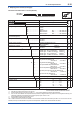
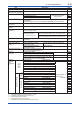
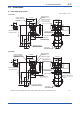
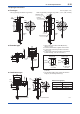
II. Diaphragm seal section (Flush type)
● Process connection size: 1 1/2-inch (40 mm)
F0808-1.ai
EJ118
EJ438
W 8
Model Sufx codes Description
EJ118
EJ438
EJ118
EJ438
Transmitter body section (I)
Process connection style
-W
Flush type
Flange rating
J1
J2
J4
A1
A2
A4
JIS 10K
JIS 20K
JIS 40K
ANSI class 150
P1 . . . . . . . . .
JPI class 150
ANSI class 300
P2 . . . . . . . . .
JPI class 300
ANSI class 600
P4 . . . . . . . . .
JPI class 600
Process connection size
(Process ange size)
8
1 1/2-inch (40 mm)
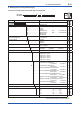
Flange material
►
A
B
C
JIS S25C
304 SST
*5
316 SST
*5
Gasket contact surface
*1
1
2
Serration (for ANSI ange only)
Flat (no serration)
Wetted parts material
SW
[Diaphragm] [Others]
316L SST
#
316L SST
#
Flushing connection ring
*2
3
4
C
D
[Ring] [Drain/Vent plugs] [Material]
Reducer type R 1/4 connections
*4
316 SST
#
Reducer type 1/4 NPT connections 316 SST
#
Reducer type R 1/4 connections
*4
316 SST
#
Reducer type 1/4 NPT connections 316 SST
#
—
—
—
—
Extension
0
None
Fill uid
►
-A
-B
-D
-E
-1
-4
[Process temp.] [Ambient temp.]
For general use (Silicone oil)
–10 to 250°C –10 to 60°C
For general use (Silicone oil)
–30 to 180°C –15 to 60°C
For oil-prohibited use (uorinated oil)
*3
–20 to 120°C –10 to 60°C
For low temperature use (ethylene glycol)
–50 to 100°C –40 to 60°C
High temp. and high vacuum use (Silicone oil)
–10 to 250°C –10 to 50°C
High vacuum use (Silicone oil)
–10 to 100°C –10 to 50°C
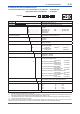
Capillary connection
A
Side of diaphragm seal unit
—
2
Always 2
Capillary length
1
2
3
4
5
1 m 6 . . . . . . . . . 6 m
2 m 7 . . . . . . . . . 7 m
3 m 8 . . . . . . . . . 8 m
4 m 9 . . . . . . . . . 9 m
5 m A . . . . . . . . . 10 m
Option codes
/
Optional specication
The “►” marks indicate the most typical selection for each specication. Example: EJX118A-DMSCG-912EN-WA18B1SW40-BA25/
EJX438A-DAS2G-912EN-WA18B1SWD0-BA25/
*1: See table 8.2 ‘Gasket contact surface’ on page 8-4.
*2: When specied ushing connection ring code 3, 4, C, or D, exclusive gasket is provided for transmitter side.
*3: Even in case where fill fluid code D (fluorinated oil) is selected, if degrease cleansing treatment or both degrease cleansing and
dehydrating treatment for the wetted parts is required, specify option code K1 or K5.
*4: Not applicable for gasket contact surface code 1.
*5: Forged version of the material may be used.
The “#” marks indicate the construction materials conform to NACE material recommendations per MR01-75. For the use of 316 SST
material, there may be certain limitations for pressure and temperature. Please refer to NACE standards for details.