User’s Manual EJX210B Flange Mounted Differential Pressure Transmitter IM 01C27C01-01EN IM 01C27C01-01EN Yokogawa Electric Corporation 8th Edition
i EJX210B Flange Mounted Differential Pressure Transmitter IM 01C27C01-01EN 8th Edition Contents 1. 2. Introduction................................................................................................ 1-1 1.1 Safe Use of This Product ................................................................................. 1-2 1.2 Radio Wave......................................................................................................... 1-3 1.3 Warranty....................................
ii 4.6 4.7 5. 5.2 6.2 8. Mounting to Pressure Detector Section.............................................. 4-3 4.6.2 Mounting to Process Flange............................................................... 4-3 Affixing the Teflon Film..................................................................................... 4-4 Impulse Piping Installation Precautions......................................................... 5-1 5.1.1 Connecting Impulse Piping to the Transmitter........................
iii 8.4 9. 8.3.8 Integral Indicator Setup..................................................................... 8-19 8.3.9 Unit for Displayed Temperature........................................................ 8-20 8.3.10 Unit for Displayed Static Pressure.................................................... 8-20 8.3.11 Zero Point Adjustment and Span Adjustment................................... 8-20 8.3.12 Software Write Protection.................................................................
1. 1-1 <1. Introduction> Introduction Thank you for purchasing the DPharp EJX Differential Pressure transmitter. • Yokogawa assumes no responsibilities for this product except as stated in the warranty. Your EJX Pressure Transmitter was precisely calibrated at the factory before shipment. To ensure both safety and efficiency, please read this manual carefully before you operate the instrument.
1.1 Safe Use of This Product For the safety of the operator and to protect the instrument and the system, please be sure to follow this manual’s safety instructions when handling this instrument. If these instructions are not heeded, the protection provided by this instrument may be impaired. In this case, Yokogawa cannot guarantee that the instrument can be safely operated.
1.2 Radio Wave IMPORTANT - - - 1.3 This instrument is equipped with a wireless module which is designated as a certification of construction type as a wireless facility for 2.4 GHz band low-power data communication system of the Radio Act. Refer to 2.12 “Regulatory Compliance for Radio and Telecommunication” for detail.
1.5 <1. Introduction> 1-4 ATEX Documentation This is only applicable to the countries in European Union.
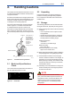
2. 2-1 <2. Handling Cautions> Handling Cautions This chapter provides important information on how to handle the transmitter. Read this carefully before using the transmitter. EJX Series transmitters are thoroughly tested at the factory before shipment. When taking delivery of an instrument, visually check them to make sure that no damage occurred during shipment. Also check that all transmitter mounting hardware shown in figure 2.1 is included.
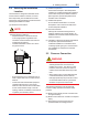
2.4 2-2 <2. Handling Cautions> Selecting the Installation Location The transmitter is designed to withstand severe environmental conditions. However, to ensure that it will provide years of stable and accurate performance, take the following precautions when selecting the installation location.
2.6 Restrictions on Use of Radio Transceivers IMPORTANT Although the transmitter has been designed to resist high frequency electrical noise, if a radio transceiver is used near the transmitter or its external wiring, the transmitter may be affected by high frequency noise pickup. To test this, start out from a distance of several meters and slowly approach the transmitter with the transceiver while observing the measurement loop for noise effects.
2.8 Installation of an ExplosionProtected Instrument If a customer makes a repair or modification to an intrinsically safe instrument and the instrument is not restored to its original condition, its intrinsically safe construction may be compromised and the instrument may be hazardous to operate. Please contact Yokogawa before making any repair or modification to an instrument. CAUTION This instrument has been tested and certified as being intrinsically safe.
Note 4. Battery Pack USE ONLY BATTERY PACK YOKOGAWA F9915MA OR F9915NS. Note 5. Special Conditions for safe use POTENTIAL ELECTROSTATIC CHARGING HAZARD-SECURE DISTANCE OF 100MM FROM ANTENNA. DO NOT OPEN WHEN CL II, III, DIV 1,2 ATMOSPHERE IS PRESENT. 2.8.2 CSA Certification Caution for CSA Intrinsically safe type. (Following contents refer to “DOC No. ICS030”) Note 1.
2-6 <2. Handling Cautions> Note 2. Installation • Installation should be in accordance with local installation requirements. (Refer to the Control Drawing) (2) Operation WARNING Take care not to generate mechanical sparking when access to the instrument and peripheral devices in a hazardous location.
2-7 <2. Handling Cautions> 2.8.4 IECEx Certification Caution for IECEx Intrinsically safe type. Note 1. Model EJX Series pressure transmitters with optional code /SS27 for potentially explosive atmospheres: • No. IECEx KEM 10.0074X • Applicable Standard: IEC 60079-0:2011, IEC 60079-11:2011, IEC 60079-26:2006 • Type of Protection and Marking code: Ex ia IIC T4 Ga • Ambient Temperature: –50°C to 70°C • Process Temperature (Tp.): 120°C max. • Enclosure: IP66/IP67 Note 2.
(2) Technical Data Article 3, Paragraph 3 of PED, denoted as Sound Engineering Practice (SEP). (3) Operation CAUTION • The temperature and pressure of fluid should be maintained at levels that are consistent with normal operating conditions. • The ambient temperature should be maintained at a level that is consistent with normal operating conditions. • Please take care to prevent water hammer and the like from inducing excessive pressures in pipes and valves.
NOTE This equipment has been tested and found to comply with the limits for a Class A digital device, pursuant to part 15 of the FCC Rules. These limits are designed to provide reasonable protection against harmful interference when the equipment is operated in a commercial environment. This equipment generates, uses, and can radiate radio frequency energy and, if not installed and used in accordance with the instruction manual, may cause harmful interference to radio communications.
3. 3-1 <3.
4. 4.1 <4. Installation> Installation Precautions Before installing the transmitter, read the cautionary notes in Section 2.4, “Selecting the Installation Location.” For additional information on the ambient conditions allowed at the installation location, refer to Subsection 11.1 “Standard Specifications.” NOTE To connect this transmitter to the field wireless network, the information on connecting to field wireless devices needs to be set beforehand. Refer to 7.
4-2 <4. Installation> 4.5 IMPORTANT Do not rotate the transmitter section more than the above limit. Transmitter section Rotate 180° segments Pressure-detector section Changing the direction of the antenna Adjust the direction of the antenna to be in the upright position. To change the installation angle, follow the procedure below. 1) Loosen the two mounting screws at the bottom of the antenna by using a 2.5 mm Allen wrench (see Figure 4.3).
4.6 4-3 <4. Installation> Mounting the Flushing Connection Ring 4.6.2 Mounting to Process Flange Tighten the bolts to completely close the gap between the ring and the pressure detector section. 4.6.1 Mounting to Pressure Detector Section The flushing connection ring is mounted to high pressure side pressure detector section as shown in Figure 4.5. At the factory shipment, the flushing connection ring is already assembled and attached to high pressure side process detector section.
4.7 <4. Installation> 4-4 Affixing the Teflon Film The FEP Teflon option includes a teflon film and fluorinated oil. Before mounting the transmitter to the process flange, affix the teflon film as follows: IMPORTANT 1) Position the diaphragm so that the diaphragm is in a upward position. 2) Pour the fluorinated oil on the diaphragm and gasket area covering it completely and evenly. Be careful not to scratch the diaphragm or change the its shape.
5. 5.1 5-1 <5. Installing Impulse Piping> Installing Impulse Piping Impulse Piping Installation Precautions The impulse piping that connects the process outputs to the transmitter must convey the process pressure accurately. If, for example, gas collects in a liquid-filled impulse line, or the drain of a gas-filled impulse line becomes plugged, it will not convey the pressure accurately.
5.2 <5. Installing Impulse Piping> 5-2 Impulse Piping Connection Examples Figure 5.2 shows examples of typical impulse piping connections. Before connecting the transmitter to the process, study the transmitter installation location, the process piping layout, and the characteristics of the process fluid (corrosiveness, toxicity, flammability, etc.), etc. and make appropriate changes and additions to the connection configurations.
6. 6.1 <6. Wiring> 6-1 Wiring Mounting Antenna and Wiring For Amplifier housing code 8 and 9, an antenna is not attached to the transmitter. The following provides the instructions for mounting the antenna and installing the remote antenna and wiring using antenna extension cable. IMPORTANT The antenna connector is covered with a cap at the time of delivery. Keep the cap attached until the installation of the antenna or antenna cables to protect the inside connection part.
6-2 <6. Wiring> 6.1.2 Mounting External Antenna and Wiring Antenna Extension Cable 6.1.2.1 Mounting of External Antenna Mount the external antenna at the proper location according to the wireless environment described in 2.4 Selecting the Installation Location. The mounting to the pipe such as 50 mm (2-inch) pipe needs to secure the enough strength to endure a strong wind, vibration and so on. The antenna must be mounted vertically.
6-3 <6. Wiring> Antenna Antenna extension cable 2: 10 m Antenna Protect by self-bonding tape Arrester Grounding cable Antenna extension cable 1: 3 m Protect by self-bonding tape Antenna extension cable 1: 3 m Transmitter body Transmitter body F0604.ai Figure 6.4 Wiring the antenna extension cable CAUTION Use the dedicated antenna extension cable provided by Yokogawa as accessories for the transmitters.
<6. Wiring> 6-4 6.1.2.3 Mounting of Arrester and Wiring 6.2 Mount an arrester between the extension cables and connect the grounding cable to the grounding terminal of the arrester as required. When using the antenna extension cable with an arrestor, Class C grounding with the grounding resistance of 10 Ω is required. Always ground the transmitter case in accordance with national and local electrical codes.
7-1 <7. Operation> 7. Operation 7.1 Preparation for Starting Operation Open Tank The EJX210B flange mounted differential pressure transmitter measures the levels or densities of liquids. This section describes the operation procedure for the EJX210B as shown in Figure 7.1 when measuring a liquid level in an open tank. NOTE It is required to set security and network information to enable the transmitter to be connected to the Field Wireless Network. For more details, refer to section 7.
• Measurement range (measurement lower/ upper limit, unit). 7.2 7-2 <7. Operation> Zero Point Adjustment After completing preparations for operating the transmitter, adjust the zero point. There are two zero point adjusting ways. IMPORTANT Do not turn off the power to the transmitter immediately after performing a zero point adjustment. Powering off within 30 seconds of performing this procedure will return the zero point to its previous setting.
7.3 7-3 <7. Operation> Starting Operation After completing the zero point adjustment, follow the procedure below to start operation. n thi wi cm 30 1) Confirm the operating status. 2) After confirming the operating status, perform the following: IMPORTANT • Close the terminal box cover and the amplifier cover. Screw each cover in tightly until it will not turn further. • Tighten the zero-adjustment cover mounting screw to fix the cover in position. 7.
2) Creating a provisioning information file The following provisioned information is stored in the provisioning information file. • Network ID • Device tag • EUI64 • Join key • Provisioner (name of the user who performed provisioning work by FieldMate) • Date (Time and date when provisioning was performed by FieldMate) This provisioning information file is required to load from the field wireless configurator to the field wireless integrated gateway. Store the file carefully.
7-5 <7. Operation> (c) Confirm connecting status F0708.ai (d) Join 7.6 Venting or Draining Transmitter Pressuredetector Section Since this transmitter is designed to be selfdraining and self-venting with vertical impulse piping connections, neither draining nor venting will be required if the impulse piping is configured appropriately for self-draining or self-venting operation. If condensate (or gas) collects in the transmitter pressure-detector section, the measured pressure may be in error.
7-6 <7. Operation> 7.6.3 Draining Condensate for Flushing Connection Ring 1) Gradually open the drain screw to drain from the flushing connection ring. 2) When the flushing connection ring is completely drained, close the drain screw. 3) Tighten the drain screw to a torque of 10 N·m {1 kgf·m}. Drain plug When you loosen the drain screw, the accumulated liquid(or gas) will be expelled in the direction of the arrow.
<7. Operation> 7-7 7.6.4 Venting Gas for Flushing Connection Ring 1) Gradually open the vent screw to vent gas from the flushing connection ring. 2) When the flushing connection ring is completely vented, close the vent screw. 3) Tighten the vent screw to a torque of 10 N·m {1 kgf·m}. Vent screw When you loosen the vent screw, the accumulated liquid(or drain) will be expelled in the direction of the arrow. F0713.ai Figure 7.
8. <8. Setting Parameters> Setting Parameters This transmitter can remotely handle range changes, Tag No. setup, monitoring of selfdiagnostic results, and zero-point adjustment, etc. according to communication with the field wireless configuration tool or the device configuration tool. 8.1 8-1 Environment for parameter setting After installing the battery pack, perform provisioning and have the transmitter join the field wireless network.
8.3 Setting Parameters 8.3.1 Parameter Usage and Selection Before setting a parameter, please see the following table for a summary of how and when each parameter is used. Table 8.1 8-2 <8. Setting Parameters> IMPORTANT After setting and sending data with the field wireless configuration tool or the device configuration tool, wait 30 seconds before turning off the transmitter. If it is turned off too soon, the settings will not be stored in the transmitter.
<8. Setting Parameters> 8-3 8.3.2 Function Block and Menu Tree (1) Function Block The function of this transmitter is shown below. A specific function might not be able to be used according to the field wireless configuration tool used. When the field wireless configuration tool of our recommendation is used, the software attached to the Field Wireless Integrated Gateway is necessary for setting the dotted line part. Refer to Subsection 9.
8-4 <8. Setting Parameters> Online Menu (continued) (AI1 DP) • Block Info • Block Mode • Dynamic Variables • Configuration • Calibration • Others (Block Info) • Tag Description (Block Mode ) • Mode.Target • Mode.Actual • Mode.Permitted • Mode.Normal (Dynamic Variables) • Process Value • Simulation (Process Value) • Process Value.Status • Process Value.
8-5 <8. Setting Parameters> Online Menu (continued) (AI2 SP) • Block Info • Block Mode • Dynamic Variables • Configuration • Others (Block Info) • Tag Description (Block Mode ) • Mode.Target • Mode.Actual • Mode.Permitted • Mode.Normal (Dynamic Variables) • Process Value • Simulation (Process Value) • Process Value.Status • Process Value.
8-6 <8. Setting Parameters> Online Menu (continued) (AI3 Temp) (Block Info) • Block Info • Block Mode • Dynamic Variables • Configuration • Others • Tag Description (Block Mode ) • Mode.Target • Mode.Actual • Mode.Permitted • Mode.Normal (Dynamic Variables) • Process Value • Simulation (Process Value) • Process Value.Status • Process Value.
8-7 <8. Setting Parameters> (b) Detachable antenna type (Amplifier housing code: 8 or 9) Online Menu • UAPMO • UDO • CO • TRANSDUCER • AI1 DP • AI2 SP • AI3 Temp (UAPMO) • Configuration • Diagnostics • Alerts • Power Status • Identification (Configuration) • UAP Option • Hardware Write Protect • Static Revision • Reset Energy Left • Radio Silence • Energy Harvest Type (Diagnostics) • Diagnostic Status • Diagnostic Status Detail.1 • Diagnostic Status Detail.
8-8 <8. Setting Parameters> Online Menu (continued) (AI1 DP) • Block Info • Block Mode • Dynamic Variables • Configuration • Calibration • Others (Block Info) • Tag Description (Block Mode ) • Mode.Target • Mode.Actual • Mode.Permitted • Mode.Normal (Dynamic Variables) • Process Value • Simulation (Process Value) • Process Value.Status • Process Value.
8-9 <8. Setting Parameters> Online Menu (continued) (AI2 SP) • Block Info • Block Mode • Dynamic Variables • Configuration • Others (Block Info) • Tag Description (Block Mode ) • Mode.Target • Mode.Actual • Mode.Permitted • Mode.Normal (Dynamic Variables) • Process Value • Simulation (Process Value) • Process Value.Status • Process Value.
<8. Setting Parameters> 8-10 Online Menu (continued) (AI3 Temp) (Block Info) • Block Info • Block Mode • Dynamic Variables • Configuration • Others • Tag Description (Block Mode ) • Mode.Target • Mode.Actual • Mode.Permitted • Mode.Normal (Dynamic Variables) • Process Value • Simulation (Process Value) • Process Value.Status • Process Value.
8-11 <8. Setting Parameters> (2) Menu Tree The menu tree of the device configuration tool of our recommendation is shown below. Refer to Subsection 9.2 “Calibration Instruments Selection” for the device configuration tool of our recommendation.
8-12 <8. Setting Parameters> Online Menu (continued) Device Configuration (continued) (AI2 SP) (Block Info) • Configure/Setup • Tag Description (Block Mode) • Mode.Target • Mode.Actual • Mode.Permitted • Mode.Normal (Configuration) (Block Mode) • Block Mode • Concentrator OID • Scale * • Process Value Filter Time • Mode.Target • Mode.Actual • Mode.Permitted • Mode.Normal (Scale) • Scale.EU at 100% * • Scale.EU at 0% * • Scale.Units Index * • Scale.
<8. Setting Parameters> 8-13 Online Menu (continued) (Diagnostic) (UAPMO) (Diagnostics/Alerts) • UAPMO • Device Diagnostics • Diagnostic Status • Diagnostic Status Detail1, • Diagnostic Status Detail2 • Diagnostic Switch • Diagnostic Configuration (Power Status) • Energy Left • Power Supply Status (Process Variable) • AI1 DP • AI2 SP • AI3 Temp (AI1 DP) • Process Variable (Dynamic Variables) (Process Value) • Process Value • Simulation • Process Value.Status • Process Value.
8-14 <8.
Menu (Online) (continued) 8-15 <8. Setting Parameters> Device Configuration (continued) (AI2 SP) (Block Info) • Configure/Setup • Tag Description (Block Mode) • Mode.Target • Mode.Actual • Mode.Permitted • Mode.Normal (Configuration) (Block Mode) • Block Mode • Concentrator OID • Scale * • Process Value Filter Time • Mode.Target • Mode.Actual • Mode.Permitted • Mode.Normal (Scale) • Scale.EU at 100% * • Scale.EU at 0% * • Scale.Units Index * • Scale.
8-16 <8. Setting Parameters> Menu (Online) (continued) (Diagnostic) (UAPMO) (Diagnostics) • UAPMO • Device Diagnostics • Diagnostic Status • Diagnostic Status Detail.1 • Diagnostic Status Detail.2 • Diagnostic Switch • Diagnostic Configuration (Diagnostic Configuration) (Power Status) • Energy Left • Power Supply Status • Power Supply Voltage (Process Variable) • AI1 DP • AI2 SP • AI3 Temp (AI1 DP) • Process Variable • Diagnostic.Other Faults • Diagnostic.Faults Non-Compliance • Diagnostic.
8.3.3 Parameters for Wireless Communication (1) Network Information Concentrator object block : Configuration Allows confirming the network information. (2) Update Time CO block : Data publication period Sets the update time value to 0.5 to 3,600 seconds. When amplifier housing code 7 is specified, note that more than one second is available. When update time is set 0 seconds, the transmitter is stopped to update process variables by way of the field wireless network.
NOTE When the device detects AL01 and AL02, the LCD display stays on regardless of the status in LCD mode. See Table 9.3 and 9.4 Error Message Summary for details. 8.3.4 Tag and Device Information If these are specified when ordering, the designated Tag No. and device information are set and shipped. Tag No. and device information can be checked as follows. • Procedure to call up the Tag No.
8-19 <8. Setting Parameters> 8.3.7 Output Signal Low Cut Mode Setup 8.3.8 Integral Indicator Setup Low cut mode can be used to stabilize the output signal near the zero point. ( There is 10% of hysteresis at only point of transition from low to high) The following three displays are available for the Integral Indicator: differential pressure, static pressure, and temperature.
8.3.9 Unit for Displayed Temperature When the instrument is shipped, the temperature units are set to C (Centigrade). Follow the procedure below to change this setting. • Procedure to call up the Sensor Range.Units Index display AI3 block : Sensor Range.Units Index Confirm that °C(deg C) is selected in the Sensor Range.Units Index parameter for the temperature (AI3 block). Note: When the unit is changed by Sensor Range.
b. <8. Setting Parameters> To match current input and output value, follow procedure Like tank level measurement that is impossible to set actual level to zero, output value is adjustment to actual level by other measurement using glass gauge. This is an adjustment procedure example. Conditions are as follows, measurement span is 0 kPa to 25.00kPa, current level is 13.50kPa, current output is 13.83kPa. • Procedure to call up the lower limit adjustment parameter (Calibration Lowest Point).
(2) Span Adjustment Span Adjustment is function to change the input and output characteristic that assumed the bottom value (zero point) of measurement range as a standard. Therefore, perform span adjustment (adjustment of the upper limit value) after zero adjustment (adjustment of bottom limit value). After adding the pressure at point of adjustment and setting pressure value as parameter, the transmitter calculates quantity of adjustment and performs adjustment automatically.
8-23 <8. Setting Parameters> 8.3.12 Software Write Protection Hardware write protection and software write protection functions are available for this transmitter. • Procedure to call up the protection setting parameter (UAP Option) UAPMO block : UAP Option The following settings can be configured in the UAP Option parameter. - Setting to enable or disable changing the setting to the Diagnostic Switch and Diagnostic Configuration parameters.
8.4 <8. Setting Parameters> Self-Diagnostics UAPMO block: Diagnostic Status 8.4.1 Identify Problems by Using the Device Configuration Tool First, check Diagnostic Status of the self-diagnostic result. Table 8.
<8. Setting Parameters> 8-25 8.4.2 Alert Report EJX generates alert information related to Diagnostic Status and automatically sends to a field wireless gateway. To use this function, the following alert setting is necessary. When “Out of Service” for Diagnostic Status alert is required, choose “FALSE” for [Out of Service.Alert Disable] in the UAPMO block. Refer to the field wireless gateway User’s Manual for the setting procedure to obtain the alert information from the gateway.
Table 8.5 8-26 <8. Setting Parameters> Diagnostic Results Summary Diagnostic Status Contents Faults in electronics Faults in sensor or actuator element Installation, calibration problem Out of service Outside sensor limits Alert Type 78 77 76 75 74 NAMUR NE107 Category F F C O C Environmental conditions out of device specification. 73 O Power is critical low: maintenance need shortterm.
<8. Setting Parameters> 8-27 8.4.3 Checking with Integral Indicator NOTE If an error is detected by running self-diagnostics, an error number is displayed on the integral indicator. If there is more than one error, the error number changes at three-second intervals. See Table 9.3 regarding the error codes. F0808.ai Figure 8.
9. 9.1 Maintenance Overview WARNING Since the accumulated process fluid may be toxic or otherwise harmful, take appropriate care to avoid contact with the body or inhalation of vapors when draining condensate or venting gas from the transmitter pressure-detector section and even after dismounting the instrument from the process line for maintenance. Maintenance of the transmitter is easy due to its modular construction.
Table 9.1 Name Provisioning device tool Field wireless configuration tool Digital manometer Pressure generator Pressure source 9-2 <9. Maintenance> Instruments Required for Calibration Yokogawa-recommended Instrument • FieldMate (R2.02.
9.4 Disassembly and Reassembly This section describes procedures for disassembly and reassembly for maintenance and component replacement. Table 9.2 Tools for Disassembly and Reassembly Tool Phillips screwdriver Slotted screwdriver Allen wrenches Quantity Remarks 1 JIS B4633, No.
5) Replace the cover. Power cable 9.4.3 Replacing the CPU Assembly This subsection describes how to replace the CPU assembly (see Figure 9.2). Press Forward Stud ■ Integral indicator Boss CPU assembly RF assembly Mounting screw Zero adjustment screw Zero-adjustment screw pin Amplifer cover F0902.ai Figure 9.2 Removing and Attaching Integral indicator, RF assembly and CPU Assembly 9.4.2 Replacing the RF Assembly This subsection describes how to replace the RF assembly (see Figure 9.2).
9-5 <9. Maintenance> 9.4.5 Replacing the Battery Pack IMPORTANT Confirm that the zero-adjustment screw pin is placed properly in the groove on the bracket prior to tightening the two bosses. If it is not, the zeroadjustment mechanism will be damaged. 5) Replace the cover. 9.4.4 Replacing the Process Connector Gaskets This subsection describes process connector gasket replacement. (See figure 9.3.
CAUTION WARNING When replacing the batteries, be sure to replace the two batteries at the same time and do not use an old and a new battery together. ■ Disassembling 1) Loosen the two battery case mounting screws (Figure 9.5). 2) Separate the battery case into two parts. 3) Remove the old batteries. ■ 9-6 <9. Maintenance> Handling the battery pack The following precautions must be observed in order to safely and effectively use a battery pack.
requirements before shipping. When transporting this transmitter with the battery pack inserted, keep it in deep sleep mode in order to conserve battery power. For details on how to switch to deep sleep mode, refer to subsection 8.3.13 “Switching to Deep Sleep Mode.” ■ How to replace and dispose of the batteries: This is an explanation about the new EU Battery Directive(DIRECTIVE 2006/66/EC). This directive is only valid in the EU. 9-7 <9. Maintenance> 9.
9-8 <9. Maintenance> 9.5.2 Troubleshooting Flowcharts : Areas where self-diagnostic offers support Abnormalities appear in measurement. YES The following sorts of symptoms indicate that transmitter may not be operating properly. Example : • There is no output signal. • Output signal does not change even though process variable is known to be varying. • Output value is inconsistent with value inferred for process variable. Is process variable itself abnormal? NO Inspect the process system.
9-9 <9. Maintenance> Large output error. Output travels beyond 0% or 100%. Connect the device configuration tool and check self-diagnostics. Does the selfdiagnostic indicate problem location? NO NO NO YES NO Refer to individual model user manuals and connect piping as appropriate for the measurement purpose. Is transmitter installed where there is marked variation in temperature? NO Adjust the zero point. NO YES Refer to Alarm Message Summary in Subsection 9.5.3.
<9. Maintenance> 9-10 9.5.3 Errors and Countermeasures Table 9.3 Integral indicator Error Message Summary (Causes and Actions) Factory NAMUR category Bit Diagnostic Status Diagnostic Status Detail Cause FC_SENSOR_FAIL FR_SENSOR_FAIL AL. 01 CAP.
Integral indicator <9.
Integral indicator <9. Maintenance> Factory NAMUR category Bit Diagnostic Status AL. 63 AI SIM C Bit 17 Simulation is active AL. 64 AI SIM AL. 65 AI SIM *1: *2: *3: *4: C Bit 17 Simulation is active Diagnostic Status Detail Cause SimulationActive (AI1) AI1 block is simulate mode. SimulationActive (AI2) AI2 block is simulate mode. SimulationActive (AI3) AI3 block is simulate mode.
Table 9.4 Error Message Summary (Output Actions) Factory Integral NAMUR Indicator category Bit Diagnostic Status Output actions Diagnostic Status Detail FC_SENSOR_FAIL FR_SENSOR_FAIL FC_UNOSC_FAIL FR_UNOSC_FAIL CAP_T_SENSOR_FAIL AL. 01 CAP. ERR F Bit 26 *2 Faults in sensor or actuator element CAP_EEPROM_FAIL CAP_EEP_IRREGULAR AMP_T_SENSOR_FAIL*3 AMP_EEPROM_FAIL AMP_EEP_IRREGULAR AL. 02 AMP.ERR F *2 9-13 <9.
<9. Maintenance> Factory Integral NAMUR Indicator category Bit Diagnostic Status Output actions Diagnostic Status Detail DP_OUTSIDE_LIMIT AL. 10 PRESS SP_OUTSIDE_LIMIT AL. 11 ST. PRSS O Bit 23 Outside sensor limits CAPT_OUTSIDE_LIMIT AL. 12 CAP. TMP AMPT_OUTSIDE_LIMIT AL. 13 AMP. TMP DP_TRIM_SPAN_ OUTSIDE AL. 53 P. ADJ DP_TRIM_ZERO_ OUTSIDE AL. 53 P. ADJ C AL. 55 SP. ADJ Installation, Bit 25 calibration problem SP_TRIM_SPAN_ OUTSIDE SP_TRIM_ZERO_ OUTSIDE AL. 55 SP.ADJ AL. 79 OV.
<9. Maintenance> Factory Integral NAMUR Indicator category AL. 30 RANGE AL. 31 SP. RNG O AL. 70*6 LOWBAT M AL. 70*6 LOWBAT Bit Diagnostic Status Output actions Diagnostic Status Detail Environmental DP_OUTSIDE_RANGE conditions out Bit 22 of device SP_OUTSIDE_RANGE specification Power is critical low: Bit 20 maintenance need short - term Power is low: Bit 19 maintenance need mid - term CRITICAL_LOWBAT*4 Bit 24 O/S AI3_OUT_OF_SERVICE AL.
10. Parameter Summary Table 10.1 Parameter Object ID 1. UAPMO block 10-1 <10. Parameter Summary> Attribute Label ID 1 Version Revision 10 Static Revision 64 65 Identification Number CTS Version 66 ITS Version 67 Diagnostic Status 68 UAP Option Default value Description Indicates the application revision of EJX This revision when the application software is downloaded.
Object ID 1. UAPMO block (continued) 10-2 <10. Parameter Summary> Attribute ID Label Default value Description Indicates the predicted battery level and the power supply method. 0 = external power supply 1 = battery level 75% or more 2 = battery level 25% ~ 75% 3 = battery level 25% or less Handling 105 Power Supply Status R 106 EHType*2 Available to write note into this parameter. --- W 107 Power Supply Voltage*2 Indicates the measured power supply voltage (V).
Object ID 1. UAPMO block (continued) 2. UDO block 3. CO block 10-3 <10. Parameter Summary> Attribute ID Label Default value Description Handling 121 Faults Sensor or actuator Alert*2 The On/Off or priority for Faults Sensor or actuator Alert can be set. 1. On/Off setting 0 = FALSE, 255 =TRUE 2. Alert report priority: 0 to 15 1. TRUE 2. 15 W 122 Faults Electronics Alert*2 The On/Off or priority for Faults Electronics Alert can be set. 1. On/Off setting 0 = FALSE, 255 =TRUE 2.
Object ID 10-4 <10. Parameter Summary> Attribute ID Label Default value Description Handling 3. CO block (continued) 4 PUB_ITEM_MAX Maximum PUB_ITEM value --- R 5 PUB_ITEM_NUM PUB_ITEM number --- R 6 PUB_ITEM Indicates the PUB_ITEM information. The following shows the components 1. ObjectID 2. AttributeID 3. AttributeIndex 4. Size --- W 4. TRANSDUCER block 1 Tag Description Memo field available to write anything.
Object ID 4. TRANSDUCER block (continued) 5. AI1 block 10-5 <10. Parameter Summary> Attribute ID Label Default value Description Handling 11 Special Order ID Displays the special order number, if applicable. --- R 12 Unit Sel1 Selects whether to automatically apply the unit to the word for the parameter for which the unit display is selected, or apply the characters that are written to Display Unit1.
Object ID 5. AI1 block (continued) 10-6 <10. Parameter Summary> Attribute ID Label Default value Description Handling 52 Lower Limit Indicates the lower limit (LRL) for the pressure. --- R 53 PV Range Sets the measurement range. 1. EU at 100% : Indicates input value of the upper limit. 2. EU at 0% : Indicates input value of the lower limit. 3. Units Index : Indicates the units of the measurement range. 4. Decimal : Indicates the digit number below the decimal point.
Object ID 5. AI1 block (continued) 6. AI2 block 10-7 <10. Parameter Summary> Attribute ID Label Default value Description Handling 107 T Zero Cmp Parameter to select the temperature zero shift compensation mode 0 = OFF : Does not perform temperature zero shift compensation. 1 = ON : Performs temperature zero shift compensation.
Object ID 6. AI2 block (continued) 7. AI3 block 10-8 <10. Parameter Summary> Attribute ID Label Default value Description Handling 53 PV Range Sets the measurement range. 1. EU at 100% : Indicates input value of the upper limit. 2. EU at 0% : Indicates input value of the lower limit. 3. Units Index : Indicates the units of the measurement range. 4. Decimal : Indicates the digit number below the decimal point. 1. EU at 100% = 25000.
Object ID 7. AI3 block (continued) 10-9 <10. Parameter Summary> Attribute ID Label Default value Description Handling 2 Block Mode A universal parameter to indicate the block’s operation status. O/S, Auto, and Man can be selected. 1. Target : Specify Al object mode. 2. Actual : Indicates current mode of Al object. 3. Permitted : Indicates the mode selected by Target of Al object. 4. Normal : Indicate normal status mode of Al object. 1. Target = Auto 2. Actual = Auto 3.
Table 10.
11. General Specifications 11.1 Standard Specifications Output mode: ISA100.11a protocol linear or square root Data rate: 250 kbps Frequency: 2400 - 2483.5 MHz license free ISM band Radio security: AES 128 bit codified Max. 11.
Table 11.1 Silicone oil *1: *2: *3: *4: 11-2 <11. General Specifications> Process temperature, Ambient temperature, and Working pressure Code Process temperature*1*2 Ambient temperature*3 A -10 to 250°C*4 (14 to 482°F) -10 to 85°C (14 to 185°F) Working pressure 2.7 kPa abs (0.38 psi abs) to flange rating pressure See figure 11.1 ‘Working Pressure and Process Temperature.’ Indicates high pressure side value. The process temperature limit for low pressure side is –40 to 120°C (–40 to 248°F).
<11. General Specifications> 11-3 Wetted Parts Materials: High pressure side: Refer to “Model and Suffix Codes.
<11. General Specifications> 11-4 11.2 Model and Suffix Codes ● Instruction The model and suffix codes for EJX210B consist of two parts; a transmitter body section (I) and a flange mounting section (II). This specification sheet introduces these two parts separately. The transmitter body section is shown in one table, and the flange mounting section specifications are listed according to the flange size and the process connection style.
II. <11.
II. <11.
II. 11-7 <11.
II. 11-8 <11.
II. 11-9 <11.
<11. General Specifications> 11-10 11.
11-11 <11.
11-12 <11. General Specifications> 11.4 Dimensions Flush type (Amplifier housing code 7) No ring (Flushing connection ring code 0) Unit: mm (approx. inch) 191 (7.52) 143 (5.63) 24 (0.94) 61*4 (2.40) 39 Integral indicator 91 (3.58) 181 (7.13) 211 (8.31) Ø110 (4.33) Vent plug Drain plug Low pressure side process connection Process connection 41 (1.61) 67 Process connector (Optional) (2.64) Process flange 191 (7.52) 143 (5.63) 24 (0.94) 61*4 (2.40) Integral indicator 91 (3.
Unit: mm (Approx.: inch) Process flange size: 4 inch (100 mm) Code Flange rating J1 J2 A1 A2 P1 P2 D2 D4 11-13 <11. General Specifications> øC øg ød 175 (6.89) 185 (7.28) 190.5 (7.50) 200.2 (7.88) 190.5 (7.50) 200.2 (7.88) 180 (7.09) 190 (7.48) 155 (6.10) 155 (6.10) 155 (6.10) 155 (6.10) 155 (6.10) 155 (6.10) 155 (6.10) 155 (6.10) — — — — — — — — øg ød*1 øD JIS 10K 210 (8.27) JIS 20K 225 (8.86) ANSI class 150 228.6 (9.00) ANSI class 300 254 (10.00) JPI class 150 229 (9.
i Revision Information Title : EJX210B Flange Mounted Differential Pressure Transmitter Manual No. : IM 01C27C01-01EN Edition 2nd 3rd Date Aug. 2010 Apr. 2011 Page — — 4th 5th 6th Dec. 2011 Aug. 2012 Oct. 2012 7th 8th June 2013 Jan. 2014 9-6 — — 2-5, 2-6 11-2 — — Revised Item Release of ISA100.11a protocol • Adapted to device configuration tool with infrared communication function.