User’s Manual EJX110B, EJX310B and EJX430B Differential Pressure and Pressure Transmitters IM 01C27B01-01EN IM 01C27B01-01EN Yokogawa Electric Corporation 9th Edition
i EJX110B, EJX310B and EJX430B Differential Pressure and Pressure Transmitters IM 01C27B01-01EN 9th Edition Contents 1. 2. Introduction................................................................................................ 1-1 1.1 Safe Use of This Product ................................................................................. 1-2 1.2 Radio Wave......................................................................................................... 1-3 1.3 Warranty................
ii 4.4.2 5. 4.5 Rotating Transmitter Section............................................................................ 4-4 4.6 Changing the Direction of Integral Indicator ................................................. 4-5 4.7 Changing the direction of the antenna............................................................ 4-5 Installing Impulse Piping.......................................................................... 5-1 5.1 5.2 6. 6.2 8. Impulse Piping Installation Precautions....
iii 8.4 9. 8.3.10 Integral Indicator Display Mode........................................................ 8-19 8.3.11 Integral Indicator Scale Setup........................................................... 8-20 8.3.12 Unit for Displayed Temperature........................................................ 8-20 8.3.13 Unit for Displayed Static Pressure.................................................... 8-20 8.3.14 Zero Point Adjustment and Span Adjustment...................................
1. <1. Introduction> Introduction Thank you for purchasing the DPharp EJX Differential Pressure and pressure transmitter. Your EJX Pressure Transmitter was precisely calibrated at the factory before shipment. To ensure both safety and efficiency, please read this manual carefully before you operate the instrument.
NOTE Draws attention to information essential for understanding the operation and features. Functional grounding terminal Caution This symbol indicates that the operator must refer to an explanation in the user’s manual in order to avoid the risk of injury or death of personnel or damage to the instrument. 1.1 1-2 <1.
1.2 Radio Wave IMPORTANT - - - This instrument is equipped with a wireless module which is designated as a certification of construction type as a wireless facility for 2.4 GHz band low-power data communication system of the Radio Act. Refer to 2.12 “Regulatory Compliance for Radio and Telecommunication” for detail.
1.5 <1. Introduction> 1-4 ATEX Documentation This is only applicable to the countries in European Union.
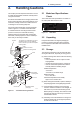
2-1 <2. Handling Cautions> 2. Handling Cautions This chapter provides important information on how to handle the transmitter. Read this carefully before using the transmitter. EJX Series transmitters are thoroughly tested at the factory before shipment. When taking delivery of an instrument, visually check them to make sure that no damage occurred during shipment. Also check that all transmitter mounting hardware shown in figure 2.1 is included.
- NOTE When storing the instrument with a battery pack, it is recommended to put the instrument in Deep Sleep mode to conserve the batteries. For details on how to switch to Deep Sleep mode, refer to subsection 8.3.16 “Switching to Deep Sleep Mode”. 2.4 2-2 <2. Handling Cautions> Selecting the Installation Location The transmitter is designed to withstand severe environmental conditions.
The following precautions must be observed in order to safely operate the transmitter under pressure. (a) Make sure that all the process connector bolts are tightened firmly. (b) Make sure that there are no leaks in the impulse piping. (c) Never apply a pressure higher than the specified maximum working pressure. 2.
NOTE When storing the instrument with a battery pack, it is recommended to put the instrument in Deep Sleep mode to conserve the batteries. For details on how to switch to Deep Sleep mode, refer to subsection 8.3.16 “Switching to Deep Sleep Mode”. 2.
<2. Handling Cautions> [Installation Diagram] Amplifier housing code 7 Hazardous Location Transmitter Battery Pack [Intrinsically Safe] Class I, II, III, Division 1, Groups A,B,C,D,E,F,G Class I, Zone 0 in Hazardous (Classified) Locations AEx ia IIC [Nonincendive] Class I, II, Division 2, Groups A,B,C,D,F,G Class III, Division 1.
2-6 <2. Handling Cautions> Note 2. Installation • Installation should be in accordance with local installation requirements.
2.8.4 IECEx Certification (2) Operation Caution for IECEx Intrinsically safe type. WARNING Take care not to generate mechanical sparking when access to the instrument and peripheral devices in a hazardous location. (3) Maintenance and repair WARNING The instrument modification or parts replacement by other than an authorized Representative of Yokogawa Electric Corporation is prohibited and will void the certification. (4) Name Plate SUPPLY OUTPUT MWP mA DC V DC Note 2.
2-8 <2. Handling Cautions> Note 4. Battery Pack • Use only YOKOGAWA battery pack F9915MA or F9915NS. 2.10 Pressure Equipment Directive (PED) Note 5. Special conditions for Safe Use • In case the enclosure of the Pressure Transmitter is made of aluminum, if it is mounted in an area where the use of apparatus of equipment protection level Ga is required, it must be installed such, that, even in the event of rare incidents, ignition sources due to impact and friction sparks are excluded.
(3) Operation CAUTION • The temperature and pressure of fluid should be maintained at levels that are consistent with normal operating conditions. • The ambient temperature should be maintained at a level that is consistent with normal operating conditions. • Please take care to prevent water hammer and the like from inducing excessive pressures in pipes and valves. If phenomena are likely, install a safety valve or take some other appropriate measure to prevent pressure from exceeding PS.
NOTE This equipment has been tested and found to comply with the limits for a Class A digital device, pursuant to part 15 of the FCC Rules. These limits are designed to provide reasonable protection against harmful interference when the equipment is operated in a commercial environment. This equipment generates, uses, and can radiate radio frequency energy and, if not installed and used in accordance with the instruction manual,may cause harmful interference to radio communications.
3. 3-1 <3.
4. 4.1 <4. Installation> 4-1 Installation Precautions Before installing the transmitter, read the cautionary notes in section 2.4, “Selecting the Installation Location.” For additional information on the ambient conditions allowed at the installation location, refer to subsection 11.1 “Standard Specifications.” 4.2 ■ ■ NOTE To connect this transmitter to the Field Wireless Network, information for connecting to the field wireless devices needs to be set beforehand. Refer to 7.
4-2 <4.
4.3 Changing the Process Connection 4.4 The transmitter is shipped with the process connection specified at the time of ordering. To change the process connection, the drain (vent) plug must be repositioned. To reposition a drain (vent) plug, refer to Figure 4.4 and use a wrench slowly and gently to unscrew it. Then, remove and remount it on the opposite side.
<4. Installation> 4.5 4.4.2 Using the Configuration Tool This method is applicable only to the Model EJX110B. With a configuration tool, you can change which process connection is used as the high-pressure side without mechanically rotating the pressuredetector section 180 as described in subsection 4.4.1.
4-5 <4. Installation> 4.7 Vertical impulse piping type Pressure-detector section Changing the direction of the antenna Adjust the direction of the antenna to be in the upright position. Figure4.8 shows factory setup antenna position. If the transmitter is installed to vertical impulse piping, follow the procedure below and change the antenna position. Rotate 0 to ±180° segments 1) Loosen the two mounting screws at the bottom of the antenna by using a 2.5 mm Allen wrench (see Figure 4.8).
5. 5.1 5-1 <5. Installing Impulse Piping> Installing Impulse Piping Impulse Piping Installation Precautions The impulse piping that connects the process outputs to the transmitter must convey the process pressure accurately. If, for example, gas collects in a liquid-filled impulse line, or the drain for a gas-filled impulse line becomes plugged, it will not convey the pressure accurately.
5-2 <5. Installing Impulse Piping> Pipe-Mounting Type 3-Valve Manifold (Figure 5.2) Direct-Mounting Type 3-Valve Manifold (Figure 5.3) 1) Screw nipples into the connection ports on the transmitter side of the 3-valve manifold, and into the impulse piping connecting ports on the process connectors. (To maintain proper sealing, wind sealing tape around the nipple threads.) 2) Mount the 3-valve manifold on the 50 mm (2inch) pipe by fastening a U-bolt to its mounting bracket.
5.1.2 Routing the Impulse Piping (3) Impulse Piping Slope (1) Process Pressure Tap Angles If condensate, gas, sediment or other extraneous material in the process piping gets into the impulse piping, pressure measurement errors may result. To prevent such problems, the process pressure taps must be angled as shown in figure 5.4 according to the kind of fluid being measured. NOTE • If the process fluid is a gas, the taps must be vertical or within 45° either side of vertical.
Liguid NOTE After completing the connections, close the valves on the process pressure taps (main valves), the valves at the transmitter (stop valves), and the impulse piping drain valves, so that condensate, sediment, dust and other extraneous material cannot enter the impulse piping. 5.2 Impulse Piping Connection Examples Figure 5.5 and 5.6 show examples of typical impulse piping connections.
6. 6.1 <6. Wiring> 6-1 Wiring Mounting Antenna and Wiring For Amplifier housing code 8 and 9, an antenna is not attached to the transmitter. The following provides the instructions for mounting the antenna and installing the remote antenna and wiring using antenna extension cable. IMPORTANT The antenna connector is covered with a cap at the time of delivery. Keep the cap attached until the installation of the antenna or antenna cables to protect the inside connection part.
6-2 <6. Wiring> 6.1.2 Mounting External Antenna and Wiring Antenna Extension Cable 6.1.2.1 Mounting of External Antenna Mount the external antenna at the proper location according to the wireless environment described in 2.4 Selecting the Installation Location. The mounting to the pipe such as 50 mm (2-inch) pipe needs to secure the enough strength to endure a strong wind, vibration and so on. The antenna must be mounted vertically.
6-3 <6. Wiring> Antenna Antenna extension cable 2: 10 m Antenna Protect by self-bonding tape Arrester Grounding cable Antenna extension cable 1: 3 m Protect by self-bonding tape Antenna extension cable 1: 3 m Transmitter body Transmitter body F0604.ai Figure 6.4 Wiring the antenna extension cable CAUTION Use the dedicated antenna extension cable provided by Yokogawa as accessories for the transmitters.
<6. Wiring> 6-4 6.1.2.3 Mounting of Arrester and Wiring 6.2 Mount an arrester between the extension cables and connect the grounding cable to the grounding terminal of the arrester as required. When using the antenna extension cable with an arrestor, Class C grounding with the grounding resistance of 10 Ω is required. Always ground the transmitter case in accordance with national and local electrical codes.
7. Operation 7.1 Preparation for Starting Operation This section describes the operation procedure for the EJX110B as shown in figure 7.1 (vertical impulse piping type, high-pressure connection: right side) when measuring the liquid flow rate, and EJX430B as shown in figure 7.2 when measuring pressure. NOTE It is required to set security and network information to enable the transmitter to be connected to the Field Wireless Network. For more details, refer to section 7.
7-2 <7. Operation> ■ Orifice Tap valve (high pressure) Confirm that transmitter is operating properly by integral indicator. If the transmitter is faulty, an error code is displayed. Tap valve (low pressure) Stop valve (low pressure) 3-valve manifold Self-diagnostic error on integral indicator (Faulity transmitter) Equalizing valve F0703.ai Stop valve (high pressure) Figure 7.3 Drain valve (high pressure) Figure 7.
(1) When you can obtain the Low Range Value from the actual measured value of 0% (0 kPa, atmospheric pressure); ■ Using the transmitter’s zero-adjustment screw Before adjusting zero point, make sure followings. • The External zero trim parameter (External Zero Trim) is “Trim on”. For details, refer to section 8 “Setting Parameters”. • Use a slotted screwdriver to turn the zeroadjustment screw. Turn the screw clockwise to increase the output or counterclockwise to decrease the output.
n thi wi 2) Creating a provisioning information file The following provisioned information is stored in the provisioning information file. cm 30 • • • • • F0705.ai Figure 7.5 ■ 7-4 <7. Operation> Provisioning Example Provisioning work This subsection describes provisioning work using FieldMate as the provisioning device. Provisioning work performs provisioning for each field wireless device using FieldMate and an infrared adapter.
<7. Operation> (a) Deep sleep 7-5 NOTE F0707.ai (b) Ready and pause If the transmitter searches the Field Wireless Network for long time at low ambient temperature condition, sometimes error “AL.70 LOWBAT” is displayed on the Integral Indicator. Even though using new batteries, it can occur. It occurs because of battery characteristics. After joining to the Field Wireless Network, this error will be cleared within one hour if battery has no failure. 7.
7.6 7-6 <7. Operation> Venting or Draining Transmitter Pressuredetector Section Since this transmitter is designed to be selfdraining and self-venting with vertical impulse piping connections, neither draining nor venting will be required if the impulse piping is configured appropriately for self-draining or self-venting operation. If condensate (or gas) collects in the transmitter pressure-detector section, the measured pressure may be in error.
8. Setting Parameters This transmitter can remotely handle range changes, Tag No. setup, monitoring of selfdiagnostic results, and Zero Point Adjustment, etc. according to communication with the field wireless configuration tool or the device configuration tool. 8.1 8-1 <8. Setting Parameters> Environment for parameter setting After installing the battery pack, perform provisioning and have the transmitter join the field wireless network.
Table 8.1 8-2 <8. Setting Parameters> Parameter Usage and Selection Item Tag No Description Output Sets the tag No. as Device Tag (Software Tag). Sixteen characters (alphanumeric characters, including - and •) can be set. The process variable and the diagnostic result can be output.
8-3 <8.
8-4 <8. Setting Parameters> Online Menu (continued) (AI1 DP) • Block Info • Block Mode • Dynamic Variables • Configuration • Calibration • Others (Block Info) • Tag Description (Block Mode ) • Mode.Target • Mode.Actual • Mode.Permitted • Mode.Normal (Dynamic Variables) • Process Value • Simulation (Process Value) • Process Value.Status • Process Value.
8-5 <8. Setting Parameters> Online Menu (continued) (AI2 SP) • Block Info • Block Mode • Dynamic Variables • Configuration • Others (Block Info) • Tag Description (Block Mode ) • Mode.Target • Mode.Actual • Mode.Permitted • Mode.Normal (Dynamic Variables) • Process Value • Simulation (Process Value) • Process Value.Status • Process Value.
8-6 <8. Setting Parameters> Online Menu (continued) (AI3 Temp) (Block Info) • Block Info • Block Mode • Dynamic Variables • Configuration • Others • Tag Description (Block Mode ) • Mode.Target • Mode.Actual • Mode.Permitted • Mode.Normal (Dynamic Variables) • Process Value • Simulation (Process Value) • Process Value.Status • Process Value.
8-7 <8. Setting Parameters> (b) Detachable antenna type (Amplifier housing code: 8 or 9) Online Menu • UAPMO • UDO • CO • TRANSDUCER • AI1 DP • AI2 SP • AI3 Temp (UAPMO) • Configuration • Diagnostics • Alerts • Power Status • Identification (Configuration) • UAP Option • Hardware Write Protect • Static Revision • Reset Energy Left • Radio Silence • Energy Harvest Type (Diagnostics) • Diagnostic Status • Diagnostic Status Detail.1 • Diagnostic Status Detail.
8-8 <8. Setting Parameters> Online Menu (continued) (AI1 DP) • Block Info • Block Mode • Dynamic Variables • Configuration • Calibration • Others (Block Info) • Tag Description (Block Mode ) • Mode.Target • Mode.Actual • Mode.Permitted • Mode.Normal (Dynamic Variables) • Process Value • Simulation (Process Value) • Process Value.Status • Process Value.
8-9 <8. Setting Parameters> Online Menu (continued) (AI2 SP) • Block Info • Block Mode • Dynamic Variables • Configuration • Others (Block Info) • Tag Description (Block Mode ) • Mode.Target • Mode.Actual • Mode.Permitted • Mode.Normal (Dynamic Variables) • Process Value • Simulation (Process Value) • Process Value.Status • Process Value.
<8. Setting Parameters> 8-10 Online Menu (continued) (AI3 Temp) (Block Info) • Block Info • Block Mode • Dynamic Variables • Configuration • Others • Tag Description (Block Mode ) • Mode.Target • Mode.Actual • Mode.Permitted • Mode.Normal (Dynamic Variables) • Process Value • Simulation (Process Value) • Process Value.Status • Process Value.
8-11 <8. Setting Parameters> (2) Menu Tree The menu tree of the device configuration tool of our recommendation is shown below. Refer to Subsection 9.2 “Calibration Instruments Selection” for the device configuration tool of our recommendation.
8-12 <8. Setting Parameters> Online Menu (continued) Device Configuration (continued) (AI2 SP) (Block Info) • Configure/Setup • Tag Description (Block Mode) • Mode.Target • Mode.Actual • Mode.Permitted • Mode.Normal (Configuration) (Block Mode) • Block Mode • Concentrator OID • Scale * • Process Value Filter Time • Mode.Target • Mode.Actual • Mode.Permitted • Mode.Normal (Scale) • Scale.EU at 100% * • Scale.EU at 0% * • Scale.Units Index * • Scale.
<8. Setting Parameters> 8-13 Online Menu (continued) (Diagnostic) (UAPMO) (Diagnostics/Alerts) • UAPMO • Device Diagnostics • Diagnostic Status • Diagnostic Status Detail1, • Diagnostic Status Detail2 • Diagnostic Switch • Diagnostic Configuration (Power Status) • Energy Left • Power Supply Status (Process Variable) • AI1 DP • AI2 SP • AI3 Temp (AI1 DP) • Process Variable (Dynamic Variables) (Process Value) • Process Value • Simulation • Process Value.Status • Process Value.
8-14 <8.
Menu (Online) (continued) 8-15 <8. Setting Parameters> Device Configuration (continued) (AI2 SP) (Block Info) • Configure/Setup • Tag Description (Block Mode) • Mode.Target • Mode.Actual • Mode.Permitted • Mode.Normal (Configuration) (Block Mode) • Block Mode • Concentrator OID • Scale * • Process Value Filter Time • Mode.Target • Mode.Actual • Mode.Permitted • Mode.Normal (Scale) • Scale.EU at 100% * • Scale.EU at 0% * • Scale.Units Index * • Scale.
8-16 <8. Setting Parameters> Menu (Online) (continued) (Diagnostic) (UAPMO) (Diagnostics) • UAPMO • Device Diagnostics • Diagnostic Status • Diagnostic Status Detail.1 • Diagnostic Status Detail.2 • Diagnostic Switch • Diagnostic Configuration (Diagnostic Configuration) (Power Status) • Energy Left • Power Supply Status • Power Supply Voltage (Process Variable) • AI1 DP • AI2 SP • AI3 Temp (AI1 DP) • Process Variable • Diagnostic.Other Faults • Diagnostic.Faults Non-Compliance • Diagnostic.
8.3.3 Parameters for Wireless Communication (1) Network Information Concentrator object block: Configuration Allows confirming the network information. (2) Update Time CO block: Data publication period Sets the update time value to 0.5 to 3,600 seconds. When amplifier housing code 7 is specified, note that more than one second is available. The setting affects the battery life. When update time is set 0 seconds, the transmitter is stopped to update process variables by way of the field wireless network.
NOTE When the device detects AL01 and AL02, the LCD display stays on regardless of the status in LCD mode. See Table 9.3 and 9.4 Error Message Summary for details. 8.3.4 Tag and Device Information If these are specified when ordering, the designated Tag No. and device information are set and shipped. Tag No. and device information can be checked as follows. • Procedure to call up the tag No.
8.3.8 Output Signal Low Cut Mode Setup Low cut mode can be used to stabilize the output signal near the zero point. ( There is 10% of hysteresis at only point of transition from low to high) [Setup Low Cut Value] • Procedure to call up the Lower cutoff* display AI1 block: Lower cutoff* Example: setup LOW_CUT of output to 15% Lower cutoff* = (“Eu at 100%” - “Eu at 0%”) × 0.15 + “Eu at 0%” *: “Low Cutoff” is used instead of “Lower cutoff” for Detachable antenna type (Amplifier housing code: 8 or 9).
8-20 <8. Setting Parameters> 8.3.11 Integral Indicator Scale Setup 8.3.12 Unit for Displayed Temperature The following three displays are available for the integral indictor: differential pressure/pressure, static pressure, and temperature. The following three variables can be displayed on the integral indicator: % of differential pressure range, % of static pressure range, and % of temperature range. When the instrument is shipped, the temperature units are set to C (Centigrade).
8-21 <8. Setting Parameters> 8.3.14 Zero Point Adjustment and Span Adjustment b. Each EJX-B Series Differential Pressure/Pressure Transmitter is characterized by factory. But there are some errors caused by environment and installed posture. Like tank level measurement that is impossible to set actual level to zero, output value is adjustment to actual level by other measurement using glassgage. There are Zero and Span Adjustments to fine-tune those errors.
c. Using External Zero-adjustment Screw External Zero-adjustment parameter (External Zero Trim) can set permission or prohibition to adjustment by External Zero-adjustment Screw. Set “Trim on” to use the External Zero-adjustment Screw. (“Trim on” at shipment) Use a slotted screwdriver to turn the zeroadjustment screw. Equalize the transmitter, then turn the screw clockwise to increase the output or counterclockwise to decrease the output. The zero point adjustment can be made with a resolution of 0.
(4) Reset Adjustment Reset Adjustment clear the amount of adjustment. Reset Ajustment can be performed using CAL_ CLEAR of the differential pressure (AI1 block) Cal Cmd parameter for the input pressure and using CAL_CLEAR of the static pressure (AI2 block) Cal Cmd parameter for the static pressure. After Reset Adjustment, confirm the status by using Cal Status of the cleared block. The amount of adjustment made by the external zero-adjustment screw can be reset to the initial setting as well.
8.4 <8. Setting Parameters> Self-Diagnostics UAPMO block: Diagnostic Status 8.4.1 Identify Problems by Using the Device Configuration Tool First, check Diagnostic Status of the self-diagnostic result. Table 8.
<8. Setting Parameters> 8-25 8.4.2 Alert Report EJX generates alert information related to Diagnostic Status and automatically sends to a field wireless gateway. To use this function, the following alert setting is necessary. When “Out of Service” for Diagnostic Status alert is required, choose “FALSE” for [Out of Service.Alert Disable] in the UAPMO block. Refer to the field wireless gateway User’s Manual for the setting procedure to obtain the alert information from the gateway.
Table 8.5 8-26 <8. Setting Parameters> Diagnostic Results Summary Diagnostic Status Contents Faults in electronics Faults in sensor or actuator element Installation, calibration problem Out of service Outside sensor limits Alert Type 78 77 76 75 74 NAMUR NE107 Category F F C O C Environmental conditions out of device specification. 73 O Power is critical low: maintenance need shortterm.
<8. Setting Parameters> 8-27 8.4.3 Checking with Integral Indicator NOTE If an error is detected by running self-diagnostics, an error number is displayed on the integral indicator. If there is more than one error, the error number changes at three-second intervals. See Table 9.3 regarding the error codes. F0808.ai Figure 8.
9. 9.1 Maintenance Overview WARNING Since the accumulated process fluid may be toxic or otherwise harmful, take appropriate care to avoid contact with the body or inhalation of vapors when draining condensate or venting gas from the transmitter pressure-detector section and even after dismounting the instrument from the process line for maintenance. Maintenance of the transmitter is easy due to its modular construction.
Table 9.1 9-2 <9. Maintenance> Instruments Required for Calibration Name Provisioning device tool Yokogawa-recommended Instrument • FieldMate (R2.02.01 or later) • Provisioning Device Tool • Infrared Adapter certified by Yokogawa Supplier: ACTiSYS Product name: IrDA InfraRed USB Adaptor Product number: IR224UN • Field Wireless Integrated Gateway attached Software Field Wireless Configurator Field Wireless Management Tool • Field Wireless System related Product Plant Resource Manager (PRM) (R3.
9.4 Disassembly and Reassembly CAUTION Precautions for the intrinsic safety explosion prevention type instrument Intrinsic safe type transmitters must be, as a rule, removed to a non-hazardous area for maintenance and be disassembled and reassembled to the original state. Check and confirm the insulation when it is reassembled to the original state. Check and confirm the insulation when it is reassembled to the original state. Refer to section 2.
■ ■ Attaching the Integral Indicator 1) Align both the integral indicator and RF assembly connectors and engage them. 2) Insert and tighten the two mounting screws. 3) Replace the cover. Power cable Press Forward Integral indicator Boss CPU assembly RF assembly Mounting screw Zero adjustment screw Zero-adjustment screw pin Amplifier cover F0902.ai Removing and Attaching Integral indicator, RF assembly and CPU Assembly 9.4.
3) Align and engage the zero-adjustment screw pin with the groove on the bracket on the CPU assembly. Then insert the CPU assembly straight onto the post in the amplifier case. 4) Tighten the two bosses. Mount the RF assembly, and the integral indicator (refer to subsections 9.4.1 and 9.4.2). IMPORTANT Confirm that the zero-adjustment screw pin is placed properly in the groove on the bracket prior to tightening the two bosses. If it is not, the zeroadjustment mechanism will be damaged.
9-6 <9. Maintenance> 3) After the pressure-detector section has been reassembled, a leak test must be performed to verify that there are no pressure leaks. 4) Reattach the transmitter section to the pressure-detector section. 5) Reattach the stopper and stopper bolt. Tighten the five set screws. (Tighten the screws to a torque of 1.5 N·m) 6) Install the CPU assembly according to subsection 9.4.3. 7) After completing reassembly, adjust the zero point and recheck the parameters.
■ <9. Maintenance> 9.4.8 Handling Batteries Remounting 1) Insert the new battery pack lightly. 2) Push the center of the battery pack and insert it securely. 3) Tighten the two battery pack mounting screws to a torque of approximately 0.7 N·m. 4) Replace the terminal box cover. 9.4.7 Replacing the Batteries The batteries in the battery pack can be replaced. Batteries are not installed when shipped from the factory. Assemble the battery pack as follows.
■ Transportation of products containing lithium batteries: Batteries used for this transmitter contain lithium. Primary lithium batteries are regulated in transportation by the U.S. Department of Transportation, and are also covered by the International Air Transport Association (IATA), the International Civil Aviation Organization (ICAO), and the European Ground Transportation of Dangerous Goods (ARD).
9-9 <9. Maintenance> 9.5.2 Troubleshooting Flowcharts : Areas where self-diagnostic offers support Abnormalities appear in measurement. YES The following sorts of symptoms indicate that transmitter may not be operating properly. Example : • There is no output signal. • Output signal does not change even though process variable is known to be varying. • Output value is inconsistent with value inferred for process variable. Is process variable itself abnormal? NO Inspect the process system.
9-10 <9. Maintenance> Large output error. Output travels beyond 0% or 100%. Connect the device configuration tool and check self-diagnostics. Does the selfdiagnostic indicate problem location? NO YES YES YES NO Fully close equalizing valve, and fully open high pressure and low pressure valves. NO YES Refer to individual model user manuals and connect piping as appropriate for the measurement purpose.
<9. Maintenance> 9-11 9.5.3 Errors and Countermeasures Table 9.3 Integral indicator Error Message Summary (Causes and Actions) Factory NAMUR category Bit Diagnostic Status Diagnostic Status Detail Cause FC_SENSOR_FAIL FR_SENSOR_FAIL AL. 01 CAP.
Integral indicator <9.
Integral indicator <9. Maintenance> Factory NAMUR category Bit Diagnostic Status AL. 63 AI SIM C Bit 17 Simulation is active AL. 64 AI SIM AL. 65 AI SIM *1: *2: *3: *4: C Bit 17 Simulation is active Diagnostic Status Detail Cause SimulationActive (AI1) AI1 block is simulate mode. SimulationActive (AI2) AI2 block is simulate mode. SimulationActive (AI3) AI3 block is simulate mode.
Table 9.4 Error Message Summary (Output Actions) Factory Integral NAMUR Indicator category Bit Diagnostic Status Output actions Diagnostic Status Detail FC_SENSOR_FAIL FR_SENSOR_FAIL FC_UNOSC_FAIL FR_UNOSC_FAIL CAP_T_SENSOR_FAIL AL. 01 CAP. ERR F *2 Faults in sensor or Bit 26 actuator element CAP_EEPROM_FAIL CAP_EEP_IRREGULAR AMP_T_SENSOR_FAIL*3 AMP_EEPROM_FAIL AMP_EEP_IRREGULAR AL. 02 AMP.ERR F *2 9-14 <9.
<9. Maintenance> Factory Integral NAMUR Indicator category Bit Diagnostic Status Output actions Diagnostic Status Detail DP_OUTSIDE_LIMIT AL. 10 PRESS SP_OUTSIDE_LIMIT AL. 11 ST. PRSS O Bit 23 Outside sensor limits CAPT_OUTSIDE_LIMIT AL. 12 CAP. TMP AMPT_OUTSIDE_LIMIT AL. 13 AMP. TMP DP_TRIM_SPAN_ OUTSIDE AL. 53 P. ADJ DP_TRIM_ZERO_ OUTSIDE AL. 53 P. ADJ C AL. 55 SP. ADJ Installation, Bit 25 calibration problem SP_TRIM_SPAN_ OUTSIDE SP_TRIM_ZERO_ OUTSIDE AL. 55 SP.ADJ AL. 79 OV.
<9. Maintenance> Factory Integral NAMUR Indicator category AL. 30 RANGE AL. 31 SP. RNG O AL. 70*6 LOWBAT M AL. 70*6 LOWBAT Bit Diagnostic Status Output actions Diagnostic Status Detail Environmental DP_OUTSIDE_RANGE conditions out Bit 22 of device SP_OUTSIDE_RANGE specification Power is critical low: Bit 20 maintenance need short - term Power is low: Bit 19 maintenance need mid - term CRITICAL_LOWBAT*4 Bit 24 O/S AI3_OUT_OF_SERVICE AL.
10-1 <10. Parameter Summary> 10. Parameter Summary Table 10.1 Object ID 1. UAPMO block Parameter Attribute Label ID 1 Version Revision 10 Static Revision 64 65 Identification Number CTS Version 66 ITS Version 67 Diagnostic Status 68 UAP Option Default value Description Indicates the application revision of EJX This revision when the application software is downloaded.
Object ID 1. UAPMO block (continued) 10-2 <10. Parameter Summary> Attribute ID Label Default value Description Handling 105 Power Supply Status Indicates the predicted battery level and the power supply method. 0 = external power supply 1 = battery level 75% or more 2 = battery level 25% ~ 75% 3 = battery level 25% or less R 106 EHType*2 Available to write note into this parameter. --- W 107 Power Supply Voltage*2 Indicates the measured power supply voltage (V).
Object ID 1. UAPMO block (continued) 2. UDO block 3. CO block 10-3 <10. Parameter Summary> Attribute ID Label Default value Description Handling 121 Faults Sensor or actuator Alert*2 The On/Off or priority for Faults Sensor or actuator Alert can be set. 1. On/Off setting 0 = FALSE, 255 =TRUE 2. Alert report priority: 0 to 15 1. TRUE 2. 15 W 122 Faults Electronics Alert*2 The On/Off or priority for Faults Electronics Alert can be set. 1. On/Off setting 0 = FALSE, 255 =TRUE 2.
Object ID 10-4 <10. Parameter Summary> Attribute ID Label Default value Description Handling 3. CO block (continued) 4 PUB_ITEM_MAX Maximum PUB_ITEM value --- R 5 PUB_ITEM_NUM PUB_ITEM number --- R 6 PUB_ITEM Indicates the PUB_ITEM information. The following shows the components 1. ObjectID 2. AttributeID 3. AttributeIndex 4. Size --- W 4. TRANSDUCER block 1 Tag Description Memo field available to write anything.
Object ID 4. TRANSDUCER block (continued) 5. AI1 block 10-5 <10. Parameter Summary> Attribute ID Label Default value Description Handling 11 Special Order ID Displays the special order number, if applicable. --- R 12 Unit Sel1 Selects whether to automatically apply the unit to the word for the parameter for which the unit display is selected, or apply the characters that are written to Display Unit1.
Object ID 5. AI1 block (continued) 10-6 <10. Parameter Summary> Attribute ID Label Default value Description Handling 52 Lower Limit Indicates the lower limit (LRL) for the pressure. --- R 53 PV Range Sets the measurement range. 1. EU at 100% : Indicates input value of the upper limit. 2. EU at 0% : Indicates input value of the lower limit. 3. Units Index : Indicates the units of the measurement range. 4. Decimal : Indicates the digit number below the decimal point.
Object ID 5. AI1 block (continued) 6. AI2 block 10-7 <10. Parameter Summary> Attribute ID Label Default value Description Handling 107 T Zero Cmp Parameter to select the temperature zero shift compensation mode 0 = OFF : Does not perform temperature zero shift compensation. 1 = ON : Performs temperature zero shift compensation.
Object ID 6. AI2 block (continued) 7. AI3 block 10-8 <10. Parameter Summary> Attribute ID Label Default value Description Handling 53 PV Range Sets the measurement range. 1. EU at 100% : Indicates input value of the upper limit. 2. EU at 0% : Indicates input value of the lower limit. 3. Units Index : Indicates the units of the measurement range. 4. Decimal : Indicates the digit number below the decimal point. 1. EU at 100% = 25000.
Object ID 7. AI3 block (continued) 10-9 <10. Parameter Summary> Attribute ID Label Default value Description Handling 2 Block Mode A universal parameter to indicate the block’s operation status. O/S, Auto, and Man can be selected. 1. Target : Specify Al object mode. 2. Actual : Indicates current mode of Al object. 3. Permitted : Indicates the mode selected by Target of Al object. 4. Normal : Indicate normal status mode of Al object. 1. Target = Auto 2. Actual = Auto 3.
Table 10.
11. General Specifications 11.1 Standard Specifications Communication protocol: ISA100.11a protocol EJX430B Measurement Span/Range 250 kbps A Frequency: 2400 - 2483.5 MHz license free ISM band Radio security: Antenna: Span and range limits: EJX110B M mbar(/D3) mmH2O(/D4) Span 0.1 to 5 0.4 to 20 1 to 50 10 to 500 Range -5 to 5 -20 to 20 -50 to 50 -500 to 500 Span 0.1 to 10 0.4 to 40 1 to 100 10 to 1000 Range -10 to 10 -40 to 40 -100 to 100 -1000 to 1000 Span 0.
Working Pressure Limits (Silicone oil) Maximum Pressure Limits: EJX110B Capsule F, L M, H, V Pressure 16 MPa (2300 psi) 25 MPa (3600 psi)* * 16 MPa for wetted parts material code H, M, T, A, D, and B. EJX310B Capsule L M A B Pressure 10 kPa abs (2.95 inHg abs) 130 kPa abs (38 inHg abs) 3.5 MPa abs (500 psia) 16 MPa abs (2300 psia) EJX430B Capsule H A B 11-2 <11. General Specifications> Pressure 500 kPa (2000 inH2O) 3.
<11. General Specifications> 11-3 Minimum Pressure Limit: See graph below EJX110B and EJX430B Atmospheric pressure 100(14.5) Working pressure kPa abs (psi abs) 10(1.4) Applicable range 2.7(0.38) 1(0.14) -40 (-40) 0 (32) 40 (104) 80 (176) Process temperature °C (°F) 120 (248) F01.ai EJX310B 100(750) M,A and B capsule L capsule 10(75) 2.7(20) Working pressure 1(7.5) kPa abs (mmHg abs) Applicable range 0.46 (3.45) 0.13(1) 0.1(0.75) 0.013(0.1) 0.01(0.
<11. General Specifications> 11-4 11.2 Model and Suffix Codes Model EJX110B Model Suffix Codes EJX110B ...................... Output signal -L . . . . . . . . . . . . . . . . . . . . . Measurement F . . . . . . . . . . . . . . . . . . . span (capsule) L . . . . . . . . . . . . . . . . . . . M . . . . . . . . . . . . . . . . . . . H . . . . . . . . . . . . . . . . . . . V . . . . . . . . . . . . . . . . . . . . . . . . . . . . . . . . . . . . Wetted parts material *1 Process connections 0 . . .
Table 1. Wetted Parts Materials Wetted parts material code Cover flange and process connector S# ASTM CF-8M *1 H ASTM CF-8M *1 M T ASTM CF-8M *1 A D B 11-5 <11.
<11. General Specifications> 11-6 Model EJX310B Model Suffix Codes EJX310B ...................... Output -L . . . . . . . . . . . . . . . . . . . . . signal Measurement L . . . . . . . . . . . . . . . . . . . span (capsule) M . . . . . . . . . . . . . . . . . . . A . . . . . . . . . . . . . . . . . . . B . . . . . . . . . . . . . . . . . . . Wetted parts S . . . . . . . . . . . . . . . . . material *1 0 . . . . . . . . . . . . . . . Process 1 . . . . . . . . . . . . . . . connections 2 . . . .
11-7 <11. General Specifications> Model EJX430B Model Suffix Codes EJX430B ...................... Output -L . . . . . . . . . . . . . . . . . . . . . signal Measurement H . . . . . . . . . . . . . . . . . . . span (capsule) A . . . . . . . . . . . . . . . . . . . B . . . . . . . . . . . . . . . . . . . Wetted parts . . . . . . . . . . . . . . . . . material *1 0 . . . . . . . . . . . . . . . Process 1 . . . . . . . . . . . . . . . connections 2 . . . . . . . . . . . . . . . 3 . . . . . . . .
<11. General Specifications> 11-8 11.
11-9 <11.
11-10 <11.
11-11 <11. General Specifications> 11.4 Dimensions [EJX110B] Vertical impulse piping type (Installation code 7 and Amplifier housing code 7) Unit: mm (approx. inch) Wetted parts material code: S (except for Measurement span code F) 6 (0.24) For electrical connection code 5, 9, A, and D 76 (2.99) 97 (3.82) 305*6 (12.00) 238*6 (9.37) 91 (3.58) 191 (7.52) 39 Mounting bracket (L-type, optional) Zero adjustment Ground terminal 211 (8.31) 64 (2.52) 2-inch pipe (O. D.
11-12 <11. General Specifications> Unit: mm (approx. inch) Vertical impulse piping type (Installation code 7 and Amplifier housing code 7) 319*8 (12.56) 257*8 (10.12) 105 (4.13) 97 (3.82) 191 (7.52) 36*4 27*5 (1.06) (1.42) 64 (2.52) 2-inch pipe (O. D. 60 mm) Vent/Drain plugs Integral indicator Ø110 (4.33) 176*6 (6.93) 102 (4.02) 46 (1.81) 72 (2.83) 234 (9.21) 52 (2.05) 140 (5.51) Mounting bracket (L-type, optional) 148 (5.83)*2 For electrical connection code 5, 9, A, and D 76 (2.
11-13 <11. General Specifications> Unit: mm (approx. inch) Universal flange type (Installation code U and Amplifier housing code 7) (except for Measurement span code F) 191 (7.52) 82*4 (3.23) 24 (0.94) 140 (5.51) Drain plug 39 Zero adjustment 331*2 (13.03) 211 (8.31) 76 (2.99) 181 (7.13) 6 (0.24) Integral indicator Vent plug Drain plug 41 (1.61) 67 58 (2.28) (2.64) 115 (4.53) (1.54) 64 (2.52) Ø110 (4.
11-14 <11. General Specifications> Unit: mm (approx. inch) Bottom process connection type (Installation code B and Amplifier housing code 7) 191 (7.52) 82*2 (3.23) 24 (0.94) 39 64 (2.52) (1.54) 129 (5.08) Integral indicator Process connector (Optional) For electrical connection code 5, 9, A, and D 6 (0.24) 375*1 (14.76) B Mounting bracket (Optional) 140 (5.51) Vent plug 79 (3.11) 76 (2.99) Process connection High Pressure Side 93 (3.66) A Ground terminal 255 (10.04) Ø110 (4.
11-15 <11. General Specifications> Unit: mm (approx. inch) [EJX310B and EJX430B] Vertical impulse piping type (Installation code 7 and Amplifier housing code 7) *1 6 (0.24) Wetted parts material code: S For electrical connection code 5, 9, A, and D 97 (3.82) 305*6 (12.00) 238*6 (9.37) 91 (3.58) 191 (7.52) 39 (1.54) 24 (0.94) 2-inch pipe Vent/Drain plugs Zero adjustment 138 (5.43)*2 Ø110 (4.33) Open to atmosphere Ø10 (0.
11-16 <11. General Specifications> Unit: mm (approx. inch) Vertical impulse piping type (Installation code 7 and Amplifier housing code 7) *1 319*6 (12.56) 257*6 (10.12) For electrical connection code 5, 9, A, and D 97 (3.82) 2-inch pipe Vent/Drain plugs 148 (5.83)*3 Ø110 (4.33) Open to atmosphere Ø10 (0.39) Integral indicator Zero adjustment 27 (1.06) High pressure side Ground terminal Process connector (Optional) Process Connection 64 (2.52) (O. D. 60 mm) 176*4 (6.93) 140 (5.
11-17 <11. General Specifications> Unit: mm (approx. inch) Universal flange type (Installation code U and Amplifier housing code 7) 191 (7.52) 82 (3.23) 24 (0.94) For electrical connection code 5, 9, A, and D 140 (5.51) Drain plug (1.54) Open to atmosphere Ø5 (0.20)*1 Vent plug Drain plug 41 (1.61) Process connection 58 67 (2.28) (2.64) High pressure side 59*1 (2.32) Process connector (Optional) 115 (4.53) 64 (2.52) Ø110 (4.33) 331*3 (13.03) 211 (8.31) 76 (2.99) 181 (7.
<11. General Specifications> 11-18 Infrared Configuration Infrared port F09.ai .
i Revision Information Title : EJX110B, EJX310B and EJX430B Differential Pressure and Pressure Transmitters Manual No. : IM 01C27B01-01EN Edition 1st 2nd 3rd Date May 2009 Aug. 2010 Oct. 2010 4th Apr. 2011 5th 6th 7th Dec. 2011 Aug. 2012 Oct. 2012 8th 9th June 2013 Jan. 2014 Page — — 2-5 2-6 11-6 — 9-7 — — 2-5, 2-6 11-2 — — Revised Item New publication Release of ISA100.11a protocol 2.8.3 Add description of CENELEC ATEX (KEMA) Certification) 2.8.4 Add description of IECEx Certification 11.