User’s Manual EJX118B and EJX438B Diaphragm Sealed Differential Pressure and Pressure Transmitters IM 01C27H01-01EN IM 01C27H01-01EN Yokogawa Electric Corporation 8th Edition
i EJX118B and EJX438B Diaphragm Sealed Differential Pressure and Pressure Transmitters IM 01C27H01-01EN 8th Edition Contents 1. 2. 3. Introduction................................................................................................ 1-1 1.1 Safe Use of This Product ................................................................................. 1-2 1.2 Radio Wave......................................................................................................... 1-3 1.3 Warranty....
ii 4. 5. Installation.................................................................................................. 4-1 4.1 Precautions ....................................................................................................... 4-1 4.2 Mounting the Diaphragm Seals........................................................................ 4-1 4.3 Transmitter Mounting........................................................................................ 4-2 4.
iii 7.4 8. 7.3.8 Output Signal Low Cut Mode Setup................................................. 7-19 7.3.9 Impulse Line Connection Orientation Setup..................................... 7-19 7.3.10 Integral Indicator Display Mode........................................................ 7-19 7.3.11 Integral Indicator Scale Setup........................................................... 7-20 7.3.12 Unit for Displayed Temperature........................................................ 7-20 7.3.
1. Introduction Thank you for purchasing the DPharp EJX Differential Pressure and pressure transmitter. Your EJX Pressure Transmitter was precisely calibrated at the factory before shipment. To ensure both safety and efficiency, please read this manual carefully before you operate the instrument.
Functional grounding terminal Caution This symbol indicates that the operator must refer to an explanation in the user’s manual in order to avoid the risk of injury or death of personnel or damage to the instrument. 1.1 1-2 <1. Introduction> Safe Use of This Product For the safety of the operator and to protect the instrument and the system, please be sure to follow this manual’s safety instructions when handling this instrument.
1.2 Radio Wave IMPORTANT - - - 1.3 This instrument is equipped with a wireless module which is designated as a certification of construction type as a wireless facility for 2.4 GHz band low-power data communication system of the Radio Act. Refer to 2.12 “Regulatory Compliance for Radio and Telecommunication” for detail.
1.5 <1. Introduction> 1-4 ATEX Documentation This is only applicable to the countries in European Union.
2. 2-1 <2. Handling Cautions> Handling Cautions This chapter provides important information on how to handle the transmitter. Read this carefully before using the transmitter. EJX Series transmitters are thoroughly tested at the factory before shipment. When taking delivery of an instrument, visually check them to make sure that no damage occurred during shipment. Also check that all transmitter mounting hardware shown in figure 2.1 is included.
2.4 2-2 <2. Handling Cautions> Selecting the Installation Location The transmitter is designed to withstand severe environmental conditions. However, to ensure that it will provide years of stable and accurate performance, take the following precautions when selecting the installation location.
2.6 Restrictions on Use of Radio Transceivers IMPORTANT Although the transmitter has been designed to resist high frequency electrical noise, if a radio transceiver is used near the transmitter or its external wiring, the transmitter may be affected by high frequency noise pickup. To test this, start out from a distance of several meters and slowly approach the transmitter with the transceiver while observing the measurement loop for noise effects.
2.8 Installation of an ExplosionProtected Instrument If a customer makes a repair or modification to an intrinsically safe instrument and the instrument is not restored to its original condition, its intrinsically safe construction may be compromised and the instrument may be hazardous to operate. Please contact Yokogawa before making any repair or modification to an instrument. CAUTION This instrument has been tested and certified as being intrinsically safe.
Note 5. Special Conditions for safe use POTENTIAL ELECTROSTATIC CHARGING HAZARD-SECURE DISTANCE OF 100MM FROM ANTENNA. DO NOT OPEN WHEN CL II, III, DIV 1,2 ATMOSPHERE IS PRESENT. 2.8.2 CSA Certification Caution for CSA Intrinsically safe type. (Following contents refer to “DOC No. ICS030”) Note 1. Model EJX Series differential, gauge, and absolute pressure transmitters with optional code /CS17 are applicable for use in hazardous locations Certificate: 2325443 • Applicable standard: CAN/CSA-C22.2 No.
2-6 <2. Handling Cautions> Note 2. Installation • Installation should be in accordance with local installation requirements. (Refer to the Control Drawing) (2) Operation WARNING Take care not to generate mechanical sparking when access to the instrument and peripheral devices in a hazardous location.
2-7 <2. Handling Cautions> 2.8.4 IECEx Certification Caution for IECEx Intrinsically safe type. Note 1. Model EJX Series pressure transmitters with optional code /SS27 for potentially explosive atmospheres: • No. IECEx KEM 10.0074X • Applicable Standard: IEC 60079-0: 2011, IEC 60079-11:2011, IEC 60079-26: 2006 • Type of Protection and Marking code: Ex ia IIC T4 Ga • Ambient Temperature: –50°C to 70°C • Process Temperature (Tp.): 120°C max. • Enclosure: IP66/IP67 Note 2.
(2) Technical Data Article 3, Paragraph 3 of PED, denoted as Sound Engineering Practice (SEP). (3) Operation CAUTION • The temperature and pressure of fluid should be maintained at levels that are consistent with normal operating conditions. • The ambient temperature should be maintained at a level that is consistent with normal operating conditions. • Please take care to prevent water hammer and the like from inducing excessive pressures in pipes and valves.
NOTE This equipment has been tested and found to comply with the limits for a Class A digital device, pursuant to part 15 of the FCC Rules. These limits are designed to provide reasonable protection against harmful interference when the equipment is operated in a commercial environment. This equipment generates, uses, and can radiate radio frequency energy and, if not installed and used in accordance with the instruction manual,may cause harmful interference to radio communications.
3. 3-1 <3. Component Names> Component Names EJX118B EJX438B Transmitter section * Flushing connection ring * See below for details Transmitter section * Drain/vent plug * See below for details Capillary tube Diaphragm seal with flushing connection ring Cover flange Diaphragm seal (high pressure side) Cover flange Diaphragm seal (low pressure side) Diaphragm seal Pressuredetector section Pressuredetector section Figure 3.1 F0301.
4. 4.1 4-1 <4. Installation> Installation Precautions Before installing the transmitter, read the cautionary notes in section 2.4, “Selecting the Installation Location.” For additional information on the ambient conditions allowed at the installation location, refer to subsection 10.1 “Standard Specifications.” NOTE To connect this transmitter to the field wireless network, information on connecting to field wireless devices needs to be set beforehand. Refer to 6.
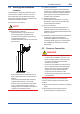
IMPORTANT • When measuring the liquid level of the tank, the minimum liquid level (zero point) must be set to a level at least 50 mm above the center of the high pressure side diaphragm seal (see Figure 4.2). • Correctly install the diaphragm seals on the high and low pressure sides of the process, checking the label on each seal. • To avoid measuring error duets temperature difference between the two diaphragm seals, capillary tube must be bound together.
■ When mounting the bracket on the transmitter, tighten the (four) bolts that hold the transmitter to a torque of approximately 39 N·m {4 kgf·m}. IMPORTANT • • 4-3 <4. Installation> The transmitter should be installed at least 600 mm below the high pressure (HP) process connection to ensure a positive head pressure of fill fluid. Pay special attention to vacuum applications.
4-4 <4. Installation> 4.4 Low pressure side h High pressure (+) side Mounting the Flushing Connection Ring 4.4.1 Mounting to Pressure Detector Section P The flushing connection ring is mounted to the pressure detector section as shown in Figure 4.7. At the factory shipment, the flushing connection ring is already assembled and attached to process detector section. 0 (–) Pressure-detector section F0405.ai Figure 4.
4-5 <4. Installation> IMPORTANT Mating flange Spiral gasket Ring Diaphragm Gasket Pressure-detector section F0408.ai Figure 4.8 Mounting to Process Flange IMPORTANT 1) Position the diaphragm seal so that the diaphragm is in a upward position. 2) Pour the fluorinated oil on the diaphragm and gasket area covering it completely and evenly. Be careful not to scratch the diaphragm or change the its shape. 3) Affix the teflon film over the diaphragm and gasket area.
4-6 <4. Installation> The transmitter section can be rotated approximately 360° (180° to either direction or 360° to one direction from the original position at shipment, depending on the configuration of the instrument.) It can be fixed at any angle within above range. 1) Remove the five setscrews that fasten the transmitter section and capsule assembly, using the Allen wrench. 2) Rotate the transmitter section slowly and stop it at designated position. 3) Tighten the five setscrews to a torque of 1.
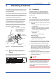
5. 5.1 <5. Wiring> 5-1 Wiring Mounting Antenna and Wiring For Amplifier housing code 8 and 9, an antenna is not attached to the transmitter. The following provides the instructions for mounting the antenna and installing the remote antenna and wiring using antenna extension cable. IMPORTANT The antenna connector is covered with a cap at the time of delivery. Keep the cap attached until the installation of the antenna or antenna cables to protect the inside connection part.
5-2 <5. Wiring> 5.1.2 Mounting External Antenna and Wiring Antenna Extension Cable 5.1.2.1 Mounting of External Antenna Mount the external antenna at the proper location according to the wireless environment described in 2.4 Selecting the Installation Location. The mounting to the pipe such as 50 mm (2-inch) pipe needs to secure the enough strength to endure a strong wind, vibration and so on. The antenna must be mounted vertically.
5-3 <5. Wiring> Antenna Antenna extension cable 2: 10 m Antenna Protect by self-bonding tape Arrester Grounding cable Antenna extension cable 1: 3 m Protect by self-bonding tape Antenna extension cable 1: 3 m Transmitter body Transmitter body F0504.ai Figure 5.4 Wiring the antenna extension cable CAUTION Use the dedicated antenna extension cable provided by Yokogawa as accessories for the transmitters.
<5. Wiring> 5-4 5.1.2.3 Mounting of Arrester and Wiring 5.2 Mount an arrester between the extension cables and connect the grounding cable to the grounding terminal of the arrester as required. When using the antenna extension cable with an arrestor, Class C grounding with the grounding resistance of 10 Ω is required. Always ground the transmitter case in accordance with national and local electrical codes.
6-1 <6. Operation> 6. Operation 6.1 Preparation for Starting Operation This section describes the operation procedure for the EJX118B as shown in Figure 6.1 when measuring liquid level in a closed tank, and EJX438B as shown in Figure 6.2 when measuring pressure in a tank. Diaphragm seal Capillary tube NOTE It is required to set security and network information to enable the transmitter to be connected to the Field Wireless Network. For more details, refer to section 6.
■ Confirm that transmitter is operating properly by integral indicator. • If the transmitter is faulty, an error code is displayed. Self-diagnostic error on integral indicator (Faulity transmitter) F0603.ai Figure 6.3 6-2 <6. Operation> Integral Indicator with Error Code NOTE (1) When you can obtain the Low Range Value from the actual measured value of 0% (0 kPa, atmospheric pressure); ■ Using the transmitter’s zero-adjustment screw Before adjusting zero point, make sure followings.
■ Using the Device Configuration Tool 6.4 Refer to subsection 7.3.14 “Zero-point Adjustment and Span Adjustment”. (2) When you cannot obtain the Low Range Value from the actual measured value of 0%; Adjust the transmitter output to the actual measured value obtained by a glass gauge, etc. [Example] The measuring range of 0 to 2m; the actual measured value of 0.8m Actual measured value= 0.8 x100=40.
■ Provisioning work This subsection describes provisioning work using FieldMate as the provisioning device. Provisioning work performs provisioning for each field wireless device using FieldMate and an infrared adapter. If Yokogawa-recommended infrared device is used for provisioning, distance between the transmitter glass window and the infrared device should be within 30cm. For details of Yokogawarecommended infrared device, refer to subsection 8.2 “Calibration Instruments Selection”.
6-5 <6. Operation> (a) Deep sleep NOTE F0607.ai If the transmitter searches the Field Wireless Network for long time at low ambient temperature condition, sometimes error “AL.70 LOWBAT” is displayed on the Integral Indicator. Even though using new batteries, it can occur. It occurs because of battery characteristics. After joining to the Field Wireless Network, this error will be cleared within one hour if battery has no failure. (b) Ready and pause 6.
<6. Operation> 6-6 WARNING Since the accumulated liquid (or gas) may be toxic or otherwise harmful, take appropriate care to avoid contact with the body, or inhalation of vapors. 6.6.1 Draining Condensate for Flushing Connection Ring 1) Gradually open the drain screw to drain from the flushing connection ring.(See figure 6.7.) 2) When the flushing connection ring is completely drained, close the drain screw. 3) Tighten the drain screw to a torque of 10 N·m {1 kgf·m}.
7. Setting Parameters This transmitter can remotely handle range changes, Tag No. setup, monitoring of selfdiagnostic results, and zero point adjustment, etc. according to communication with the field wireless configuration tool or the device configuration tool. 7.1 7-1 <7. Setting Parameters> Environment for parameter setting After installing the battery pack, perform provisioning and have the instrument join the field wireless network.
Table 7.1 7-2 <7. Setting Parameters> Parameter Usage and Selection Item Tag No. Description Output Sets the tag No. as Device Tag (Software Tag). Sixteen characters (alphanumeric characters, including - and •) can be set. The process variable and the diagnostic result can be output.
<7. Setting Parameters> 7-3 7.3.2 Function Block and Menu Tree (1) Function Block The function of this transmitter is shown below. A specific function might not be able to be used according to the field wireless configuration tool used. When the field wireless configuration tool of our recommendation is used, the software attached to the Field Wireless Integrated Gateway is necessary for setting the dotted line part. Refer to Subsection 8.
7-4 <7. Setting Parameters> Online Menu (continued) (AI1 DP) • Block Info • Block Mode • Dynamic Variables • Configuration • Calibration • Others (Block Info) • Tag Description (Block Mode ) • Mode.Target • Mode.Actual • Mode.Permitted • Mode.Normal (Dynamic Variables) • Process Value • Simulation (Process Value) • Process Value.Status • Process Value.
7-5 <7. Setting Parameters> Online Menu (continued) (AI2 SP) • Block Info • Block Mode • Dynamic Variables • Configuration • Others (Block Info) • Tag Description (Block Mode ) • Mode.Target • Mode.Actual • Mode.Permitted • Mode.Normal (Dynamic Variables) • Process Value • Simulation (Process Value) • Process Value.Status • Process Value.
7-6 <7. Setting Parameters> Online Menu (continued) (AI3 Temp) (Block Info) • Block Info • Block Mode • Dynamic Variables • Configuration • Others • Tag Description (Block Mode ) • Mode.Target • Mode.Actual • Mode.Permitted • Mode.Normal (Dynamic Variables) • Process Value • Simulation (Process Value) • Process Value.Status • Process Value.
7-7 <7. Setting Parameters> (b) Detachable antenna type (Amplifier housing code: 8 or 9) Online Menu • UAPMO • UDO • CO • TRANSDUCER • AI1 DP • AI2 SP • AI3 Temp (UAPMO) • Configuration • Diagnostics • Alerts • Power Status • Identification (Configuration) • UAP Option • Hardware Write Protect • Static Revision • Reset Energy Left • Radio Silence • Energy Harvest Type (Diagnostics) • Diagnostic Status • Diagnostic Status Detail.1 • Diagnostic Status Detail.
7-8 <7. Setting Parameters> Online Menu (continued) (AI1 DP) • Block Info • Block Mode • Dynamic Variables • Configuration • Calibration • Others (Block Info) • Tag Description (Block Mode ) • Mode.Target • Mode.Actual • Mode.Permitted • Mode.Normal (Dynamic Variables) • Process Value • Simulation (Process Value) • Process Value.Status • Process Value.
7-9 <7. Setting Parameters> Online Menu (continued) (AI2 SP) • Block Info • Block Mode • Dynamic Variables • Configuration • Others (Block Info) • Tag Description (Block Mode ) • Mode.Target • Mode.Actual • Mode.Permitted • Mode.Normal (Dynamic Variables) • Process Value • Simulation (Process Value) • Process Value.Status • Process Value.
<7. Setting Parameters> 7-10 Online Menu (continued) (AI3 Temp) (Block Info) • Block Info • Block Mode • Dynamic Variables • Configuration • Others • Tag Description (Block Mode ) • Mode.Target • Mode.Actual • Mode.Permitted • Mode.Normal (Dynamic Variables) • Process Value • Simulation (Process Value) • Process Value.Status • Process Value.
7-11 <7. Setting Parameters> (2) Menu Tree The menu tree of the device configuration tool of our recommendation is shown below. Refer to Subsection 8.2 “Calibration Instruments Selection” for the device configuration tool of our recommendation.
7-12 <7. Setting Parameters> Online Menu (continued) Device Configuration (continued) (AI2 SP) (Block Info) • Configure/Setup • Tag Description (Block Mode) • Mode.Target • Mode.Actual • Mode.Permitted • Mode.Normal (Configuration) (Block Mode) • Block Mode • Concentrator OID • Scale * • Process Value Filter Time • Mode.Target • Mode.Actual • Mode.Permitted • Mode.Normal (Scale) • Scale.EU at 100% * • Scale.EU at 0% * • Scale.Units Index * • Scale.
<7. Setting Parameters> 7-13 Online Menu (continued) (Diagnostic) (UAPMO) (Diagnostics/Alerts) • UAPMO • Device Diagnostics • Diagnostic Status • Diagnostic Status Detail1, • Diagnostic Status Detail2 • Diagnostic Switch • Diagnostic Configuration (Power Status) • Energy Left • Power Supply Status (Process Variable) • AI1 DP • AI2 SP • AI3 Temp (AI1 DP) • Process Variable (Dynamic Variables) (Process Value) • Process Value • Simulation • Process Value.Status • Process Value.
7-14 <7.
Menu (Online) (continued) 7-15 <7. Setting Parameters> Device Configuration (continued) (AI2 SP) (Block Info) • Configure/Setup • Tag Description (Block Mode) • Mode.Target • Mode.Actual • Mode.Permitted • Mode.Normal (Configuration) (Block Mode) • Block Mode • Concentrator OID • Scale * • Process Value Filter Time • Mode.Target • Mode.Actual • Mode.Permitted • Mode.Normal (Scale) • Scale.EU at 100% * • Scale.EU at 0% * • Scale.Units Index * • Scale.
7-16 <7. Setting Parameters> Menu (Online) (continued) (Diagnostic) (UAPMO) (Diagnostics) • UAPMO • Device Diagnostics • Diagnostic Status • Diagnostic Status Detail.1 • Diagnostic Status Detail.2 • Diagnostic Switch • Diagnostic Configuration (Diagnostic Configuration) (Power Status) • Energy Left • Power Supply Status • Power Supply Voltage (Process Variable) • AI1 DP • AI2 SP • AI3 Temp (AI1 DP) • Process Variable • Diagnostic.Other Faults • Diagnostic.Faults Non-Compliance • Diagnostic.
7.3.3 Parameters for Wireless Communication (1) Network Information Concentrator object block : Configuration Allows confirming the network information. (2) Update Time CO block : Data publication period Sets the update time value to 0.5 to 3,600 seconds. When amplifier housing code 7 is specified, note that more than one second is available. When update time is set 0 seconds, the transmitter is stopped to update process variables by way of the field wireless network.
NOTE When the device detects AL01 and AL02, the LCD display stays on regardless of the status in LCD mode. See Table 8.3 and 8.4 Error Message Summary for details. 7.3.4 Tag and Device Information If these are specified when ordering, the designated Tag No. and device information are set and shipped. Tag No. and device information can be checked as follows. • Procedure to call up the tag No.
7.3.8 Output Signal Low Cut Mode Setup Low cut mode can be used to stabilize the output signal near the zero point. ( There is 10% of hysteresis at only point of transition from low to high.) • Procedure to call up the Lower cutoff* display AI1 block: Lower cutoff* Lower cutoff* = (“Eu at 100%” - “Eu at 0%”) × 0.15 + “Eu at 0%” *: “Low Cutoff” is used instead of “Lower cutoff” for Detachable antenna type (Amplifier housing code: 8 or 9).
7-20 <7. Setting Parameters> 7.3.11 Integral Indicator Scale Setup 7.3.12 Unit for Displayed Temperature The following three displays are available for the integral indictor: differential pressure, static pressure, and temperature. The following three variables can be displayed on the integral indicator: % of differential pressure range, % of static pressure range, and % of temperature range. When the instrument is shipped, the temperature units are set to C (Centigrade).
7-21 <7. Setting Parameters> 7.3.14 Zero Point Adjustment and Span Adjustment b. Each EJX-B Series Differential Pressure/Pressure Transmitter is characterized by factory. But there are some errors caused by environment and installed posture. Like tank level measurement that is impossible to set actual level to zero, output value is adjustment to actual level by other measurement using glassgage. There are Zero and Span Adjustments to fine-tune those errors.
c. Using External Zero-adjustment Screw External Zero-adjustment parameter (External Zero Trim) can set permission or prohibition to adjustment by External Zero-adjustment Screw. Set “Trim on” to use the External Zero-adjustment Screw. (“Trim on” at shipment) Use a slotted screwdriver to turn the zeroadjustment screw. Equalize the transmitter, then turn the screw clockwise to increase the output or counterclockwise to decrease the output. The zero point adjustment can be made with a resolution of 0.
(4) Reset Adjustment Reset Adjustment clear the amount of adjustment. Reset Ajustment can be performed using CAL_ CLEAR of the differential pressure (AI1 block) Cal Cmd parameter for the input pressure and using CAL_CLEAR of the static pressure (AI2 block) Cal Cmd parameter for the static pressure. After Reset Adjustment, confirm the status by using Cal Status of the cleared block. The amount of adjustment made by the external zero-adjustment screw can be reset to the initial setting as well.
7.4 <7. Setting Parameters> Self-Diagnostics UAPMO block: Diagnostic Status 7.4.1 Identify Problems by Using the Device Configuration Tool First, check Diagnostic Status of the self-diagnostic result. Table 7.
<7. Setting Parameters> 7-25 7.4.2 Alert Report EJX generates alert information related to Diagnostic Status and automatically sends to a field wireless gateway. To use this function, the following alert setting is necessary. When “Out of Service” for Diagnostic Status alert is required, choose “FALSE” for [Out of Service.Alert Disable] in the UAPMO block. Refer to the field wireless gateway User’s Manual for the setting procedure to obtain the alert information from the gateway.
Table 7.5 7-26 <7. Setting Parameters> Diagnostic Results Summary Diagnostic Status Contents Faults in electronics Faults in sensor or actuator element Installation, calibration problem Out of service Outside sensor limits Alert Type 78 77 76 75 74 NAMUR NE107 Category F F C O C Environmental conditions out of device specification. 73 O Power is critical low: maintenance need shortterm.
<7. Setting Parameters> 7-27 7.4.3 Checking with Integral Indicator NOTE If an error is detected by running self-diagnostics, an error number is displayed on the integral indicator. If there is more than one error, the error number changes at three-second intervals. See Table 8.3 regarding the error codes. F0708.ai Figure 7.
8. 8.1 Maintenance Overview WARNING Since the accumulated process fluid may be toxic or otherwise harmful, take appropriate care to avoid contact with the body or inhalation of vapors when draining condensate or venting gas from the transmitter pressure-detector section and even after dismounting the instrument from the process line for maintenance. Maintenance of the transmitter is easy due to its modular construction.
Table 8.1 Instruments Required for Calibration Name Provisioning device tool Yokogawa-recommended Instrument • FieldMate (R2.02.
8.4 Disassembly and Reassembly CAUTION Precautions for the intrinsic safety explosion prevention type instrument Intrinsic safe type transmitters must be, as a rule, removed to a non-hazardous area for maintenance and be disassembled and reassembled to the original state. Check and confirm the insulation when it is reassembled to the original state. Check and confirm the insulation when it is reassembled to the original state. Refer to section 2.
8.4.2 Replacing the RF Assembly This subsection describes how to replace the RF assembly (see Figure 8.2). ■ Removing the RF assembly 1) Remove the cover. 2) Remove the integral indicator (refer to subsection 8.4.1). 3) Remove the two stud bolts by using a socket driver (width across flats: 5.5 mm). 4) Disconnect the RF assembly from the CPU assembly. When doing this, carefully pull the RF assembly straight forward so as not to damage the connector pins between it and the CPU assembly.
8-5 <8. Maintenance> 8.4.4 Replacing the Battery Pack 8.4.5 Replacing the Batteries Regarding the transmitter with intrinsically safe approval, the battery pack can be replaced without removing the device in hazardous area. The batteries in the battery pack can be replaced. Batteries are not installed when shipped from the factory. Assemble the battery pack as follows. ■ Preparation Initialize the remaining battery life by using the parameter of Reset Energy Left in UAPMO block.
8.4.6 Handling Batteries This battery pack uses two primary lithium/ thionyl chloride batteries. Each battery contains approximately 5 grams of lithium, for a total of 10 grams in each pack. Under normal conditions, the battery materials are self-contained and are not reactive as long as the batteries and the pack integrity are maintained. Care should be taken to prevent thermal, electrical or mechanical damage. Protect the electrode of the battery pack to avoid rapid electrical discharge.
8.5 Troubleshooting If any abnormality appears in the measured values, use the troubleshooting flow chart below to isolate and remedy the problem. Since some problems have complex causes, these flow charts may not identify all. If you have difficulty isolating or correcting a problem, contact Yokogawa service personnel. 8.5.1 Basic Troubleshooting : Areas where self-diagnostic offers support Abnormalities appear in measurement.
8-8 <8. Maintenance> 8.5.2 Troubleshooting Flowcharts Output travels beyond 0% or 100%. The following sorts of symptoms indicate that transmitter may not be operating properly. Example : • There is no output signal. • Output signal does not change even though process variable is known to be varying. • Output value is inconsistent with value inferred for process variable. Connect the device configuration tool and check self-diagnostics.
<8. Maintenance> 8-9 Large output error. Connect the device configuration tool and check self-diagnostics. Does the selfdiagnostic indicate the problem location? NO Refer to Alarm Message Summary in Subsection 8.5.3 Does the ambient temperature significantly differ between the high and low pressure side capillaries? NO YES YES Bind capillaries together as far as possible or provide lagging. NO Are excess capillaries secured? YES Secure them so that they are not moved by wind or vibration.
<8. Maintenance> 8-10 8.5.3 Errors and Countermeasures Table 8.3 Integral indicator Error Message Summary (Causes and Actions) Factory NAMUR category Bit Diagnostic Status Diagnostic Status Detail Cause FC_SENSOR_FAIL FR_SENSOR_FAIL AL. 01 CAP.
Integral indicator <8.
Integral indicator <8. Maintenance> Factory NAMUR category Bit Diagnostic Status AL. 63 AI SIM C Bit 17 Simulation is active AL. 64 AI SIM AL. 65 AI SIM *1: *2: *3: *4: C Bit 17 Simulation is active Diagnostic Status Detail Cause SimulationActive (AI1) AI1 block is simulate mode. SimulationActive (AI2) AI2 block is simulate mode. SimulationActive (AI3) AI3 block is simulate mode.
Table 8.4 Error Message Summary (Output Actions) Factory Integral NAMUR Indicator category Bit Diagnostic Status Output actions Diagnostic Status Detail FC_SENSOR_FAIL FR_SENSOR_FAIL FC_UNOSC_FAIL FR_UNOSC_FAIL CAP_T_SENSOR_FAIL AL. 01 CAP. ERR F Bit 26 *2 Faults in sensor or actuator element CAP_EEPROM_FAIL CAP_EEP_IRREGULAR AMP_T_SENSOR_FAIL*3 AMP_EEPROM_FAIL AMP_EEP_IRREGULAR AL. 02 AMP.ERR F *2 8-13 <8.
<8. Maintenance> Factory Integral NAMUR Indicator category Bit Diagnostic Status Output actions Diagnostic Status Detail DP_OUTSIDE_LIMIT AL. 10 PRESS SP_OUTSIDE_LIMIT AL. 11 ST. PRSS O Bit 23 Outside sensor limits CAPT_OUTSIDE_LIMIT AL. 12 CAP. TMP AMPT_OUTSIDE_LIMIT AL. 13 AMP. TMP DP_TRIM_SPAN_ OUTSIDE AL. 53 P. ADJ DP_TRIM_ZERO_ OUTSIDE AL. 53 P. ADJ C AL. 55 SP. ADJ Installation, Bit 25 calibration problem SP_TRIM_SPAN_ OUTSIDE SP_TRIM_ZERO_ OUTSIDE AL. 55 SP.ADJ AL. 79 OV.
<8. Maintenance> Factory Integral NAMUR Indicator category AL. 30 RANGE AL. 31 SP. RNG O AL. 70*6 LOWBAT M AL. 70*6 LOWBAT Bit Diagnostic Status Output actions Diagnostic Status Detail Environmental DP_OUTSIDE_RANGE conditions out Bit 22 of device SP_OUTSIDE_RANGE specification Power is critical low: Bit 20 maintenance need short - term Power is low: Bit 19 maintenance need mid - term CRITICAL_LOWBAT*4 Bit 24 O/S AI3_OUT_OF_SERVICE AL.
9. Parameter Summary Table 9.1 Parameter Object ID 1. UAPMO block 9-1 <9. Parameter Summary> Attribute Label ID 1 Version Revision 10 Static Revision 64 65 Identification Number CTS Version 66 ITS Version 67 Diagnostic Status 68 UAP Option Default value Description Indicates the application revision of EJX This revision when the application software is downloaded.
Object ID 1. UAPMO block (continued) 9-2 <9. Parameter Summary> Attribute ID Label Default value Description Indicates the predicted battery level and the power supply method. 0 = external power supply 1 = battery level 75% or more 2 = battery level 25% ~ 75% 3 = battery level 25% or less Handling 105 Power Supply Status R 106 EHType*2 Available to write note into this parameter. --- W 107 Power Supply Voltage*2 Indicates the measured power supply voltage (V).
Object ID 1. UAPMO block (continued) 2. UDO block 3. CO block 9-3 <9. Parameter Summary> Attribute ID Label Default value Description Handling 121 Faults Sensor or actuator Alert*2 The On/Off or priority for Faults Sensor or actuator Alert can be set. 1. On/Off setting 0 = FALSE, 255 =TRUE 2. Alert report priority: 0 to 15 1. TRUE 2. 15 W 122 Faults Electronics Alert*2 The On/Off or priority for Faults Electronics Alert can be set. 1. On/Off setting 0 = FALSE, 255 =TRUE 2.
Object ID 9-4 <9. Parameter Summary> Attribute ID Label Default value Description Handling 3. CO block (continued) 4 PUB_ITEM_MAX Maximum PUB_ITEM value --- R 5 PUB_ITEM_NUM PUB_ITEM number --- R 6 PUB_ITEM Indicates the PUB_ITEM information. The following shows the components 1. ObjectID 2. AttributeID 3. AttributeIndex 4. Size --- W 4. TRANSDUCER block 1 Tag Description Memo field available to write anything.
Object ID 4. TRANSDUCER block (continued) 5. AI1 block 9-5 <9. Parameter Summary> Attribute ID Label Default value Description Handling 11 Special Order ID Displays the special order number, if applicable. --- R 12 Unit Sel1 Selects whether to automatically apply the unit to the word for the parameter for which the unit display is selected, or apply the characters that are written to Display Unit1.
Object ID 5. AI1 block (continued) 9-6 <9. Parameter Summary> Attribute ID Label Default value Description Handling 52 Lower Limit Indicates the lower limit (LRL) for the pressure. --- R 53 PV Range Sets the measurement range. 1. EU at 100% : Indicates input value of the upper limit. 2. EU at 0% : Indicates input value of the lower limit. 3. Units Index : Indicates the units of the measurement range. 4. Decimal : Indicates the digit number below the decimal point.
Object ID 5. AI1 block (continued) 6. AI2 block 9-7 <9. Parameter Summary> Attribute ID Label Default value Description Handling 107 T Zero Cmp Parameter to select the temperature zero shift compensation mode 0 = OFF : Does not perform temperature zero shift compensation. 1 = ON : Performs temperature zero shift compensation.
Object ID 6. AI2 block (continued) 7. AI3 block 9-8 <9. Parameter Summary> Attribute ID Label Default value Description Handling 53 PV Range Sets the measurement range. 1. EU at 100% : Indicates input value of the upper limit. 2. EU at 0% : Indicates input value of the lower limit. 3. Units Index : Indicates the units of the measurement range. 4. Decimal : Indicates the digit number below the decimal point. 1. EU at 100% = 25000.
Object ID 7. AI3 block (continued) 9-9 <9. Parameter Summary> Attribute ID Label Default value Description Handling 2 Block Mode A universal parameter to indicate the block’s operation status. O/S, Auto, and Man can be selected. 1. Target : Specify Al object mode. 2. Actual : Indicates current mode of Al object. 3. Permitted : Indicates the mode selected by Target of Al object. 4. Normal : Indicate normal status mode of Al object. 1. Target = Auto 2. Actual = Auto 3.
Table 9.
<10. General Specifications> 10-1 10. General Specifications 10.1 Standard Specifications Minimum update time is 1 second. For amplifier housing code 8 and 9: The transmitter shifts to the countinuous mode when the update time is set to 0.5 second. Communication protocol ISA100.11a protocol Power Supply Specifications Battery: Use the dedicated battery pack. Rated voltage: 7.2 V Rated capacity: 19 Ah Data rate 250 kbps Frequency 2400 - 2483.5 MHz license free ISM band Output Wireless (ISA100.
10-2 <10. General Specifications> Ambient Humidity Limits 0 to 100% RH Working Pressure Limits See table 10.1. For atmospheric pressure or below, see figure 10.1 and 10.2. Table 10.
EMC Conformity Standards EN61326-1 Class A, Table 2 (For use in industrial locations), EN61326-2-3 Electrical Connections See “MODEL AND SPECIFICATIONS.” Transmitter Mounting 2-inch pipe mounting R&TTE Conformity Standards ETSI EN 300 328, ETSI EN 301 489-1, ETSI EN 301 489-17, EN61010-1, EN61010-2-030, EN62311 • Indoor/Outdoor use Regulation Conformity of the Wireless Module • FCC Approval • IC Approval Safety Requirement Standards EN61010-1, EN61010-2-030 • Altitude of installation site: Max.
<10. General Specifications> 10-4 Weight EJX118B Flush type: 18.2 kg (40.1 lbs) (3-inch ANSI Class150 flange, capillary length 5 m; without integral indicator and mounting bracket.) Extended type: 23.8 kg (52.5 lbs) (4-inch ANSI Class150 flange, extension length (X2)=100 mm, capillary length 5 m; without integral indicator and mounting bracket.) Combination type: 21.0 kg (46.
<10. General Specifications> 10-5 10.2 Model and Suffix Codes Instruction The model and suffix codes for EJX118B and EJX438B consist of two parts; a transmitter body section (I) and a diaphragm seal section (II). This specification sheet introduces these two parts separately. The transmitter body section is shown in one table, and the diaphragm seal section specifications are listed according to the process connection style.
II. 10-6 <10. General Specifications> Diaphragm seal section (Flush type) Process connection size: 3-inch (80 mm) / 2-inch (50 mm) EJX118B EJX438B W 3 2 Flange rating Process connection size (Process flange size) Flange material Gasket contact surface *1 . . . . . . . . . . . . . . . . . . . . Transmitter body section (I) -W . . . . . . . . . . . . . . . . . . . . . Flush type J1 . . . . . . . . . . . . . . . . . . . . J2 . . . . . . . . . . . . . . . . . . . . J4 . . . . . . . . . . . . . .
*6: *7: *8: *9: *10: <10. General Specifications> 10-7 In case of wetted parts material code HW (Hastelloy C), TW (Tantalum), and UW (Titanium) for 2-inch pressure flange, specify capillary length from 1 to 5 m. Not applicable for flashing connection ring code 1 and 2. Not applicable for gasket contact surface code 1. Hastelloy C-276 or N10276. Users must consider the characteristics of selected wetted parts material and the influence of process fluids.
II. 10-8 <10. General Specifications> Diaphragm seal section (Flush type) Process connection size: 1 1/2-inch (40 mm) EJX118B EJX438B W 8 F08E.EPS Model J1 . . . . . . . . . . . . . . . . . J2 . . . . . . . . . . . . . . . . . J4 . . . . . . . . . . . . . . . . . A1 . . . . . . . . . . . . . . . . . A2 . . . . . . . . . . . . . . . . . A4 . . . . . . . . . . . . . . . . . P1 . . . . . . . . . . . . . . . . . P2 . . . . . . . . . . . . . . . . . P4 . . . . . . . . . . . . . . . . .
II. 10-9 <10. General Specifications> Diaphragm seal section (Extended type) Process connection size: 4-inch (100 mm) / 3-inch (80 mm) EJX118B EJX438B E 4 3 F09E.EPS Flange rating Process connection size (Process flange size) Flange material Gasket contact surface*1 Wetted parts material*4 Flushing connection ring Extension Fill fluid Capillary connection — Capillary length*3 Option codes .................... -E . . . . . . . . . . . . . . . . . .
II. 10-10 <10. General Specifications> Diaphragm seal section (Combination type) Process connection size: High pressure side; 4-inch (100 mm) • • • Extended type Low pressure side; 3-inch (80 mm) • • • Flush type EJX118B Y W F10E.EPS Model EJX118B Process connection style Flange rating Process connection size (Process flange size) Flange material Gasket contact surface *1 Wetted parts material *4 Flushing connection ring Extension Suffix codes ....................... -Y . . . . .
<10. General Specifications> 10-11 10.
10-12 <10.
10-13 <10.
10-14 <10. General Specifications> 10.4 Dimensions Unit: mm (approx. inch) (Amplifier housing code 7) For EJX118B Zero adjustment 122 (4.80) 24 (0.94) 40*9 Integral indicator (1.57) For EJX438B 191 (7.52) 39 64 Ø110 (4.33) 331*7 (13.03) Low pressure side No ring (Flushing connection ring code 0) 25*1 (0.98) t øC øD øg øC ød*2 øD k f*3*4 Flushing*5 connection ring n-øh Capillary length j*1 112*6 (4.
10-15 <10. General Specifications> Unit: mm (approx. inch) Extended type Extension length (X2) f*3*4 t 120 (4.72) X2 14(0.55) øD øC n-øh Extension code X2 øg 2 50(1.97) øA 4 100(3.94) 6 150(5.91) Capillary length*1 ø30 (ø1.18) Combination type for EJX118B øD 14(0.55) øC øg øA f*3*4 25 (0.98) ød*2 ø30 (ø1.18) øg øC øD f*3*4 t 120 (4.72) X2 n-øh t n-øh Capillary length*1 Capillary length High pressure side Low pressure side F12E.
<10. General Specifications> Unit: mm (Approx.: inch) Process flange size: 4 inch (100 mm) Code Flange rating J1 J2 A1 A2 P1 P2 D2 D4 øD øC JIS 10K 210 (8.27) 175 (6.89) JIS 20K 225 (8.86) 185 (7.28) ANSI class 150 228.6 (9.00) 190.5 (7.50) ANSI class 300 254 (10.00) 200.2 (7.88) JPI class 150 229 (9.02) 190.5 (7.50) JPI class 300 254 (10.0) 200.2 (7.88) DIN PN10/16 220 (8.66) 180 (7.09) DIN PN25/40 235 (9.25) 190 (7.48) 10-16 øg ød t 155 (6.10) 155 (6.10) 155 (6.10) 155 (6.10) 155 (6.
<10. General Specifications> 10-17 Infrared Configuration Infrared port F13E.
i Revision Information Title : EJX118B and EJX438B Diaphragm Sealed Differential Pressure and Pressure Transmitters Manual No. : IM 01C27H01-01EN Edition 2nd 3rd Date Aug. 2010 Apr. 2011 Page — — 4th 5th 6th Dec. 2011 Aug. 2012 Oct. 2012 7th 8th June 2013 Jan. 2014 8-6 — — 2-5, 2-6 10-3 — — Revised Item Release of ISA100.11a protocol • Adapted to device configuration tool with infrared communication function.