User’s Manual EJX Series BRAIN Communication Type IM 01C25T03-01E IM 01C25T03-01E Yokogawa Electric Corporation 3rd Edition
CONTENTS CONTENTS 1. INTRODUCTION .......................................................................................... 1-1 Regarding This Manual ................................................................................. 1-1 1.1 Safe Use of This Product .................................................................... 1-2 1.2 Warranty .............................................................................................. 1-2 1.3 ATEX Documentation ....................................
CONTENTS 4. SELF-DIAGNOSTICS .................................................................................. 4-1 4.1 Checking for Problems ........................................................................ 4-1 4.1.1 Identifying Problems with BT200 ................................................. 4-1 4.1.2 Checking with Integral Indicator ................................................... 4-2 4.2 Alarms and Countermeasures ............................................................ 4-3 5.
1. INTRODUCTION 1. INTRODUCTION Thank you for purchasing the DPharp EJX electronic pressure transmitter. • Please note that changes in the specifications, construction, or component parts of the instrument may not immediately be reflected in this manual at the time of change, provided that postponement of revisions will not cause difficulty to the user from a functional or performance standpoint. EJX pressure transmitters are precisely calibrated at the factory before shipment.
1. INTRODUCTION (e) Modification • Yokogawa will not be liable for malfunctions or damage resulting from any modification made to this instrument by the customer. 1.1 Safe Use of This Product For the safety of the operator and to protect the instrument and the system, please be sure to follow this manual’s safety instructions when handling this instrument. If these instructions are not heeded, the protection provided by this instrument may be impaired.
1. INTRODUCTION 1.3 ATEX Documentation SF This section is only applicable to the countries in the European Union. Kaikkien ATEX Ex -tyyppisten tuotteiden käyttöhjeet ovat saatavilla englannin-, saksan- ja ranskankielisinä. Mikäli tarvitsette Ex -tyyppisten tuotteiden ohjeita omalla paikallisella kielellännne, ottakaa yhteyttä lähimpään Yokogawa-toimistoon tai -edustajaan. GB All instruction manuals for ATEX Ex related products are available in English, German and French.
1.
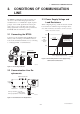
2. CONDITIONS OF COMMUNICATION LINE 2. CONDITIONS OF COMMUNICATION LINE The BRAIN communication signal is superimposed onto the 4 to 20 mA DC analog signal. Since the modulated wave is a communication signal, superimposing it on the normal signal will, from basic principles, cause no error in the DC component of the analog signal. Thus, monitoring can be performed via the BT200 while the transmitter is on-line. 2.
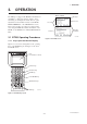
3. OPERATION 3. OPERATION MENU SCREEN The DPharp is equipped with BRAIN communications capabilities, so that range changes, Tag No. setup, monitoring of self-diagnostic results, and zero point adjustment can be handled remotely via the BT200 BRAIN TERMINAL or the CENTUM CS console. This section describes procedures for setting parameters using the BT200. For further information on the BT200, see the BT200 User’s Manual (IM 01C00A1101E).
3. OPERATION 3.1.2 Operating Key Functions Use the function key [F1] CODE to enter symbols. The following symbols will appear in sequence, one at a time, at the cursor each time [F1] CODE is pressed: (1) Alphanumeric Keys and Shift Keys Use the alphanumeric keys in conjunction with the shift keys to enter numbers, symbols, and alphabetic characters. / . – , + * ) ( ’ & % $ # ” ! To enter characters next to these symbols, press [ > ] to move the cursor.
3. OPERATION 3.1.3 Calling Up Menu Addresses Using the Operating Keys UTILITY SCREEN ––WELCOME–– BRAIN TERMINAL ID: BT200 UTILITY 1.ID 2.SECURITY CODE 3.LANGUAGE SELECT 4.LCD CONTRAST 5.PRINTER ADJUST STARTUP SCREEN check connection push ENTER key UTIL FEED esc (UTIL) INITIAL DATA SCREEN PARAM 01:MODEL EJX110A-DM 02:TAG NO. YOKOGAWA 03:SELF CHECK GOOD The utility screen contains the following items. 1. BT200 ID settings 2. Security code settings 3.
3. OPERATION 3.2 Setting Parameters Using the BT200 IMPORTANT After setting and sending data with the BT200, wait 30 seconds before turning off the transmitter. If it is turned off too soon, the settings will not be stored in the transmitter. 3.2.1 Parameter Usage and Selection Before setting a parameter, please see the following table for a summary of how and when each parameter is used. Table 3.2.1 Parameter Usage and Selection Setup item Tag No. setup P.3-6 Description Sets the Tag No.
3. OPERATION 3.2.2 HOME Menu Tree A: DISPLAY B: SENSOR TYPE A10: OUTPUT A11: PRES A15: OUTPUT mA A16: ENGR. OUTPUT A17: ENGR. EXP A20: SP %*1 A21: SP*1 A30: CAPSULE TEMP A60: SELF CHECK B10: MODEL B11: STYLE NO. B20: PRES LRL B21: PRES URL B22: P MIN SPAN B30: SP LRL*1 B31: SP URL*1 B32: SP MIN SPAN*1 B60: SELF CHECK SET C: BASIC SETUP D: AUX SET 1 E: AUX SET2 G: ALARM SET H: AUTO SET I: DISP SET C10: TAG NO.
3. OPERATION 3.2.3 Setting Parameters Set or change the parameters as necessary. After completing these, do not fail to use the “DIAG” key to confirm that “GOOD” is displayed for the selfdiagnostic result at _60: SELF CHECK. set data. The set data items flash. When all items have been confir- print off F2:printer on FEED POFF NO med, press the again. (To go back to the setting panel, press the (NO) key. (1) Tag No. Setup (C10: TAG NO) Use the procedure below to change the Tag No.
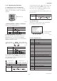
3. OPERATION b. Setting Calibration Range Lower Range Value and Upper Range Value (C21: PRES LRV, C22: PRES URV) These range values are set as specified in the order before the instrument is shipped. Follow the procedure below to change the range. • Example 2: With present settings of 0 to 30 kPa, set the upper range value to 10 kPa. DEL • The measurement span is determined by the upper and lower range limit values.
3. OPERATION (4) Output Mode and Integral Indicator Display Mode Setup (C40: OUTPUT MODE, I20: P DISP MODE) The mode setting for the output signal and the integral indicator can be performed independently. (5) Output Signal Low Cut Mode Setup (D10: LOW CUT, D11: LOW CUT MODE) Low cut mode can be used to stabilize the output signal near the zero point. The low cut point can be set in a range from 0 to 20%, the direct ratio corresponding to the output signal of 4 to 20 mA.
3. OPERATION (6) Integral Indicator Scale Setup The following five displays are available for integral indicators: input pressure*1, % of range, user set scale, input static pressure, and % of static pressure range*1. A cycle of up to four displays can be shown by assigning variables to the parameters I10 to I13: DISP OUT1 to DISP OUT4. The low cut point has hysteresis so that the output around the point is behaved as below figure. Output mode: Linear Low cut mode: Zero Low cut: 20.
3. OPERATION a. Display Selection (I10: DISP OUT1) Select the variable for the parameter I10: DISP OUT1 to display on the integral indicator. Follow the procedure below to change the settings. • Example: Set an engineering unit M. Set M. SET I30:ENGR.UNIT • Example: Change the integral indicator scale from % of range to input pressure display. Use the SET I10:DISP OUT1 PRES % < PRES < PRES % < ENGR.PRES < SP > > > > ESC or Press the M_ key twice to enter the setting.
3. OPERATION d. Setting Static Pressure Unit and Scale (D30: SP UNIT, D33: SP LRV, and D34: SP URV) Static pressure can be displayed in measured input static pressure or in %, independent from the 4-20 mA output signal of measured pressure or differential pressure. These parameters allow the entry of the static pressure unit and scale to be displayed. (9) Impulse Line Connection Orientation Setup (D15: H/L SWAP) This function reverses the impulse line orientation.
3. OPERATION a. Setting Password (D57: NEW PASSWORD) Standard specifications The burnout direction switch is set to HIGH. If a failure occurs, the transmitter outputs a 110% or higher signal. • Example: Set the password to 1234ABCD. Option code /C1 The burnout direction switch is set to LOW. If a failure occurs, a –5% or lower output is generated. Press the 1234ABCD key twice to enter the setting.
3. OPERATION (12) Output Status Setup when a Hardware Error Occurs (D26: ERROR OUT) This parameter allows the setting of the output status when a hardware error occurs. The following selections are available. Output mode “LINEAR” 20 mA (100% display) LRV (a) BURNOUT DIR; Outputs the corresponding values of 110% or –5% of output signals according to the setting by burnout direction switch (BO) on the CPU board. (b) HOLD; Outputs the last value held before the error occurred.
3. OPERATION (15) Sensor Trim Each DPharp EJX series transmitter is factory characterized. Factory characterization is the process of comparing a known pressure input with the output of each transmitter sensor module over the entire pressure and temperature operating range. During the characterization process, this comparison information is stored in the transmitter EEPROM.
3. OPERATION When using BT200, the output signal can be adjusted either in % or pressure unit. The unit can be selected by the parameter J09: ADJ UNIT. Output signal can be changed by displaying parameter A10: OUTPUT for % or J10: OUTPUT for pressure unit. DEL DEL CLR SET J11:P ZERO ADJ 0.00000 kPa FEED NO A11:PRES 0.00000 kPa Press the key twice. ESC The measured pressure is changed to 13.5 kPa. a-3. Using External Zero-adjustment Screw This method permits zero adjustment without the BT200.
3. OPERATION b-1. Auto Sensor Trim b-2. Manual Sensor Trim • Example: For the range of 10 to 30 kPa. • Example: For the range of 10 to 30 kPa. J15: P ZERO DEV = 0.04 kPa J16: P SPAN DEV = 0.03 kPa Setting a lower point Transmitter indicates 9.94 kPa as SET J10:ADJ PRES 9.94000 kPa its output when applying a standard Suppose that a standard pressure of 10 kPa is applied and the value of the parameter of J10: ADJ PRES is 9.94 kPa. Correct for this output error of 0.06 kPa by adding 0.
3. OPERATION c. Sensor Trim for Static Pressure (J21: SP ZERO ADJ, J22: SP SPAN ADJ, J25: SP ZERO DEV, J26: SP SPAN DEV) For the EJX differential transmitters (Except for EJX120A), zeroing and full sensor trim of the static pressure is performed in the same way as with the primary process variable (PV). Note that the static pressure sensor trim should be done only after trimming the PV. (16) Test Output Setup (K10: OUTPUT X %) This feature can be used to output a fixed current for loop checks.
3. OPERATION (18) Process Alarm (G10: P AL MODE, G11: P HI.AL VAL, G12: P LO.AL.VAL) The function is used to display the alarm codes when the input pressure exceeds the specified value within the calibration range. The same is available for the input static pressure and the capsule temperature on the pressure sensor. Refer to table 4.2 Alarm Message Summary for the specific alarm code to be generated. Y 100% INPUT OUTPUT Input pressure in % Characterized value 0% 100% X F0342.
3. OPERATION Example: Status output operation of ON WHEN AL. DETECT NOTE Status output for higher alert value No status output signal has been defined for a CPU failure or hardware error. Use a 4-20 mA signal to indicate a transmitter’s failure. Output (%) 5%* of hysteresis (5 C for heat) Setting value • Example: Set the status output to output an off signal when the input pressure exceeds 75 kPa with its alert mode of HI. AL DETECT.
3. OPERATION (20) Capillary Fill Fluid Density Compensation (E10: T.ZERO CMP, E11: TEMP ZERO) For transmitters with diaphragm seals, this function is used to compensate the zero shift caused by the ambient temperature effect on the capillary tubes. EJX118A L h ( ) Transmitter 0 H The following equation indicates the relationship between the calculated output value and the compensating constant K (%/ C) with the measured ambient temperature at the capsule module.
3. OPERATION (21) Adjustment Information and User Memo Fields (J50: ADJ WHO, J51: ADJ DATE, J52: ADJ LOC, J53: ADJ DESC, M17 to M19: MEMO1 to MEMO3) This feature provides four fields for instrument adjustment information at maintenance: inspection date, inspector, location, and description. Also three user memo fields are provided, each holding up to 16 alphanumeric characters. 3.3 Displaying Data Using the BT200 3.3.1 Displaying Measured Data The BT200 can be used to display measured data.
4. SELF-DIAGNOSTICS 4. SELF-DIAGNOSTICS 4.1 Checking for Problems 4.1.1 • Example 3: Checking the history of the errors Identifying Problems with BT200 The following four areas can be checked. (a) Whether connections are good. (b) Whether BT200 was properly operated. (c) Whether settings were properly entered. (d) History of the errors. See examples below. • Example 1: Connection errors Press the ––WELCOME–– BRAIN TERMINAL ID: BT200 UTIL key. appears, press the key.
4. SELF-DIAGNOSTICS 4.1.2 Checking with Integral Indicator NOTE If an error is detected by running self-diagnostics, an error number is displayed on the integral indicator. If there is more than one error, the error number changes at three-second intervals. See table 4.2 regarding the alarm codes. F0403.EPS Figure 8.5.
4. SELF-DIAGNOSTICS 4.2 Alarms and Countermeasures Table 4.2 Alarm Message Summary Indicator BT200 display Output operation during error Cause None GOOD AL. 01 CAP. ERR 01: P-SENSOR ERR Sensor problem. 01: CT-SENSOR ERR Capsule temperature sensor problem. 01: C-EEPROM ERR Capsule EEPROM problem. 02: AT-SENSOR ERR Amplifier temperature sensor problem. 02: A-EEPROM ERR Amplifier EEPROM problem. AL. 02 AMP. ERR Outputs the signal (Hi or Low) set with parameter D26.
5. PARAMETER SUMMARY 5. PARAMETER SUMMARY *1 Item R/W Content Applicable model Upload data Instruments to which applicable: F: Differential pressure transmitters P: Absolute and gauge pressure transmitters L: Flange mounted differential pressure transmitters No. Parameter name F P L 01 MODEL Model R EJX ● ● ● - 02 TAG No.
5. PARAMETER SUMMARY Parameter name Item R/W Content D AUX SET 1 D35 SP POINT Decimal place of static pressure W 0 to 4 D36 SP DAMPING Damping time constant of SP W 0.00 to 100.00 sec D37 SP SELECT H/L select for static pressure W D40 TEMP UNIT Temperature setting unit D50 QUICK RESP D55 Default value Applicable model F P L Upload data *1 No. Auxiliary setting data 1 1 ● - ● ● 2.
*1 No. Parameter name Item R/W Content J ADJUST J09 ADJ UNIT Pressure adjusting unit select W % or PRES UNIT J10 ADJ PRES Adjustment reference pressure R Unit specified in J09 J11 P ZERO ADJ Automatic zero adjustment W 32000 to 32000, unit specified in J09 J12 P SPAN ADJ Automatic span adjustment W J15 P ZERO DEV Manual zero adjustment J16 P SPAN DEV J20 Default value Applicable model Upload data 5. PARAMETER SUMMARY F P L ● ● ● - ● ● ● - 0.
*1 No. Parameter name Item R/W Content P Record History of errors P10 ERROR REC 1 Last error W See A60 P12 ERROR REC 2 Second recent error W See A60 P14 ERROR REC 3 Third recent error W P16 ERROR REC 4 Forth recent error P60 SELF CHECK Self-diagnostics T CHARACTERIZR Signal characterizer setting T10 S. C. ENABLE T11 NUM OF POINT T20 X START (FIX) T21 Default value Applicable model Upload data 5.
APPENDIX 1. SAFETY INSTRUMENTED SYSTEMS INSTALLATION APPENDIX 1. SAFETY INSTRUMENTED SYSTEMS INSTALLATION WARNING The contents of this appendix are cited from exida.com safety manual on the EJX series pressure transmitters specifically observed for the safety transmitter purpose. When using the EJX for Safety Instrumented Systems (SIS) application, the instructions and procedures in this section must be strictly followed in order to preserve the transmitter for that safety level.
APPENDIX 1. SAFETY INSTRUMENTED SYSTEMS INSTALLATION Table A1.2.5 Proof Testing Testing method Functional test: Tools required Expected outcome Handheld terminal Proof Test Coverage =52% Handheld terminal Proof Test Coverage =99% 1. Follow all Management of Change procedures to bypass logic solvers if necessary. Remarks The output needs to be monitored to assure that the transmitter communicates the correct signal. 2. Execute HART/BRAIN command to send value to high alarm (21.
APPENDIX 1. SAFETY INSTRUMENTED SYSTEMS INSTALLATION A1.2.11 Environmental Limits The environmental limits of the EJX are specified in the user’s manual IM 01C25. A1.2.12 Application Limits The application limits of the EJX are specified in the user’s manual IM 01C25. If the transmitter is used outside of the application limits, the reliability data listed in A1.2.9 becomes invalid. A1.3 Definitions and Abbreviations A1.3.
REVISION RECORD Title: EJX Series BRAIN Communication Type Manual No.: IM 01C25T03-01E Edition Date Page 1st Apr. 2004 – Revised Item 2st Oct. 2004 3-19 3.2.3 (20) Add capillary fill fluid density compensation setting procedure. 3rd Aug. 2009 3-8 3-14 3-18 3.2.3 (5) Add example for hysteresis. 3.2.3 (15) Correct misprint. 3.2.3 (19) Add CAUTION. Add note for hysteresis. New publication REVISION RECORD.