User’s Manual EJX Series HART Communication Type IM 01C25T01-01E IM 01C25T01-01E Yokogawa Electric Corporation 6th Edition
EJX Series HART Communication Type IM 01C25T01-01E 6th Edition Contents 1. Introduction................................................................................................ 1-1 Regarding This Manual................................................................................................. 1-1 2. 3. 1.1 Safe Use of This Product ................................................................................. 1-1 1.2 Warranty.......................................................
ii 4. 3.5.8 Trim Analog Output........................................................................... 3-20 3.5.9 Burst Mode........................................................................................ 3-22 3.5.10 Multidrop Mode................................................................................. 3-22 3.5.11 External Switch Mode....................................................................... 3-23 3.5.12 CPU Failure Burnout Direction and Hardware Write Protect.....
iii A1.3 Appendix 2. A1.2.4 Required Parameter Settings.............................................................A-1 A1.2.5 Proof Testing.......................................................................................A-1 A1.2.6 Repair and Replacement....................................................................A-2 A1.2.7 Startup Time........................................................................................A-2 A1.2.8 Firmware Update...................................
Blank Page
1. 1-1 <1. Introduction> Introduction Thank you for purchasing the DPharp EJX electronic pressure transmitter. EJX pressure transmitters are precisely calibrated at the factory before shipment. To ensure both safety and efficiency, please read this manual carefully before operating the instrument. This manual describes the HART protocol communication functions of the EJX series and explains how to set the parameters for EJX series pressure transmitters using the 275 HART Communicator.
(a) Installation • This instrument may only be installed by an engineer or technician who has an expert knowledge of this device. Operators are not allowed to carry out installation unless they meet this condition. • With high process temperatures, care must be taken not to burn yourself by touching the instrument or its casing. • Never loosen the process connector nuts when the instrument is installed in a process. This can lead to a sudden, explosive release of process fluids.
1.3 <1. Introduction> 1-3 ATEX Documentation This setion is only applicable to the countries in the European Union.
1.4 <1. Introduction> 1-4 Matching of Communicator DD and Instrument DD CAUTION Before using the 275 HART Communicator, make that the device description(DD) installed in the communicator matches that of the instrument that is being set up. To check the DD of the instrument and the HART communicator, follow the steps below. If the correct DD is not installed in the communicator, you must upgrade the DD at an authorized facility.
2. Conditions of Communication Line The HART communication signal is superimposed onto the 4 to 20 mA DC analog signal. Since the modulated wave is a communication signal, superimposing it on the normal signal will, from basic principles, cause no error in the DC component of the analog signal. Thus, monitoring can be performed via the 275 HART Communicator while the transmitter is on-line. 2.1 2-1 <2. Conditions of Communication Line> 2.
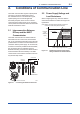
3. 3.1 3-1 <3. Operation> Operation Basic Operation of the 275 HART Communicator 3.1.1 Keys and Functions Communication cable LCD (liquid crystal display) (21 characters×8 lines) Function keys Functions of the keys are indicated on the display. EJX: Process variables 1 Pres 0.000 kPa 2 Pres % 0.00 % 3 AO 4.000 mA 4 SP 0 MPa 5 Static Pres 0.0 % HELP SAVE HOME Pressing (HOME) when the display is as shown changes the display to the Online menu. (See 3.1.2 Display.
3.1.2 Display Function Key Labels The HART communicator searches for a transmitter on the 4 to 20 mA loop when it is turned on. When the HART communicator is connected to the transmitter, the Online menu (Top menu) is started automatically and the following display appears. If no transmitter is found, select the Online menu. Manufacturer’s transmitter type 3-2 <3. Operation> Tag (8 characters) EJX :YOKOGAWA Online 1 Device setup 2 Pres 0.056 kPa 3 AO 4.009 mA 4 LRV 0.
3-3 <3. Operation> 3.1.4 Entering, Setting, and Sending Data Example: Call up the Tag to change the tag number. Check to see where Tag is located in the menu configuration. Then, call up the Tag on the display according to the menu tree (See section 3.3 Menu Tree). Display Operation 1 EJX:YOKOGAWA Online 1 Device setup 2 Pres 3 AO 4 LRV 5 URV DEL SET ESC or ENTER Display 1 appears when the HART Communicator is turned on. Select Device setup.
3.2 Parameter Usage and Selection IMPORTANT Before setting a parameter, please see the following table for a summary of how and when each parameter is used. Table 3.2.1 Memory Unit Range Output mode Damping time constant Output signal low cut mode Display After setting and sending data with the HART communicator, wait 30 seconds before turning off the transmitter. If it is turned off too soon, the settings will not be stored in the transmitter.
Item Monitoring Maintenance Test output HART communicator Pres and Pres % AO Snsr temp SP and SP % Engr Disp/exp/Unit Loop test Diagnostics Self test and Status Output when CPU error has occurred External volume switch Software write protect AO Alm typ Ext SW Write protect Enable wrt 10min Adjustment 3-5 <3. Operation> Zeroing Sensor trim Analog output trim Signal characterizer Capillary fill fluid density compensation New password Zero trim Pres and SP sensor trim D/A trim, Scaled D/A trim S.
3-6 <3. Operation> 3.
<3.
3.4 Basic Setup 3.4.2 Unit 3.4.1 Tag and Device Information To change the Tag No., see section 3.1.4 Entering, Setting, and Sending Data. Up to 8 characters can be set with Tag. The maximum number of characters to be set for other items is as shown below. Item Tag Descriptor Message Date Number of characters 8 16 32 2/2/2 (1) Tag 1. Device setup 3. Basic setup 1. Tag 3-8 <3. Operation> DEL Example: To change the unit from mmH2O to inH2O 1. Device setup 3. Basic setup 2.
<3. Operation> 3.4.3 Range Change The range values are factory-set as specified by the customer. To change the range, follow the steps below. (1) Keypad input — LRV and URV • The measurement span is determined by the upper and lower range values. In this method, the upper and lower range values can be set independently, and the span changes according to the range limit values sent to the transmitter.
<3. Operation> (2) Apply values — changing the ranges while applying an actual Input • This feature allows the lower and upper range values to be setup automatically with the actual input applied. If the upper and lower range values are set, URV and LRV are changed at the same time. Example: To change the range from 0 to 2500 mmH2O to 500 to 3000 mmH2O Call up the Apply values display. 1. Device setup 3. Basic setup 3.
3-11 <3. Operation> 3.4.5 Damping Time Constant Setup 3.4.6 Output Signal Low Cut Mode Setup The damping time constant is set as specified in the order when the instrument is shipped. Follow the procedure below to change the damping time constant. The damping time constant for the amplifier assembly can be set here. The damping time constant for the entire transmitter is the sum of the values for the amplifier assembly and the capsule assembly.
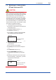
<3. Operation> 3-12 The low cut point has hysteresis so that the output around the point is behaved as below figure. 3.5 Output mode: Linear Low cut mode: Zero Low cut: 20.00% (a) Bi-dir mode enables selection of 50% output at an input of 0 mmH2O. Output Detailed Setup 3.5.1 Bi-directional Flow Measurement Example: If measurement range is 0 to 3000mmH2O (LRV = 0 mmH2O, URV = 3000 mmH2O) Low cut point 1. Device setup 7.2mA (20%) 4.
3-13 <3. Operation> 3.5.2 Integral Indicator Display Mode 3.5.3 Integral Indicator Scale Setup The mode setting for the output signal and the integral indicator can be performed independently. The following five displays are available for integral indicators: input pressure, % of range, user set scale, input static pressure*1, and % of static pressure range*1. A cycle of up to four displays can be shown by assigning variables to the parameters at Disp select.
a. Display Selection d. At Disp select, select the variable that the parameter Disp Out 1 will display on the integral indicator. Example: Change from PRES % to PRES for the display. 1. Device setup 4. Detailed setup 1. Disp select 1. Disp Out 1 1 ESC ENTER 2 EJX:YOKOGAWA Disp select 1 Disp Out 1 2 Disp Out 2 3 Disp Out 3 4 Disp Out 4 HELP SEND PRES Not Used Not Used Not Used HOME (ENTER) Call up the Disp Out 1 display. Select PRES, and press ENTER (F4).
3.5.4 Unit for Displayed Temperature Note that following symbols are not available: # % & < > . * : + The integral indicator shows “-- -- -- -- -- --” when these are entered. Engr LRV and Engr URV are used to set the lower and upper range values for the engineering unit display. When the insrument is shipped, these are set as specified in the order. Example: Set lower range value (LRV) to –50 and upper range value (URV) to 50.
<3. Operation> 3-16 3.5.5 Unit for Displayed Static Pressure 3.5.6 Test Output Follow the procedure to change the static pressure unit. This feature can be used to output a fixed current for loop checks. The available range for test output depends on the settings for the AO lower limit and AO upper limit parameters, whose limit is from 3.6 mA (-2.5%) to 21.6 mA (110%) . Changing this parameter also changes the unit for the static pressure display.
NOTE Test output continues for approximately 10 minutes, then is released automatically. Even if the HART communicator power supply is turned off or the communication cable is disconnected, test output will continue for approximately 10 minutes. 3.5.7 Sensor Trim Each DPharp EJX series transmitter is factory characterized.
a. Auto Sensor Trim 1. Device setup 2. Diag/Service Example: For the range of 1000 to 3000 mmH2O 3. Calibration 1. Device setup 3. Pres sensor trim 2. Diag/Service 2. Pres Trim 3. Calibration 1 EJX:YOKOGAWA Select trim mode 1 Off 2 Auto, Lower Pt 3 Auto, Upper Pt 4 Manual, Lower Pt 5 Manual, Upper Pt ABORT ENTER 3. Pres sensor trim 2. Pres Trim (ENTER) Select the Auto, Lower Pt, and press ENTER (F4). 2 EJX:YOKOGAWA Pres for trim 1383.0 Auto, Lower Pt 0.000000 1350 DEL 3-18 <3.
<3. Operation> b. Manual Sensor Trim 3-19 (3) Sensor Trim for Static Pressure For the EJX differential transmitters, zeroing and full sensor trim of the static pressure is performed in the same way as with the primary process variable (PV). Note that the static pressure sensor trim should be done only after trimming the PV. Example: For the range of 1000 to 3000 mmH2O P LTD = −4.0 mmH2O P UTD = −3.0 mmH2O 1. Device setup 2. Diag/Service 3.
3.5.8 Trim Analog Output 6 Fine current output adjustment is carried out with D/A trim or Scaled D/A trim. • D/A Trim D/A trim is to be carried out if the calibration digital ammeter does not exactly read 4.000 mA and 20.000 mA with an output signal of 0% and 100%. • Scaled D/A Trim Scaled D/A trim is to be carried out if the output is adjusted using a voltmeter or a meter whose scale is 0 to 100%. EJX:YOKOGAWA Fld dev output 4.
8 Example 2: To adjust using a voltmeter EJX:YOKOGAWA Setting fld dev output to 4mA 1. Device setup (OK) 2 Diag/Service HELP 3. Calibration 1 EJX:YOKOGAWA Analog output trim 1 D/A trim 2 Scaled D/A trim 3 Clear D/A trim HOME HELP OK ABORT DEL ‘1 . 0 1’ (ENTER) ABORT ENTER (OK) OK Press OK (F4). HELP DEL (ENTER) ABORT ENTER ABORT ENTER 4 DEL Enter the value read on the meter when the signal is 4 mA.
<3. Operation> 3-22 3.5.9 Burst Mode 3.5.10 Multidrop Mode When the burst mode is set on, the transmitter continuously sends stored data. Either the pressure value, % range/current value, or current/process variables can be selected and sent. The data is sent approximately three times per second as a digital signal when the transmitter is set in burst mode. When data is being sent in burst mode, other operations can be performed with the HART communicator.
3.5.11 External Switch Mode NOTE 1. When the polling option is set as Never Poll or Poll Using Tag, the online menus cannot be called up and displayed. Be sure to select a polling option such as Ask Before Polling. 2. When the same polling address is set for two or more transmitters in multidrop mode, communication with these transmitters is disabled.
<3. Operation> 3.5.12 CPU Failure Burnout Direction and Hardware Write Protect There are two slide switches on the CPU assembly board. One sets the burnout direction at CPU failure, and the other sets a write protection function which disables parameter changes through the use of a handheld terminal or some other communication method.
3-25 <3. Operation> (1) Setting Password Example: Set the password to 1 2 3 4 (2) Entering Password to Enable the Parameter Changes . Example: Enter the password of 1 2 3 4 1 1 EJX: Hot key 1 keypad input 2 Wrt protect menu HELP SEND ESC EJX: Hot key 1 keypad input 2 Wrt protect menu ENTER Press Hot key. Select Wrt protect menu.
3-26 <3. Operation> 3.5.14 Signal Characterizer Example: Set the first coordinates (X1, Y1) as (12, 14) in %. This function is used to compensate the output for non-linear applications. The characterized values are applied to the 4-20 mA output. For the measured pressure, a maximum of nine coordinates can be specified between 0-100%. Perform the coordinate settings while the S.C. at S.C. menu parameter is Disabled. To apply the settings to the output, set the S.C. parameter to Enabled.
3-27 <3. Operation> 3.5.15 Process Alarm The function is used to display the alarm codes when the input pressure exceeds the specified value within the calibration range. The same is available for the input static pressure and the capsule temperature on the pressure sensor. Refer to table 4.3.1 Alarm Message Summary for the specific alarm code to be generated. Example: Set the alert mode from OFF to Hi. Al Detect for the input pressure.
<3. Operation> Example: Status output operation of ON WHEN AL. DETECT Status output for higher alert value Output (%) 5%* of hysteresis (5°C for heat) Setting value 3-28 Example: Set the status output to output an off signal when the input pressure exceeds 75 kPa with the alert mode of Hi. Al Detect. 1. Device setup 4. Detailed setup 3. Output condition 4. Process Alerts 7.
<3. Operation> 3.5.17 Capillary Fill Fluid Density Compensation For transmitters with diaphragm seals, this function is used to compensate the zero shift caused by the ambient temperature effect on the capillary tubes. The following equation indicates the relationship between the calculated output value and the compensating constant K (%/°C) with the measured ambient temperature at the capsule module.
<3. Operation> 3-30 Example: Enter K value obtained from the equation (a). A value haivng up to 3 decimal places may be specified. When h=+3 m, Fill fluid code A, span=15 kPa, K=−(+3)×0.00745÷15×100=−0.149 1. Device setup 4. Detailed setup 2. Signal condition T.Z. Cmp menu 2. Temp Zero 1 ‘ −0.149 ’ EJX: Temp Zero 0.000 %/degC -0.149 HELP ESC DEL ENTER 2 EJX: T.Z. Cmp menu 1 T.Z. Cmp mode 2 Temp Zero HELP SEND On HOME ENTER (ENTER) Enter −0.149 and press ENTER (F4).
4. 4.1 4-1 <4. Diagnostics> Diagnostics Self-Diagnostics Diagnostic by “status” 1. Device setup 4.1.1 Identify Problems by Using the Communicator 2. Diag/Service The HART communicator can be used to run selfdiagnostics on a transmitter and check for incorrect data settings. The Self test and Status commands are available for self-diagnostics.
4.2 Advanced Diagnostics 4.2.1 Multi-sensing Process Monitoring Multi-sensing process monitoring function (option code: /DG6) provides the advanced diagnostics to detect the abnormal conditions in process environment such as an impulse line etc. by using the EJX multisensing technology and its unique algorithm. There are following two functions.
4-3 <4. Diagnostics> Functional block diagram The figure below shows the functional block diagram of ILBD.
4.2.2.1 Blockage Detection Table 4.2.3 shows the default values at the factory setting, which are different according to the model. Limit parameter When the parameter based on pressure fluctuation exceeds the preset value, EJX diagnoses an impulse line as blockage and gives an alarm. The threshold values are set to Limit parameter shown in below table. Table 4.2.
<4. Diagnostics> A/B Blocking Detection 1 “A Blocking” and “B Blocking” indicates the result estimated from blockage degree based on the difference of the high- and low-pressure-side fluctuation values. Ratio fDP, SQRT (fDP / Ref fDP) is used to detect A/B blocking. Ref fDP is the average value of the sum of squares of differential pressure fluctuations under normal condition. BlkF 1 4-5 As the value of Ratio fDP exceeds the value of Lim fDPmax, EJX gives basically an alarm of “A Blocking”.
4-6 <4. Diagnostics> If “Large Fluct L” or “Large Fluct H” is detected, consider whether a blockage result is correct. The threshold values to detect large fluctuation are set to Lim fSPlmax and Lim fSPhmax. Since these values are enough to detect large fluctuation, it is not almost necessary to change them. 4.2.2.
4-7 <4. Diagnostics> 4.2.2.3 Operation Parameters Diag Mode Diag Supp Count (Number of times: 3) An alarm is generated. Diag Mode gives the directive for the ILBD operation. There are following three modes. A B Diag Mode Index Mode 0 Stop 1 2 Calculation Reference Function The blockage detection operation is stopped. The blockage detection operation is performed. Alarms are generated along with the result. Reference values for the blockage detection are obtained and updated to the latest.
4-8 <4. Diagnostics> 4.2.2.4 Operating Procedure If an alarm is often generated or the process condition changed in the ILBD operation, do tuning to change the alarm setting, or to reset the reference values. The basic flow of the ILBD operation is as follows. 1) Initial setting 2) Condition check 3) Start up 4) Perform the ILBD algorithm. Fill out the information to the checklist, at the process shown in below figure.
4.2.2.5 Alarm and Alert Setting The abnormal results as the blockage detection and high/low flange temperature (heat trace monitoring) are given through an analog alert or the LCD display of alarm status. Before performing the ILBD operation, it is necessary to set the alarm and alert according to the following procedure. Storage of Abnormal results (Diag Error) Alarm Masking (Diag Option) Outside Diagnosis Range/ Invalid Ref xx Masking Alarm on Analog Output 4-9 <4.
<4. Diagnostics> 4-10 Diag Fixed Out Val NOTE Use Device description (DD) file for parameter setting. Alarm Masking Diag Option The alarms linked to an analog alert and LCD display are selected by Diag Option. The bit of Diag Option is corresponding to that of Diag Error. The following alarms are set at the factory setting, which is corresponding to hexadecimal 0x08FC.
<4. Diagnostics> NOTE The alarms of “Invalid Ref xx” and “ILBD over range” do not link to the 4-20 mA analog signal and Status output. 4.2.2.6 Condition Check After the EJX differential pressure/pressure transmitter was installed, it is necessary to confirm if Pres is stable under the normal operating condition or if fluctuation amplitude under the normal operating condition is large enough to detect the blockage.
Start of Sampling The sampling of reference value is carried out for 180 sec, which is the default value set to Diag Period. 1) Confirm that the sampling period (Diag Period) is set to 180 sec. 2) Set “Reference” to Diag Mode. The sampling starts soon after the setting. IMPORTANT • For the each parameter, the one value is given. If Reference is set to Diag Mode again, the value is updated and overwritten. • If the power supply is shut down during the sampling, Diag Mode becomes “Stop”.
5) Check also the operation of the analog alert if an analog alert is set. 6) Open the valve completely and check that there are no alarms. Simulation of Both-pressure Side Blockage 1) Close the both-pressure-side valves. 2) Confirm the value of Pres is stable. If not, open the valve a little. 3) Set “Calculation” to Diag Mode so as to start blockage detection operation. 4) Check that an alarm of “B Blocking” is generated after the time that consists of Diag Period and Diag Supp Count passed.
The default values at the factory setting are the values of Lim fDPmax to Lim BlkFmin shown in Figure 4.2.2. Change the threshold value to solve your problem according to the above image. (1) Set “Stop” to Diag Mode. (2) Change the unsuitable value of Limit parameters corresponding to the each blockage detection. Note: Set to “Calculation” after setting the parameter.
<4. Diagnostics> 4-15 4.2.2.12 ILBD Parameter List # Parameter name Default value Expanation 1 Diag Error 0x0000 The results detected by ILBD or Heat trace monitoring are stored into this parameter. Also the condition abnormality in the diagnostic process is stored as an error. 2 Diag Option 0x08FC The masking in this parameter enable to display each error message and the status to the output signal or LCD. The error assigned to each bit is corresponding to that of Diag Error.
# 27 28 29 30 31 32 33 34 35 Parameter name Default value Ref fDP Status Ref fSPl Ref fSPl Status Ref fSPh Ref fSPh Status Ref BlkF Ref BlkF Status Ref DPAvg Ref DPAvg Status 36 Lim fDPmax Refer to Table 4.2.3 37 Lim fDPmin 38 Lim fSPlmax 39 Lim fSPlmin 40 Lim fSPhmax 41 Lim fSPhmin 42 Lim BlkFmax 43 Lim BlkFmin 44 Lim DPAvgmax 45 Lim DPAvgmin 46 Ref Lim fDPmin 7.0E-10 47 Ref Lim fSPmin 1.0E-10 48 Ref Lim BlkFmax 0.
4-17 <4. Diagnostics> 4.2.3 Heat Trace Monitoring The EJX with Heat trace monitoring function calculates the flange temperature by using the two temperature sensors built in the EJX. An analog alert is generated if the temperature reached to the preset level. The flange temperature is based on the following parameters and calculation formula.
4-18 <4. Diagnostics> 4.2.3.2 Out of Temperature Measurement Range When the flange temperature is out of measurement range, the alarm or alert is generated. For the detail of alarm and alert setting, refer to 4.2.2.5. The measurement range is set to Flg temp Hi Alert Val and Flg temp Lo Alert Val, which values can be specified within -50 to 130 deg C. An alarm is generated. Flg temp Hi Alert Flg temp Lo Alert Flg temp Flgtemp An alarm is generated. Time F0415.ai 4.2.3.
4.3 4-19 <4. Diagnostics> Alarms and Countermeasures Table 4.3.1 Integral indicator AL. 01 CAP. ERR Alarm Message Summary HART communicator Cause display P sensor error Sensor problem. CT sensor error Cap EEPROM error AL. 02 AMP. ERR — AT sensor error Amp EEPROM error CPU board error No device ID Capsule temperature sensor problem. Capsule EEPROM problem. Amplifier temperature sensor problem. Amplifier EEPROM problem. Amplifier problem. No device ID is found.
4-20 <4. Diagnostics> Integral indicator AL. 55 SP. ADJ HART communicator display SP SPAN trim err AL. 60 SC. CFG SC config error AL. 79 OV. DISP AL.87 FLG. HI — Cause SP ZERO trim err FT high alarm AL.87 FLG. LO FT low alarm AL.88 INVR.DP Invalid Ref DP AL.88 INVR.SL Invalid Ref SPL AL.88 INVR.SH Invalid Ref SPH AL.88 INVR.F Invalid Ref F AL.89 ILBD.OV AL.89 B BLK AL.89 H BLK AL.89 L BLK AL.89 H LRG ILBD over range AL.89 L LRG Large Fluct L AL.
Table 4.3.2 4-21 <4.
5-1 <5. Parameter Summary> 5. Parameter Summary Function Label Analog output AO alm typ Item Contents Default value Handling Fast key sequences Analog output alarm type High or Low R 1, 4, 3, 2, 5 AO lower limit Lower limit of analog output 3.6000 to 21.6000 mA 3.6000 mA W 1, 4, 3, 2, 7 AO upper limit Upper limit of analog output 3.6000 to 21.6000 mA 21.
5-2 <5.
5-3 <5.
5-4 <5.
5-5 <5. Parameter Summary> Function Static pressure setup Label Item Contents Fast key sequences Absolute WD 1, 4, 1, 2, 7, 4, 1 101.3 kPa WD 1, 4, 1, 2, 7, 4, 2 High WD 1, 4, 1, 2, 7, 5 MD 1, 4, 1, 2, 7, 1, 2 A/G Select Gauge/abs select for static pressure Atm. Pres value Conversion coefficient SP H/L Select H/L select for static pressure High or Low SP Apply values Rerange for static pressure “0%, 100%, or Exit” SP Damp Damping time constant for SP 0.00 to 100.00 sec 2.
A-1 Appendix 1. Safety Instrumented Systems Installation WARNING The contents of this appendix are cited from exida.com safety manual on the EJX series pressure transmitters specifically observed for the safety transmitter purpose. When using the EJX for Safety Instrumented Systems (SIS) application, the instructions and procedures in this section must be strictly followed in order to preserve the transmitter for that safety level. A1.
A-2 Table A1.2.5 Proof Testing Testing method Functional test: 1. Follow all Management of Change procedures to bypass logic solvers if necessary. Tools required • Handheld terminal Expected outcome Remarks Proof Test Coverage The output needs to be =52% monitored to assure that the transmitter communicates the correct signal. • Handheld terminal • Calibrated pressure source Proof Test Coverage =99% 2.
A-3 A1.3 Definitions and Abbreviations A1.3.
A-4 Appendix 2. ILBD Check List Fill out the below checklist according to the operation flow of the ILBD in order to keep the important information for the blockage detection. Checklist (1/5) No. 1 Items 4-20 mA Analog Signal Setting • Select the output mode when an alarm is generaed.
A-5 Checklist (2/5) No. 8 Items Alarm status • Check the alarm status shown in Diag Error. • Check that the alarm status of “ILBD over range” is not shown in Diag Error. 9 ILBD parameters • Record the values of parameters for ILBD operation. • Check the status of parameters for ILBD operation. *: Record the value after checked that the status of each parameter is “GOOD”.
A-6 Checklist (3/5) Go to the following step according to the result of "Invalid Ref xx" shown in the Diag Error of 8th check item. Invalid Ref SPH Diag Error Invalid Ref SPL Invalid Ref DP → → Check item 10-a 10-b : The alarm is generated. : The alarm is not generated. No.
A-7 Checklist (4/5) No. Items 10-a-2 L Side Blocking • Close the low-pressure side valve completely. • Record the values of fDP, fSPl, fSPh, BlkF, and DPAvg after the certain time, (Diag Period X Diag Supp Count), passed. *: Record the value after checked that the status is “GOOD”. • Record the status of Checkbox in Diag Option. • Check that the alarms status of “A Blocking” and “L Side Blocking” are set.
A-8 Checklist (5/5) No. 10-b Items Simulation of Blockage detection operation • Close completely the valve for the side where the alarm of Invalid Reference Value is not generated. For the case that the high-pressure side value is closed; Parameters Result Example fDP* 7.48562E-09 fSPh* 7.14085E-09 fDP* 7.48562E-09 fSPI* 7.23277E-09 • Record the values of fDP, fSPl, fSPh, BlkF, and DPAvg after the certain time, (Diag Period X Diag Supp Count), passed.
Revision Information Title : EJX Series HART Communication Type Manual No. : IM 01C25T01-01E Edition 1st 2nd Date Mar. 2004 Apr. 2004 3rd 4th Oct. 2004 Mar. 2009 5th Aug. 2009 6th Apr. 2010 Page — — 3-26 3-27 3-6 3-11 Revised Item New publication Revise words and phrases 3.5.16 • Add section 3.5.16 Status Output 3.5.17 • Add section 3.5.17 Capillary fill fluid density compensation 3.3 Add Advanced diagnostic parameters. 3.4.6 Add the example of hysteresis is for the cut point.
Blank Page