User’s Manual EJX910A and EJX930A Multivariable Transmitters IM 01C25R01-01E IM 01C25R01-01E 12th Edition
i EJX910A and EJX930A Multivariable Transmitters IM 01C25R01-01E 12th Edition Contents 1. Introduction................................................................................................ 1-1 Regarding This Manual................................................................................................. 1-2 2. 1.1 Safe Use of This Product ................................................................................. 1-2 1.2 Warranty..............................................
ii 5. 6. Installation.................................................................................................. 5-1 5.1 Precautions ....................................................................................................... 5-1 5.2 Mounting ............................................................................................................ 5-1 5.3 Changing the Process Connection.................................................................. 5-2 5.
iii 8. 9. Operation.................................................................................................... 8-1 8.1 Preparation for Starting Operation.................................................................. 8-1 8.2 Zero Point Adjustment...................................................................................... 8-2 Adjusting Zero Point for Differential Pressure.................................... 8-2 8.2.2 Adjusting Zero Point for Static Pressure.......................
1. 1-1 <1. Introduction> Introduction Thank you for purchasing the DPharp EJX multivariable transmitter. Your EJX multivariable Transmitter was precisely calibrated at the factory before shipment. To ensure both safety and efficiency, please read this manual carefully before you operate the instrument. Model EJX910A EJX930A Style code S2 S1 NOTE • This manual mainly describes the hardware configurations of EJX multivariable transmitter.
Regarding This Manual • This manual should be provided to the end user. • The contents of this manual are subject to change without prior notice. • All rights reserved. No part of this manual may be reproduced in any form without Yokogawa’s written permission. • Yokogawa makes no warranty of any kind with regard to this manual, including, but not limited to, implied warranty of merchantability and fitness for a particular purpose.
• When draining condensate from the pressure detector section, take appropriate precautions to prevent the inhalation of harmful vapors and the contact of toxic process fluids with the skin or eyes. • When removing the instrument from a hazardous process, avoid contact with the fluid and the interior of the meter. • All installation shall comply with local installation requirements and the local electrical code.
1.3 <1. Introduction> 1-4 ATEX Documentation This is only applicable to the countries in the European Union.
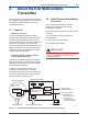
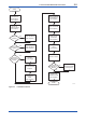
2. About the EJX Multivariable Transmitter This chapter gives an overview of the functions and the installation of the EJX Multivariable transmitter. For details on specific procedures, refer to the corresponding chapter. 2.1 2-1 <2. About the EJX Multivariable Transmitter> Features 2.2 Initial Check and Installation Procedure Figure 2.2 is a flowchart showing the basic sequence for installing and wiring an EJX Multivariable Transmitter.
2-2 <2.
2.3 <2. About the EJX Multivariable Transmitter> Flow Calculation (except Modbus Communication Type) Based Mass Flow Equation Qm = There are two flow calculation modes: auto compensation mode and basic mode. C ε d2 (1–β4) 4 2∆Pρ C, β, ε, d and ρ are dynamically compensated flow factor. The FlowNavigator is required to configure auto compensation mode. (Please refer to IM 01C25R51-01E for FSA120.
2.4.1 Configuration Procedure for Auto Compensation Mode (7) Remove the HART modem from the transmitter. (8) Turn off the power supply. The FlowNavigator is required to configure auto compensation mode. Following shows the procedures for HART protocol type. NOTE (1) Refer to the following instruction manuals for more detailed explanation. Setting with the HART HHT: IM01C25R02-01E. Setting with the Fieldbus configuration tool: IM01C25R03-01E. Setting with the FlowNavigator: IM01C25R51-01E.
Table 2.2 # 1 2 3 4 5 6 7 8 9 10 Symbol Qm Qv Qv_norm Nc Kfactor C ε β d ∆p 11 12 13 14 15 16 17 ρb ρnorm Tb T SPb SP Temp K1 18 K Symbols Table 2.
2-6 <2. About the EJX Multivariable Transmitter> 2.5.1 Configuration Procedure for Basic Mode 2.5.2 Calculation of the Basic mode parameters Either a communicator or the mass flow configuration software is required to carry out configuration in basic mode. There are two methods for the calculation of the Basic mode parameters. Calculation of the basic mode parameters is necessary to perform configuration. Following shows the procedures for HART protocol type.
2-7 <2. About the EJX Multivariable Transmitter> (6) Downloading flow parameter to a transmitter Input Kfactor, Tb, SPb and TempK 1 to the transmitter using either a Communication tool or FlowNavigator. Use the unit of “Kg/m3/degC” for TempK1 IMPORTANT If either the setting of flow unit or differential pressure unit is changed, Kfactor and Nc must be recalculated. Example 1: Calculation of Nc (1) When flow unit is changed. Nc= (Kg/s) /(Mass Flow unit in use) Table 2.
Table 2.8 2-8 <2. About the EJX Multivariable Transmitter> Flow Parameter of Example Description Value Symbol C 0.6043 Discharge coefficient Orifice Corner Taps [ISO5167-1 1991] ReD 1×10⁶ ε 0.984 Expansion factor β=0.6, ∆ρ=50,000 Pa, SP=1,000,000 Pa abs, κ=1.399502 β 0.6 Diameter ratio d 0.03162 m Bore of orifice D 0.0527 m Pipe diameter ρb 1.250380 kg/m3 Base Density on Tb, SPb Condition (NITROGEN 101,325 Pa abs 273.15 K) Tb 273.
<2. About the EJX Multivariable Transmitter> 2-9 Example: Kfactor Calculation Table 2.9 Symbol Qm ∆p Tb SPb T SP Flow Condition Example Value 3011.76 (lb/h) 201.0935 inH2O@68degF 273.15 K 101.325 kPa abs 293.15 K 500 kPa abs Description Differential pressure Reference temperature unit: K Reference static pressure unit: kPa abs Temperature unit: K Static pressure unit: kPa abs Kfactor = Qm(lb/h) / ∆p × (Tb / T) × (SP / SPb) = 3011.76 / 201.0935 × (273.15 / 293.15) × (500 / 101.325) = 99.
3. 3-1 <3. Handling Cautions> Handling Cautions This chapter provides important information on how to handle the transmitter. Read this carefully before using the transmitter. EJX Series transmitters are thoroughly tested at the factory before shipment. When taking delivery of an instrument, visually check them to make sure that no damage occurred during shipment. Also check that all transmitter mounting hardware shown in figure 3.1 is included.
(b) When storing the transmitter, repack it carefully in the packaging that it was originally shipped with. (c) If the transmitter has been used, thoroughly clean the chambers inside the cover flanges, so that there is no process fluid remaining inside. Before placing it in storage, also make sure that the pressure-detector is securely connected to the transmitter section. 3.4 Selecting the Installation Location 3-2 <3. Handling Cautions> 3.
3-3 <3. Handling Cautions> 3.8 Insulation Resistance and Dielectric Strength Test Since the transmitter has undergone insulation resistance and dielectric strength tests at the factory before shipment, normally these tests are not required. If the need arises to conduct these tests, heed the following: (a) Do not perform such tests more frequently than is absolutely necessary. Even test voltages that do not cause visible damage to the insulation may degrade the insulation and reduce safety margins.
<3. Handling Cautions> • Power Supply: 42 V dc max. (HART Communication Type) 9 to 30 V dc, 250 mW (Modbus Communication Type) For FOUNDATION Fieldbus communication type, refer to IM 01C25R03-01E. • Output signal: 4 to 20 mA (HART Communication Type) Modbus (Modbus Communication Type) For FOUNDATION Fieldbus communication type, refer to IM 01C25R03-01E. WARNING Maintaining the safety of explosionproof equipment requires great care during mounting, wiring, and piping.
* –15°C when /HE is specified. • Power Supply: 42 V dc max. (HART Communication Type) 9 to 30 V dc, 250 mW (Modbus Communication Type) For FOUNDATION Fieldbus communication type, refer to IM 01C25R03-01E. • Output signal: 4 to 20 mA (HART Communication Type) Modbus (Modbus Communication Type) For FOUNDATION Fieldbus communication type, refer to IM 01C25R03-01E. Note 2. Wiring • All wiring shall comply with Canadian Electrical Code Part I and Local Electrical Codes.
3.9.3 ATEX Certification ATEX Certification (1) Technical Data a. ATEX Flameproof Type Caution for ATEX flameproof type. Note 1. Model EJX Series pressure transmitters with optional code /KF22 for potentially explosive atmospheres: • No. KEMA 07ATEX0109 X • Applicable Standard: EN 60079-0:2009, EN 60079-1:2007, EN 60079-31:2009 • Type of Protection and Marking Code: Ex d IIC T6...
• Ambient Temperature for gas-proof: –50 to 60°C • Process Temperature (Tp.): 120°C max. • Maximum Surface Temperature for dustproof: T85°C (Tamb.: –40* to 60°C, Tp.: 80°C) T100°C (Tamb.: –40* to 60°C, Tp.: 100°C) T120°C (Tamb.: –40* to 60°C, Tp.: 120°C) * –15°C when /HE is specified. • Enclosure: IP66 and IP67 Note 2.
WARNING To satisfy IP66 or IP67, apply waterproof glands to the electrical connection port. c. ATEX Intrinsically Safe Type/ATEX Flameproof Type/ATEX Type n EJX multivariable transmitters with optional code /KU22 can be selected the type of protection ATEX Intrinsically Safe, Flameproof or ATEX Type n for use in hazardous locations. Note 2. Installation • All wiring shall comply with local installation requirements. (refer to the installation diagram) Note 3.
<3. Handling Cautions> (2) Electrical Connection (6) Name Plate A mark indicating the electrical connection type is stamped near the electrical connection port. These marks are as followed. Screw Size 3-9 Name plate • HART Communication Type Marking ISO M20 × 1.5 female M ANSI 1/2 NPT female N or W • Modbus Communication Type Location of the mark F0307.ai (3) Installation WARNING • All wiring shall comply with local installation requirements and the local electrical code.
<3. Handling Cautions> MODEL: Specified model code. STYLE: Style code SUFFIX: Specified suffix code. SUPPLY: Supply voltage (HART Communication Type) Supply voltage and Power (Modbus Communication Type) For FOUNDATION Fieldbus communication type, refer to IM 01C25R03-01E. OUTPUT: Output signal. MWP: Maximum working pressure. CAL RNG: Specified calibration range. NO.: Serial number and year of production*1. TOKYO 180-8750 JAPAN: The manufacturer name and the address*2.
3.11 Pressure Equipment Directive (PED) (1) General • EJX series pressure transmitters are categorized as piping under the pressure accessories section of directive 97/23/EC, which corresponds to Article 3, Paragraph 3 of PED, denoted as Sound Engineering Practice (SEP). • EJX910A-M, EJX910A-H, EJX930A-M, and EJX930A-H can be used above 200 bar and therefore considered as a part of a pressure retaining vessel where category III, Module H applies.
4. 4-1 <4.
5. 5.1 5-1 <5. Installation> Installation Precautions Vertical pipe mounting Before installing the transmitter, read the cautionary notes in section 3.4, “Selecting the Installation Location.” For additional information on the ambient conditions allowed at the installation location, refer to subsection 10.1 “Standard Specifications.” Transmitter mounting bolt IMPORTANT • When welding piping during construction, take care not to allow welding currents to flow through the transmitter.
5-2 <5. Installation> 5.3 Vertical pipe mounting (Process connector downside) Transmitter mounting bolt Mounting bracket 50 mm(2-inch) pipe U-bolt nut Changing the Process Connection The transmitter is shipped with the process connection specified at the time of ordering. To change the process connection, the drain (vent) plug must be repositioned. To reposition a drain (vent) plug, use a wrench to slowly and gently unscrew it. Then, remove and remount it on the opposite side.
5.4 5-3 <5. Installation> Swapping the High/Lowpressure Side Connection 5.4.1 Rotating Pressure-detector Section 180° This procedure can be applied only to a transmitter with a vertical impulse piping type. The procedure below can be used to turn the pressure detector assembly 180°. Perform this operation in a maintenance shop with the necessary tools laid out and ready for use, and then install the transmitter in the field after making the change. 1) Use an Allen wrench (JIS B4648, nominal 2.
5.5 5-4 <5. Installation> Rotating Transmitter Section The transmitter section can be rotated approximately 360° (180° to either direction or 360° to one direction from the original position at shipment, depending on the configuration of the instrument.) It can be fixed at any angle within above range. 1) Remove the two setscrews that fasten the transmitter section and capsule assembly, using the Allen wrench. 2) Rotate the transmitter section slowly and stop it at designated position.
6. 6.1 6-1 <6. Installing Impulse Piping> Installing Impulse Piping Impulse Piping Installation Precautions The impulse piping that connects the process outputs to the transmitter must convey the process pressure accurately. If, for example, gas collects in a liquid-filled impulse line, or the drain for a gas-filled impulse line becomes plugged, it will not convey the pressure accurately.
4) Now tighten the nuts and bolts securely in the following sequence: Process connector bolts → transmitter-end ball head lock nuts → 3-valve manifold ball head lock nuts → 3-valve manifold mounting bracket U-bolt nuts Impulse piping Nipple Vent plug (optional) 3-valve manifold Stop valve (low pressure side) Equalizing valve (balancing) Ball head lock nut Pipe Pipes Stop valve (high pressure side) Ball head lock nut Nipple 50 mm(2-inch) pipe Process connector Process connector bolts F0602.
(2) Position of Process Pressure Taps and Transmitter If condensate (or gas) accumulates in the impulse piping, it should be removed periodically by opening the drain (or vent) plugs. However, this will generate a transient disturbance in the pressure measurement, and therefore it is necessary to position the taps and route the impulse piping so that any extraneous liquid or gas generated in the leadlines returns naturally to the process piping.
6.2 <6. Installing Impulse Piping> 6-4 Impulse Piping Connection Examples Figure 6.5 shows examples of typical impulse piping connections. Before connecting the transmitter to the process, study the transmitter installation location, the process piping layout, and the characteristics of the process fluid (corrosiveness, toxicity, flammability, etc.), in order to make appropriate changes and additions to the connection configurations. Note the following points when referring to these piping examples.
7-1 <7. Wiring> 7. Wiring 7.1 Wiring Precautions 7.2 IMPORTANT (a) Use stranded leadwires or cables which are the same as or better than 600 V grade PVC insulated wire or its equivalent. (b) Use shielded wires in areas that are susceptible to electrical noise. (c) In areas with higher or lower ambient temperatures, use appropriate wires or cables. (d) In environment where oils, solvents, corrosive gases or liquids may be present, use wires or cables that are resistant to such substances.
7-2 <7. Wiring> (2) Pulse output and Alarm, Status Output 7.4.3 Communicator Connection This instruments uses three wires between the converter and the power supply. Connect the HART Hand Held Terminal (HHT) to the SUPPLY + and – terminals. A DC power and load resistance are required, and pulse output is connected to a totalizer or an electric counter. Transmitter terminal box Power supply + PULSE – SUPP LY Low level of the pulse output is 0 to 2V.
7.5 7-3 <7. Wiring> Wiring (2) Intrinsically Safe Type 7.5.
7-4 <7. Wiring> 7.5.2 Wiring Installation ■ Flameproof metal conduit wiring • A seal fitting must be installed near the terminal box connection port for a sealed construction. • Apply a non-hardening sealant to the threads of the terminal box connection port, flexible metal conduit and seal fitting for waterproofing. (1) General-use Type and Intrinsically Safe Type With the cable wiring, use a metallic conduit or waterproof glands.
7-5 <7. Wiring> PULS E PULS E • Magnified view of the RTD connector in the transmitter's terminal box. SUP PLY SUP PLY K CHEC M ALAR Protection Cap K CHEC M ALAR Connecting Port Procedure (1) Disassemble the cable gland: loosen the running coupler to separate the backnut from the entry. (2) Remove the protection cap over the transmitter electrical connection and install the entry on the electrical connection.
PULS E (6) Turn the running coupler until the seal in the entry comes into contact with the RTD cable. SUPP LY CHECKM ALAR F0720.ai Procedure (1) Disassemble the cable gland: loosen the all parts (2) Remove the protection cap on the RTD electrical connection and RTD connecting port, and screw the adapter body to the RTD electrical connection.
7-7 <7. Wiring> (4) Secure the RTD cable to the packing box by screwing the gland into the packing box at the position where the distance from the connector tip of the RTD cable to the packing box will be 56.5±1mm. Tighten approximately 1 more turn surely after the cable can not move. The quantity of this tightening is very important. It leads to wiring disconnection fault when tighten too much. After that, tighten the clamp nut. 7.6.
7.6.3 Removing Shielded Cable with Cable Gland (External temperature input code: -1, -2, -3, and -4) (1) By pulling out the string attached to the connector, carefully unplug the connector from the transmitter’s connecting port. (2) In the case of using 1/2NPT Type or M20 Type cable gland, remove the running coupler and backnut assembly by turning the running coupler. In the case of using G1/2 Type cable gland, loosen the lock nut screwed into the union cover and remove the union cover.
7.7 <7. Wiring> 7-9 Grounding Grounding is always required for the proper operation of transmitters. Follow the domestic electrical requirements as regulated in each country. For a transmitter with a built-in lightning protector, grounding should satisfy ground resistance of 10Ω or less. PULS E Ground terminals are located on the inside and outside of the terminal box. Either of these terminals may be used. SUPP LY Ground terminal (inside) CHECK ALARM Ground terminal (outside) F0724.
Table 7.2 7-10 <7. Wiring> The connection example for simultaneous analog and pulse and alarm, status output. (For HART protocol type) Output Type Analog Output In this case, Communication is possible (up to a distance of 2km when a CEV cable is used.) Pulse Output In this case, No communication is possible. Description Transmitter Electrical Terminal SUPPLY + PULSE + In this case, No communication is possible.
8. Operation IMPORTANT The information of transmitter configuration in the chapter 8 is specific to HART Communication type. For other Communication type except HART Communication Type, refer to each communication manuals. 8.1 8-1 <8. Operation> Preparation for Starting Operation This section describes the operation procedure for the EJX multivariable transmitter as shown in figure 8.1 (vertical impulse piping type, high-pressure connection: right side) when measuring the liquid flow rate.
■ 8-2 <8. Operation> Confirming that Transmitter is Operating Properly Using the HART communicator • If the wiring system is faulty, ‘No device found at adress O Poll' or communication error’ appears on the display. • If the transmitter is faulty, ‘error message’ appears on the display. Using the integral indicator • If the wiring system is faulty, the display stays blank. • If the transmitter is faulty, an error code is displayed. 8.
The zero-adjustment screw is located inside the cover. Use a slotted screwdriver to turn the zeroadjustment screw. Equalize the transmitter, then turn the screw clockwise to increase the output or counterclockwise to decrease the output. The zero point adjustment can be made with a resolution of 0.01% of the setting range. The degree of zero adjustments varies with the screw turning speed; turn the screw slowly to make a fine adjustment, quickly to make a rough adjustment. 8.2.
8.3 Starting Operation After completing the zero point adjustment, follow the procedures below to start operation. Steps 1) and 2) are specific to the differential pressure transmitters. 1) Close the equalizing valve. 2) Gradually open the low pressure stop valve. This places the transmitter in an operational condition. 3) Confirm the operating status.
<8. Operation> 8-5 8.5.1 Draining Condensate 1) Gradually open the drain screw or drain plug and drain the transmitter pressure-detector section. (See figure 8.4) 2) When all accumulated liquid is completely removed, close the drain screw or drain plug. 3) Tighten the drain screw to a torque of 10 N·m, and the drain plug to a torque of 34 to 39 N·m. Drain plug Drain screw When you loosen the drain screw or drain plug, the accumulated liquid will be expelled in the direction of the arrow. F0805.
9. 9.1 Maintenance Overview 9.3 WARNING Use the procedure below to check instrument operation and accuracy during periodic maintenance or troubleshooting. Since the accumulated process fluid may be toxic or otherwise harmful, take appropriate care to avoid contact with the body or inhalation of vapors when draining condensate or venting gas from the transmitter pressure-detector section and even after dismounting the instrument from the process line for maintenance.
9.3.2 External Temperature (RTD) Using a thermometer resistor as input, calibration of the temperature transmitter is carried out via a 3-core wire connection. As defined the reference resistor value table of the thermometer resistor (RTD), obtain resistance values corresponding to 0, 25, 50, 75 or 100% of the span, and use the obtained resistance as the input value, then deliver it to the temperature transmitter by means of a variable resistor.
<9.
9.4 Disassembly and Reassembly 9.4.1 Replacing the Integral Indicator This section describes procedures for disassembly and reassembly for maintenance and component replacement. Always turn OFF power and shut off and release pressures before disassembly. Use proper tools for all operations. Table 9.2 shows the tools required. Table 9.
9.4.2 Replacing the CPU Board Assembly This subsection describes the procedure for replacing the CPU assembly. (See figure 9.4) ■ Removing the CPU Assembly 1) Remove the cover. If an integral indicator is mounted, refer to subsection 9.4 and remove the indicator. 2) Turn the zero-adjustment screw to the position (where the screw head slot is horizontal) as shown in figure 9.4.
9-6 <9. Maintenance> ■ Removing the Capsule Assembly IMPORTANT Exercise care as follows when cleaning the capsule assembly. • Handle the capsule assembly with care, and be especially careful not to damage or distort the diaphragms that contact the process fluid. • Do not use a chlorinated or acidic solution for cleaning. • Rinse thoroughly with clean water after cleaning. 1) Remove the CPU assembly as shown in subsection 9.4.2.
9-7 <9. Maintenance> 9.4.4 Replacing the Process Connector Gaskets This subsection describes process connector gasket replacement. (See figure 9.6.) (a) Loosen the two bolts, and remove the process connectors. (b) Replace the process connector gaskets. (c) Remount the process connectors. Tighten the bolts securely and uniformly to a torque of 39 to 49 N·m {4 to 5 kgf·m}, and verify that there are no pressure leaks. Bolt Process connector 9.5.
9-8 <9. Maintenance> 9.5.2 Troubleshooting Flowcharts Output travels beyond 0% or 100%. The following sorts of symptoms indicate that transmitter may not be operating properly. Example : • There is no output signal. • Output signal does not change even though process variable is known to be varying. • Output value is inconsistent with value inferred for process variable. Connect a communicator and check self-diagnostics.
9-9 <9. Maintenance> Large output error. (DP, SP or ET) Large output error. (Flow) Connect a communicator and check self-diagnostics. Connect a communicator and check self-diagnostics. Does the selfdiagnostic indicate problem location? NO Refer to error message summary in each communication manual to take actions. NO Is the sensor correctly connected? YES YES NO NO Check the sensor connection and correct it.
9-10 <9. Maintenance> 9.5.3 Alarms and Countermeasures Table 9.3 Integral indicator AL. 01 CAP.ERR Alarm Message Summary (HART protocol type) HART communicator display P sensor error CT sensor error Cap EEPROM error AL. 02 AMP.ERR AT sensor error Amp EEPROM error AL. 03 ET.ERR — CPU board error AD Converter error ET sensor error No device ID Cause Sensor problem. Capsule temperature sensor problem. Capsule EEPROM problem. Amplifier temperature sensor problem. Amplifier EEPROM problem.
Integral indicator AL. 41 F.HI AL. 42 F.LO AL. 35 P.HI AL. 36 P.LO AL. 37 SP.HI HART communicator 4-20mA Output Cause display operation during error F high alarm Input flow exceeds specified Continues to operate and threshold. output. F low alarm P high alarm Input pressure exceeds specified threshold. P low alarm SP high alarm Input static pressure exceeds specified AL. 38 SP.LO SP low alarm threshold. AL. 43 ET.HI 9-11 <9. Maintenance> ET high alarm AL. 44 ET.LO ET low alarm AL. 50 P.
Integral indicator HART communicator display AL.87 FLG. HI FT high alarm AL.87 FLG. LO FT low alarm AL.88 INVR.DP 9-12 <9. Maintenance> Invalid Ref DP Cause Flange temperature exceeds a preset upper limit. Flange temperature is below a preset lower limit. 4-20mA Output operation during error Countermeasure It depends on the Diag Out Option setting. Check the heater failure. Off: Continue to operate and output. Burnout:Outputs AO upper limit or AO lower limit.
10. 10-1 <10. General Specifications> General Specifications 10.1 Standard Specifications Static Pressure (SP) Refer to IM 01C25R03-01E for FOUNDATION Fieldbus communication type marked with“◊”.
10-2 <10. General Specifications> Output specifications for HART Protocol Type “◊” Output Dual output (Both analog and pulse/contact output can be obtained simultaneously). In this case refer to the item “Wiring example for analog output and status/pulse output”. HART Protocol Revision HART protocol revision can be selected from 5 or 7 when ordering. The protocol revision can be changed by user configuration.
<10.
10-4 <10. General Specifications> Mass Flow Calculation Normal Operating Condition: Auto Compensation Mode (FlowNavigator is required for configuration) Ambient Temperature Limits –40 to 85°C (–40 to 185°F) –30 to 80°C (–22 to 176°F) with LCD display (For Measurement function code B of HART and FOUNDATION Fieldbus protocol types) Configuration of the fluid physical properties and primary device for the EJX910A/EJX930A can be performed using a dialog window of FlowNavigator.
<10. General Specifications> Supply & Load Requirements (for HART protocol type) “◊” (Optional features or safety approvals may affect electrical requirements.) With 24 V DC supply, up to a 570 Ω load can be used. See graph below. 600 External load resistance R= E-10.5 0.0244 Digital Communication range 250 R (Ω) 10.5 16.6 25.2 42 Power supply voltage E (V DC) F1003.ai Figure 10.2 Relationship Between Power Supply Voltage and External Load Resistance Supply Voltage “◊” [for HART] 10.
<10. General Specifications> 10-6 Weight [EJX910A] 2.8 kg (6.2 lb) without integral indicator, mounting bracket, process connector and RTD cable. Add 1.5 kg (3.3 lb) for Amplifier housing code 2. [EJX930A] 6.8 kg (14.3 lb) without integral indicator, mounting bracket, process connector and RTD cable. Add 1.5 kg (3.3 lb) for Amplifier housing code 2. Connections Refer to “Model and Suffix Code.
10-7 <10. General Specifications> 10.2 Model and Suffix Codes Model EJX910A Output signal Suffix Codes ......................... -E . . . . . . . . . . . . . . . . . . . . . . . . -J . . . . . . . . . . . . . . . . . . . . . . . . -F . . . . . . . . . . . . . . . . . . . . . . . . -M . . . . . . . . . . . . . . . . . . . . . . . Measurement L . . . . . . . . . . . . . . . . . . . . . M . . . . . . . . . . . . . . . . . . . . . span (capsule) H . . . . . . . . . . . . . . . . . . . . . S . . . .
10-8 <10. General Specifications> Model Suffix Codes EJX930A ......................... Multivariable transmitter Output signal -E . . . . . . . . . . . . . . . . . . . . . . . . -J . . . . . . . . . . . . . . . . . . . . . . . . -F . . . . . . . . . . . . . . . . . . . . . . . . -M . . . . . . . . . . . . . . . . . . . . . . .
Table 10.1 Recommended External Temperature Cable External Temperature Input Code General Application Factory Mutual (FM) Nonincendive Explosionproof Approval Intrinsically safe Approval CENELEC ATEX Type N Flameproof Approval Intrinsically safe Approval Canadian Standards Association (CSA) Explosionproof Approval IECEx Scheme Explosionproof Approval Table. 10.2 10-9 <10.
10-10 <10. General Specifications> 10.3 Optional Specifications Item Factory Mutual (FM) ATEX Description FM Explosionproof *4 Applicable Standard: FM3600, FM3615, FM3810, ANSI/NEMA 250 Explosionproof for Class I, Division 1, Groups B, C and D, Dust-ignitionproof for Class II/III, Division 1, Groups E, F and G, in Hazardous locations, indoors and outdoors (NEMA TYPE 4X) “FACTORY SEALED, CONDUIT SEAL NOT REQUIRED.” Temperature class: T6, Amb. Temp.
10-11 <10. General Specifications> Item Description ATEX Intrinsically safe *1 *3 *4 Applicable standards: EN 60079-0:2009, EN 60079-11:2012, EN 60079-26:2007 Certificate: KEMA 06ATEX0278X II 1G, 2D Ex ia IIC/IIB T4 Ga Ex ia IIIC T85°C, T100°C, T120°C Db Degree of protection: IP66 / IP67 Amb. Temp. for EPL Ga: –40 to 60°C (–40 to 140°F) Amb. Temp. for EPL Db: –30 to 60°C *5 Max. Process Temp. (Tp): 120°C (248°F) Max. Surface Temp. for EPL Db.
10-12 <10. General Specifications> Item Description Painting Color change Coating change 316 SST exterior parts Fluoro-rubber O-ring Lightning protector Code Amplifier cover only P PR Amplifier cover and terminal cover, Munsell 7.5 R4/14 Anti-corrosion coating*1 X2 316 SST name plate, tag plate and zero-adjustment screw*17 All O-rings of amplifier housing. Lower limit of ambient temperature: –15°C(5°F) HART protocol type: Transmitter power supply voltage: 10.
<10.
10-14 <10. General Specifications> 10.4 Dimensions [Model EJX910A] Unit : mm (approx.inch) Conduit connection (for RTD) 116(4.57) 12 (0.47) 39 (1.54) 2-inch pipe (O.D. 60.5 mm) Vent/Drain plugs Conduit connection Electrical connection code 2 and 4 External temp. input code B, C, and D Ground terminal ø70(2.76) High pressure side 54 (2.13) 138(5.43)*2 ø78(3.07) 48 (1.89) 58(2.28) Cable Gland Zero adjustment 110(4.33) Electrical connection code 2 External temp.
Bottom Process Connection Type (Installation code B) 95(3.74) Mounting bracket (optional) Cable Gland Electrical connection code 4 External temp. input code 1, 2, 3, and 4 48 (1.89) Zero adjustment Integral indicator (optional) 2-inch pipe (O.D. 60.5 mm) 110 (4.33) 12 (0.47) 39 (1.54) Shrouding bolt*2 ø70 (2.76) ø78(3.07) Cable Gland 129 (5.08) Conduit connection Conduit connection (for RTD) Electrical connection code 2 External temp. input code 1, 2, 3, and 4 105(4.13) 58(2.28) 188(7.
10-16 <10. General Specifications> [Model EJX930A] 6 (0.24) Unit: mm(approx. inch) 69(2.72) 116(4.57) 54 (2.13) Zero adjustment Ground terminal ø70 (2.76) 192(7.56)*2 105(4.13) 95 (3.74) Vent/Drain plugs ø78(3.07) 52 (2.05) 93 (3.66) Shrouding bolt*5 2-inch pipe (O.D. 60.5 mm) Cable Gland Electrical connection code 2 and 4 External temp. input code B, C, and D Conduit connection Process connector (optional) 132(5.2) 110(4.33) 9 39 (0.35) (1.
<10.
i Revision Information Title : EJX910A and EJX930A Multivariable Transmitters Manual No. : IM 01C25R01-01E Edition Date Page 1st May 2005 — New publication 2nd June 2006 — 1-1 2-7 Add information for FOUNDATION fieldbus protocol type. Add comments for fieldbus in ‘NOTE’ Correct errors in the formula. 2.5.2 Correct errors in Table 2.8 Add WARNING for fieldbus and external temperature input cable. 3.9 Add CENELEC ATEX intrinsically safe type. 3.9.3 Correct errors. 3.
ii Edition Date Page 8th Aug. 2011 1-1, 2-3 and 10-4 2-4 3-9 7-8 10-1 to 10-4 10-5, 10-6, 10-9 and 10-11 9th Mar. 2012 3-3 7-5 to 7-6 10-5 10-6 to 10-7 10-9 to 10-10 10th Aug. 2012 Revised Item 1, 2.3, 2.4, 10.1 Change FSA120 product name. 2.4.1 Change FSA120 product name. 2.5 Correct the Kfactor equation of Basic Mode. 3.9.3 Update explanation of Name Plate. Add the note when using analog and pulse output simultaneously. 7.7 10.1 Corresponds to output siganal code J (HART 5/HART 7 protocol).