User’s Manual DPharp Fieldbus Communication Type (EJXA, EJAE) IM 01C25T02-01E IM 01C25T02-01E 13th Edition
i DPharp Fieldbus Communication Type IM 01C25T02-01E 13th Edition CONTENTS 1. Introduction................................................................................................ 1-1 Regarding This Manual................................................................................................. 1-1 2. 1.1 Safe Use of This Product ................................................................................. 1-2 1.2 Warranty..........................................................
ii 5.2 Network Definition............................................................................................. 5-2 5.3 Definition of Combining Function Blocks....................................................... 5-3 5.4 Setting of Tags and Addresses........................................................................ 5-4 5.5 Communication Setting.................................................................................... 5-4 5.6 6. VCR Setting..................................
iii 8. 9. 10. 7.2.1 Indication of Alarm.............................................................................. 7-1 7.2.2 Alarms and Events.............................................................................. 7-1 7.2.3 Standard categories for NAMUR NE-107 instrument diagnostics alarms................................................................................................. 7-2 7.3 Simulation Function............................................................................
iv A2.4 Integrator......................................................................................................... A2-4 A2.5 Output Process............................................................................................... A2-5 A2.6 A2.7 Appendix 3. A2.5.1 Status Determination........................................................................A2-5 A2.5.2 Determining the Output Value...........................................................A2-6 A2.5.3 Mode Handling . ...
v A5.3 Parameters of PID Block................................................................................ A5-2 A5.4 PID Computation Details................................................................................ A5-4 A5.5 A5.4.1 PV-proportional and -derivative Type PID (I-PD) Control Algorithm ..........................................................................................................A5-4 A5.4.2 PID Control Parameters........................................................
vi A7.4 Software Download Sequence...................................................................... A7-2 A7.5 Download Files................................................................................................ A7-2 A7.6 Steps after Activating a Field Device............................................................ A7-3 A7.7 Troubleshooting.............................................................................................. A7-3 A7.
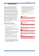
1. 1-1 <1. Introduction> Introduction This manual is for the DPharp EJX/EJA Series Differential Pressure/Pressure Transmitter Fieldbus Communication Type "transmitter". The Fieldbus communication type is based on the same silicon resonant sensing technology used in the BRAIN/HART communication type, and is similar to the communication types in terms of basic performance and operation. This manual describes only those topics that are required for operation of the Fieldbus communication type.
1.1 Safe Use of This Product For the safety of the operator and to protect the instrument and the system, please be sure to follow this manual’s safety instructions when handling this instrument. If these instructions are not heeded, the protection provided by this instrument may be impaired. In this case, Yokogawa cannot guarantee that the instrument can be safely operated.
1.2 <1. Introduction> 1-3 Warranty • The warranty shall cover the period noted on the quotation presented to the purchaser at the time of purchase. Problems occurring during the warranty period shall basically be repaired free of charge. • If any problems are experienced with this instrument, the customer should contact the Yokogawa representative from which this instrument was purchased or the nearest Yokogawa office.
1.3 <1. Introduction> 1-4 ATEX Documentation This is only applicable to the countries in European Union.
2. 2.1 <2. Handling Cautions> 2-1 Handling Cautions Installation of an ExplosionProtected Instrument If a customer makes a repair or modification to an intrinsically safe or explosionproof instrument and the instrument is not restored to its original condition, its intrinsically safe or explosionproof construction may be compromised and the instrument may be hazardous to operate. Please contact Yokogawa before making any repair or modification to an instrument.
b. FM Intrinsically safe and Nonincendive Type The transmitters with optional code /FS15.
Electrical Data: • Rating 1 (Entity) For Groups A, B, C, D, E, F, and G or Group IIC Maximum Input Voltage Vmax: 24 V Maximum Input Current Imax: 250 mA Maximum Input Power Pmax: 1.2 W Maximum Internal Capacitance Ci: 1.76 nF Maximum Internal Inductance Li: 0 mH or • Rating 2 (FISCO) For Groups A, B, C, D, E, F, and G or Group IIC Maximum Input Voltage Vmax: 17.5 V Maximum Input Current Imax: 380 mA Maximum Input Power Pmax: 5.32 W Maximum Internal Capacitance Ci: 1.
2-4 <2. Handling Cautions> HAZARDOUS AREA SAFE AREA Supply Unit and Safety Barrier (FISCO Model) Terminator (FISCO Model) Ex i U U I HandheldTerminal Terminator F0202.ai I.S. fieldbus system complying with FISCO model Installation Diagram for Nonincendive (Division 2 Installation) Terminator + − + − + − SUPPLY Pressure Transmitter Transmitter Note 3. Approved under FNICO Concept. Note 5.
FNICO Rules The FNICO Concept allows the interconnection of nonincendive field wiring apparatus to associated nonincendive field wiring apparatus not specifically examined in such combination.
• WARNING: WHEN AMBIENT TEMPERATURE ≥ 65°C, USE THE HEAT-RESISTING CABLES ≥ 90°C. QUAND LA TEMPÉRATURE AMBIANTE ≥ 65°C, UTILISEZ DES CÂBLES RÉSISTANTES Á LA CHALEUR ≥ 90°C. • Take care not to generate mechanical sparking when accessing to the instrument and peripheral devices in a hazardous location. Note 4.
2-7 <2. Handling Cautions> Note 3. Installation should be in accordance with Canadian Electrical Code Part I and local Electrical Code. Caution for CSA Non-incendive type. (Following contents refer to “DOC. No. ICS018) Note 4. Do not alter drawing without authorization from CSA.
2.1.3 ATEX Certification (1) Technical Data a. ATEX Intrinsically Safe Ex ia Caution for ATEX Intrinsically safe type. Note 1. EJX/EJA-E series pressure transmitters with optional code /KS26 for potentially explosive atmospheres: • No. KEMA 04ATEX1116 X • Applicable Standard: EN 60079-0:2009, EN 60079-11:2007/EN 60079-11:2012, EN 60079-26:2007, EN 60079-27:2008, EN 61241-11:2006 Note 2.
<2. Handling Cautions> b. Note 6. Installation Instructions [Installation Diagram] ATEX Flameproof Type Caution for ATEX flameproof type Terminator + Pressure − SUPPLY Transmitter + − Transmitter + − Transmitter Hazardous Location Terminator 2-9 Non-Hazardous Location − + Safety Barrier + − F0207.ai • In the rating 1(*1), the output current of the barrier must be limited by a resistor ‘Ra’ such that Io = Uo/Ra.
WARNING • Electrostatic charge may cause an exlosion hazard. Avoid any actions that cause the gerenation of eletrostatic charge, such as rubbing with a dry cloth on coating face of the product.
2-11 <2. Handling Cautions> (2) Electrical Connection (6) Name Plate A mark indicating the electrical connection type is stamped near the electrical connection port. These marks are as follows. Name plate Marking Screw Size SUPPLY OUTPUT MWP M ISO M20 × 1.5 female N or ANSI 1/2 NPT female STYLE MODEL SUFFIX W V DC mA DC CAL RNG NO. Made in Japan TOKYO 180-8750 JAPAN : Refer to USER'S MANUAL. Tag plate for flameproof type No. KEMA 07ATEX0109 X Ex d IIC T6...
2.1.4 IECEx Certification a. IECEx Flameproof Type Caution for IECEx flameproof type. Note 1. The transmitters with optional code /SF2 are applicable for use in hazardous locations: • No. IECEx CSA 07.0008 • Applicable Standard: IEC60079-0:2004, IEC60079-1:2003 • Flameproof for Zone 1, Ex d IIC T6...T4 • Enclosure: IP66 and IP67 • Maximum Process Temperature: 120°C (T4), 100°C (T5), 85°C (T6) • Ambient Temperature: –50* to 75°C (T4), –50* to 80°C (T5), –50* to 75°C (T6) * –15°C when /HE is specified.
<2. Handling Cautions> 2-13 Note 3. Installation • In any safety barrier used output current must be limited by a resistor 'R' such that Io=Uo/R. • The safety barrier must be IECEx certified. • Input voltage of the safety barrier must be less than 250 Vrms/Vdc. • The instrument modification or parts replacement by other than authorized representative of Yokogawa Electric Corporation and will void IECEx Intrinsically safe and type n certification.
3. 3.1 About Fieldbus Outline Fieldbus is a widely used bi-directional digital communication protocol for field devices that enable the simultaneous output to many types of data to the process control system. The transmitter of Fieldbus communication type employs the specification standardized by The Fieldbus Foundation, and provides interoperability between Yokogawa devices and those produced by other manufacturers.
4. 4-1 <4. Getting Started> Getting Started Fieldbus is fully dependent upon digital communication protocol and differs in operation from conventional 4 to 20 mA transmission and the BRAIN or HART communication protocol. It is recommended that novice users use field devices in accordance with the procedures described in this section. The procedures assume that field devices will be set up on a bench or in an instrument shop. cross section of 0.
NOTE No CHECK terminal is used for Fieldbus communication transmitter. Do not connect the field indicator and check meter. Before using a Fieldbus configuration tool other than the existing host, confirm it does not affect the loop functionality in which all devices are already installed in operation. Disconnect the relevant control loop from the bus if necessary. Table 4.
4.3 4-3 <4. Getting Started> Bus Power ON 4.3.2 Confirming that Transmitter is Operating Properly 4.3.1 Integral Indicator Display When Powering On Turn on the power of the host and the bus. If the indicator is not lit, check the polarity of the power supply. Turn on the power of the host and the bus. For models with the integral indicator code “D”, the display shows all segments in the LCD and then changes to the displays shown below sequentially.
4.4 Integration of DD Table 4.2 If the host supports DD (Device Description), the DD of the transmitter needs to be installed. Check if host has the following directory under its default DD directory. 594543\000C (594543 is the manufacturer number of Yokogawa Electric Corporation, and 000C is the EJX device number, respectively. The device number of EJA is "0011".) If this directory is not found, the DD of the transmitter has not been included. Create the above directory and copy the DD file (0m0n.
5. <5. Configuration> 5-1 Configuration This chapter describes how to adapt the function and performance of the transmitter to suit specific applications. Because multiple devices are connected to Fieldbus, it is important to carefully consider the device requirements and settings when configuring the system. The following steps must be taken. (1) Network design Determines the devices to be connected to Fieldbus and checks the capacity of the power supply.
5.2 Network Definition 0x00 Before connection of devices with Fieldbus, define the Fieldbus network. Allocate PD Tag and node addresses to all devices (excluding such passive devices as terminators). The PD Tag is the same as the conventional one used for the device. Up to 32 alphanumeric characters may be used for definition. Use a hyphen as a delimiter as required. The node address is used to specify devices for communication purposes.
5.3 Definition of Combining Function Blocks The input/output parameters for function blocks are combined. As required, they can be combined with the input of the control block. The setting is written to the transmitter link object. See “Block setting” in Section 5.6 for the details. It is also possible to read values from the host at proper intervals instead of connecting the transmitter block output to other blocks.
5.4 Setting of Tags and Addresses 5.5 This section describes the steps in the procedure to set PD Tags and node addresses in the transmitter. There are three states of Fieldbus devices as shown in Figure 5.4, and if the state is other than the lowest SM_OPERATIONAL state, no function block is executed. EJX must be transferred to this state when a transmitter tag or address is changed.
Table 5.4 VCR Static Entry SubParameter index 1 FasArTypeAndRole 2 3 4 5-5 <5. Configuration> FasDllLocalAddr FasDllConfigured RemoteAddr FasDllSDAP 5 FasDllMaxConfirm DelayOnConnect 6 FasDllMaxConfirm DelayOnData Description Indicates the type and role of communication (VCR). The following 4 types are used for DPharp. 0x32: Server (Responds to requests from host.) 0x44: Source (Transmits alarm or trend.) 0x66: Publisher (Sends AI block output to other blocks.
Table 5.5 VCR List Index VCR Factory Setting (SM) Number 303 1 For system management (Fixed) 304 2 Server (LocalAddr = 0xF3) 305 3 Server (LocalAddr = 0xF4) 306 4 Server (LocalAddr = 0xF7) 307 5 Trend Source (LocalAddr = 0x07, Remote Address=0x111) 308 6 Publisher for AI1 (LocalAddr = 0x20) 309 7 Alert Source (LocalAddr = 0x07, Remote Address=0x110) 310 8 Server (LocalAddr = 0xF9) 311 9 Publisher for AI2 (LocalAddr = 0x21) 312 to 10 to 35 Not used. 337 5.5.2 Function Block Execution Control Table 5.
5.6.2 Trend Object Table 5.9 It is possible to set the parameter so that the function block automatically transmits Trend. The transmitter has seven Trend objects, six of which are used for Trend in analog mode parameters and one is used for Trend in discrete mode parameter. A single Trend object specifies the trend of one parameter.
Table 5.11 5-8 <5.
Relative Parameter Mnemonic Index 96 97 98 99 100 101 102 103 104 105 106 107 108 109 110 111 112 113 114 115 116 117 118 119 120 121 122 123 Table 5.
Relative Index 42 43 44 45 46 47 48 49 50 51 52 53 54 55 56 57 58 59 60 61 62 63 64 65 66 67 68 69 70 71 72 73 74 75 76 77 78 79 80 81 82 83 84 85 86 87 88 5-10 <5.
Table 5.13 View Object for LCD Transducer Block Relative VIEW VIEW VIEW VIEW Parameter Mnemonic Index 1 2 3 4 1 ST_REV 2 TAG_DESC STRATEGY ALERT_KEY MODE_BLK BLOCK_ERR UPDATE_EVT BLOCK_ALM TRANSDUCER_ DIRECTORY 3 4 5 6 7 8 9 10 11 12 13 14 15 16 17 18 19 20 21 22 23 24 25 26 27 28 29 30 31 32 33 34 35 36 37 38 39 40 41 42 5-11 <5.
Table 5.15 <5.
6. 6.1 Explanation of Basic Items Outline (1) Target (Target mode): Sets the operating condition of the block. (2) Actual (Actual mode): Indicates the current operating condition. (3) Permit (Permitted mode): Indicates the operating condition that the block is allowed to take. (4) Normal (Normal mode): Indicates the operating condition that the block will usually take.
6.3.2 Block Mode The Block modes permitted for the SENSOR transducer block are Automatic (Auto) and Out of Service (O/S). The mode must be set to Auto under normal operating conditions, and to O/S when making changes to an important parameter. For parameters that can only be changed in the Auto and O/S modes, refer to the parameter list for the SENSOR Transducer block in Chapter 9. 6.3.
Diagnosis of adjustment results: Procedure for automatic adjustment The procedure for automatic adjustment is as follows: When the amount of zero adjustment or span adjustment exceeds any of the following adjustment limits, “AL50: Adjustment range error for pressure/ differential pressure” is displayed. (1) Change the Block mode Set MODE_BLK to O/S. The conditions for zero/span adjustment are as follows: (2) Enter zero% pressure Apply the actual zero% pressure to EJX.
Determination of the range limit of static pressure signal: When the static pressure signal exceeds the maximum working pressure (MWP) of the capsule, set the status of PRIMARY_VALUE to UncertainSubnormal. Also, set the status of SECONDARY_ VALUE and TERTIARY_VALUE to UncertainSensor Conversion not Accurate. The status under normal conditions is Good-Non Specific.
6.3.6 BLOCK_ERR BLOCK_ERR presents the cause of an error in the block. The SENSOR transducer block checks the following causes and sets the relevant bits. BLOCK_ERR Bit Error 1 other 7 13 15 Cause Differential pressure adjusted by zero/span adjustment out of measurement range, Static pressure adjusted by zero/span adjustment out of measurement range other Pressure sensor failure, Capsule temperature sensor failure other Electronic circuit failure Out-of-Service MODE_BLK.Target is O/S 6.4.
<6. Explanation of Basic Items> 6-6 6.4.4 Example Displays of the Integral Indicator Example display of AI1 OUT and PID FF_VAL, respectively Display of AI1 OUT (1) Pressure Value Block tag (2) Pressure Value (3) Pressure Value Parameter name Unit (4) Pressure Value Status Display of PID FFVAL (5) Pressure Value Block tag (6) Pressure Value (7) Pressure Value Parameter name Unit (8) Pressure Value Status F0605.
6-7 <6. Explanation of Basic Items> 6.4.5 Procedure to Set the Built-in Display Select from Parameter Displays (1-4) (DISPLAY_SEL) Specify whether DISPLAY1, DISPLAY2, DISPLAY3, or DISPLAY4 should be displayed. Select items to be displayed in the lower text field (INFO_SEL) Specify whether tag, parameter, unit, or status should be displayed.
Table 6.1 <6. Explanation of Basic Items> Parameters to be displayed on LCD Block Name SENSOR TRANSDUCER AI1 AI2 AI3 PID AR IT SC IS 6-8 Parameter PRIMARY_VALUE SECONDARY_VALUE TERTIARY_VALUE CAP_TEMP_VAL AMP_TEMP_VAL FLG_TEMP_VAL* PV PARAMETER_SEL PRIMARY VALUE SECONDARY VALUE TERTIARY VALUE CAP TEMP VALUE AMP TEMP VALUE FLG TEMP VALUE AI1 PV Display PV SP.HI SP.LO CAP.TMP AMP.TMP FLG.
6-9 <6. Explanation of Basic Items> 6.4.
6.5 6-10 <6. Explanation of Basic Items> AI Function Block 6.5.3 IO_OPTS The AI function block is a unit of the software and executed according to the system schedule. During execution, it incorporates data from the SENSOR transducer block. After execution, it updates analog outputs and processes newly generated alarms. AI function blocks can provide a discrete output which shows the status of LO, LO_LO, HI, or HI_HI.
<6. Explanation of Basic Items> 6-11 6.5.5 OUT_D OUT_D.value is “1” when the alarms selected by OUT_D_SEL occur. OUT_D.status is linked OUT.status. OUT_D.value can be written the value form 0 to 15 when block mode is O/S or MAN mode. The OUT_ D_SEL options are shown below. High High Alarm (1): OUT_D.value will be “1” when HI_HI alarm occurs. High Alarm (2): OUT_D.value will be “1” when HI alarm occurs. Low Low Alarm (4): OUT_D.value will be “1” when LO_LO alarm occurs. Low Alarm (8): OUT_D.
7. <7. In-Process Operation> In-Process Operation This chapter describes the procedure performed when changing the operation of the function block of the transmitter in process. 7.1 Mode Transition When the function block mode is changed to Out_Of_Service, the function block pauses and a block alarm is issued. When the function block mode is changed to Manual, the function block suspends updating of output values.
Table 7.1 7.2.3 Standard categories for NAMUR NE107 instrument diagnostics alarms Alert Object Analog Alert Discrete Alert Update Alert Field Diagnostic Alert Subindex 1 1 1 1 2 2 2 2 3 3 3 3 4 4 4 4 5 5 5 5 6 7 6 7 6 7 6 7 8 8 8 9 9 10 10 8 11 11 7-2 <7.
Table7.2 7-3 <7.
7.3 7-4 <7. In-Process Operation> Simulation Function Amplifier Assembly The simulation function simulates the input of a function block and lets it operate as if the data was received from the transducer block. It is possible to conduct testing for the downstream function blocks or alarm processes. A SIMULATE_ENABLE switch is mounted in the transmitter amplifier. This is to prevent the accidental operation of this function. When this is switched on, simulation is enabled. (See Figure 7.2.
Table 7.4 7-5 <7.
8. 8.1 8-1 <8. Device Information> Device Information DEVICE STATUS Device status for the transmitter are indicated by using parameter DEVICE_STATUS_1 to DEVICE_ STATUS_8 (index 1045 to 1052) in Resource Block. Table 8.
Hexadecimal 0x02000000 0x00800000 0x00400000 0x00200000 0x00100000 0x00080000 0x00040000 0x00020000 0x00010000 0x00008000 Table 8.3 Hexadecimal 0x80000000 0x40000000 0x20000000 0x10000000 0x00008000 8-2 <8.
Table 8.5 Hexadecimal 0x80000000 0x40000000 0x20000000 0x10000000 Table 8.6 Hexadecimal 8-3 <8.
Hexadecimal 0x00000200 0x00000100 Display through DD Invalid Ref fSPh (AL-88) Invalid Ref BlkF (AL-88) Description VALUE_FSPH under normal conditions is not up to the reference fluctuation level required to blockage detection. NAMUR NE-107 category C 0x80000000 0x40000000 VALUE_BLKF under normal conditions is not up to the reference fluctuation level required to blockage detection.
8.2 8-5 <8. Device Information> Status of Each Parameter in Failure Mode Following tables summarize the value of EJX parameters when LCD display indicates an Alaram. Table 8.9 ALARM Display Action of each parameters in failure mode related Resource block and Sensor Transducer block Cause of Alarm AL.01 Pressure CAP.ERR Sensor problem Capsule Temperature Sensor problem Capsule memory problem AL.02 Amplifier AMP.ERR Temperature Sensor problem Amplifier memory problem Amplifier problem AL.
Table 8.11 ALARM Display AL.30 HI.HI LO.LO AL.31 HI.HI LO.LO AL.32 HI.HI LO.LO AL.33 HI.HI LO.LO AL.43 AI O/S AL.44 AI O/S AL.45 AI O/S AL.46 NO.SCHD AL.47 NO.SCHD AL.48 NO.SCHD AL.70 PID O/S PID.MAN NO.SCHD AL.71 SC O/S SC MAN NO.SCHD AL.72 IT O/S IT MAN NO.SCHD AL.73 IS O/S IS MAN NO.SCHD AL.74 AR O/S AR MAN NO.SCHD AL.90 AI SML AL.91 AI SML AL.92 AI SML AL.93 AI MAN AL.94 AI MAN AL.95 AI MAN 8-6 <8.
Table 8.12 ALARM Display AL.87 FLG HI AL.87 FLG LO AL.88 INVR.DP AL.88 INVR.SL AL.88 INVR.SH AL.88 INVR.F AL.89 B BLK AL.89 H BLK AL.89 L BLK AL.89 H LRG AL.89 L LRG AL.89 A BLK AL.89 DIAG.OV 8-7 <8. Device Information> Action of each parameters in failure mode related Advanced Diagnostic (option code: /DG1) SENSOR Transducer block DIAG_ERR Cause of Alarm Hexadecimal Display through DD PV.STATUS SV.STATUS TV.STATUS (*1) Flange Temperature High Alarm occurs.
9. 9-1 <9. Parameter Lists> Parameter Lists Note: O/S: MAN: AUTO: The Write Mode column contains the modes in which each parameter is write enabled. Write enabled in O/S mode. Write enabled in Man mode and O/S mode. Write enabled in Auto mode, Man mode, and O/S mode. 9.
<9.
<9.
9-4 <9.
Relative Index Parameter Name Index 119 1119 DEVICE_ CONDITION_ ACTIVE_4 120 1120 DEVICE_ CONDITION_ ACTIVE_5 121 1121 DEVICE_ CONDITION_ ACTIVE_6 122 1122 DEVICE_ CONDITION_ ACTIVE_7 123 1123 DEVICE_ CONDITION_ ACTIVE_8 9.2 9-5 <9.
9-6 <9. Parameter Lists> Relative Index Parameter Name Index 18 2018 CAL_MIN_SPAN Factory Default Write Mode — Minimum span of capsule kPa — Silicon resonant — Range of capsule — Explanation The minimum calibration span value allowed.
<9.
Relative Index 102 103 104 105 106 107 to 137 9.3 Index 2102 2103 2104 2105 2106 2107 to 2137 9-8 <9. Parameter Lists> Parameter Name FLG_TEMP_L_LIM FLG_TEMP_ALM TEST_KEY1 TEST_KEY2 TEST_KEY3 TEST_1 to TEST_31 Factory Default -50 Write Mode — — — — — — Explanation Used for Heat trace monitoring. Refer to A8.3.6. Used for Heat trace monitoring. Refer to A8.3.6. Not used for the transmitter. Not used for the transmitter. Not used for the transmitter. Not used for the transmitter.
<9. Parameter Lists> Relative Index Parameter Name Index 20 2520 EXP_MODE1 Factory Default 0 Write Mode O/S 9-9 Explanation Selection of the displayed value in exponent such as x1, x10, x100, and x1000. Block tag which includes a parameter to be displayed on display2 Selection of a parameter to be displayed on display2. Select a parameter from Table 6.1 Name of block tag to be displayed on display2; up to six alphanumeric plus a slash [/] and a period [.] Selection of unit to be displayed.
<9.
<9. Parameter Lists> Relative Index Index Index Parameter Name Factory Default Index AI1 AI2 AI3 20 4020 4120 4220 UPDATE_EVT — Write Mode — 21 4021 4121 4221 BLOCK_ALM — — 22 4022 4122 4222 ALARM_SUM Enable — 23 4023 4123 4223 ACK_OPTION 0xFFFF AUTO 24 4024 4124 4224 ALARM_HYS 0.
10. 10-1 <10. General Specifications> General Specifications 10.1 Standard Specifications For items other than those described below, refer to each User’s Manual. Applicable Model: All DPharp EJX/EJA series. Output: Digital communication signal based on FOUNDATION Fieldbus protocol. Supply Voltage: 9 to 32 V DC for general use, flameproof type and Type n 9 to 24 V DC for intrinsically safe type Entity model 9 to 17.
10-2 <10. General Specifications> 10.2 Optional Specifications For items other than those described below, refer to each User’s Manual.
A1-1 Appendix 1. Signal Characterizer (SC) Block The Signal Characterizer (SC) block is used to convert the values of input signals according to a line-segment function. The line-segment function is created using 21 points of the X/Y coordinates specified by the user. This function block can also be used as a transmission line for control signals and supports backward control.
Line-segment factor determination section Input section Output section IN_1 IN_2 A1-2 Determining the mode BLOCK_ERR OUT processing Determining the gradient and intercept OUT_1 Y or X Determining the OUT_2 status and computing OUT X or Y CURVE_X CURVE_Y SWAP_2 MODE = AUTO MODE = MAN or O/S FA0102.ai Figure A1.
A1-3 A1.3 Line-segment Factor Determination Section When the mode is AUTO and no bit in BLOCK_ERR is set, the "gradient" and "intercept" of a line passing through two points that are considered line-segment approximation values are determined. A1.3.1 Conditions for Configuring Valid Coefficients (CURVE_X, CURVE_Y) No write error is generated with respect to the settings in CURVE_X and CURVE_Y.
A1-4 Example of the case where SWAP_2 is on (monotone increase): The input range of IN_1 is always in CURVE_X. The following shows the input/output graph of the IN_1 values. Y Output Y6 (High limit) Y1 (Low limit) X1 Figure A1.4 X2 X3 X4 X5 X6 X7 =INFINITY X Input FA0104.ai Example of Curve for IN_1 (SWAP_2 = on) The input range of IN_2 is always in CURVE_Y. The following shows the input/output graph of the IN_2 values.
A1-5 A1.
A1.5 Application Example A1.5.1 Input Compensation The following is an application example of pH compensation made by performing feedback control. The pH is a value representing the degree of acidity or alkalinity and ranges from 0 to 14. pH 7 indicates neutral, a value smaller than 7 represents acidity, and a value larger than 7 denotes alkalinity. It is very difficult to control pH with a quickly changing reaction rate at a point near 7. 14 13 12 11 10 9 8 7 6 5 4 3 2 1 A1-6
A1-7 A1.5.3 Backward Control Line-segment function AI PID OUT IN SC OUT BKCAL_IN IN_1 AO OUT_1 OUT_2 IN_2 CAS_IN BKCAL_OUT 90 80 70 CURVE_Y SC: The controlled variable output from PID is converted into an information quantity that can be interpreted by AO, and backward information from AO is converted into an information quantity that can be interpreted by PID before being transmitted to the PID. 100 60 50 40 30 20 SWAP_2=ON FA0110.
A2-1 Appendix 2. Integrator (IT) Block The Integrator (IT) block adds two main inputs and integrates them for output. The block compares the integrated or accumulated value to TOTAL_SP and PRE_TRIP and generates discrete output signals OUT_ TRIP or OUT_PTRIP when the limits are reached. The output is as represented by the following equation (for counting upward and rate conversion). OUT.
A2-2 A2.2 Input Process Section When executed, the Integrator block first performs input processing in the order of: "Determining input status" → "Converting Rate or Accum" → "Determining the input flow direction" Switching between Convert Rate and Convert Accum is made using bit 0 (for IN_1) or bit 1 (for IN_2) of INTEG_OPTS. INTEG_OPTS is one of the system parameters and should be set by the user.
A2-3 A2.2.3 Converting Accumulation This following describes an example of accumulation conversion. In accumulation conversion, the difference between the value executed previously and the value executed this time is integrated or accumulated. This conversion applies when the output of a function block used as a counter is input to the input process of the Integrator block.
A2-4 A2.3.2 Addition The following three options are available for addition: • TOTAL: Adds two argument values as is. • FORWARD: Adds two argument values, regarding a negative value as "0." • REVERSE: Adds two argument values, regarding a positive value as "0.
Table A2.1 A2-5
A2-6 OUT.Value, OUT_TRIP.Status, and OUT_PTRIP.Status are determined by the ratio of the "Good" integrated values to all integrated values, which is stored in PCT_INCL (0% to 100%). The user must set the threshold value of each status to UNCERT_LIM and GOOD_LIM. The Integrator block determines the status of the output using the three parameters: PCT_INCL, UNCERT_LIM, and GOOD_LIM.
A2-8 When OP_CMD_INT has become "H" and a reset was made, OP_CMD_INT automatically returns to "L." Even if RESET_IN becomes "H," activating a reset, RESET_IN does not automatically return to "L." The RESET_IN setting will not be retained if the power is turned OFF. A2.6.2 Reset Timing All items are reset during execution of the function block. Therefore, the minimum period of a reset is the block execution period.
A2-9 4.) Judging OUT_TRIP and OUT_PTRIP (see A2.5) OUT_TRIP and OUT_PTRIP are judged again on the basis of the cleared integrated values. There are two options relating to a reset: i Confirm reset (bit 8 of INTEG_OPTS) ii Carry (bit 6 of INTEG_OPTS) i Confirm reset (bit 8 of INTEG_OPTS) If this option is enabled, the next reset is rejected until "1" is set to RESET_CONFIRM.
Index 28 Parameter Name INTEG_TYPE Initial Value Write Mode 1 View 2 3 UP_ AUTO(1) 4 1 Integration Type Setting 4 5 6 7 INTEG_OPTS Definition Value Name 1 UP_AUTO 2 3 29 A2-10 0×0004 Description Counts up and is automatically reset when TOTAL_SP is reached. UP_DEM Counts up and is reset as demanded. DN_AUTO Counts down and is automatically reset when "0" is reached. DN_DEM Counts down and is reset as demanded.
Parameter Name Initial Value 39 UPDATE_EVT 40 BLOCK_ALM 41 ACCUM_ TOTAL 1 1 0 0 0 1 1 0 0 0 0.0 Index Write Mode 1 View 2 3 4 A2-11 Definition Indicates event information if an update event occurs. Indicates alarm information if a block alarm occurs.
A3-1 Appendix 3. Input Selector (IS) Block The function of the Input Selector (IS) block is to automatically select one signal from multiple input signals using a specified selection method. The IS block is used for selective control in which one measured quantity is selected from multiple measured quantities to be transmitted to the controller as a controlled variable. This feature is primarily used for temperature control systems. A3.
A3-2 Output Parameters (Computation or Selection Results) OUT : Block output SELECTED : Indicates the input number selected using the alternatives. Other Parameters OUT_RANGE : Sets the OUT range. STATUS_OPTS : Option used to specify the handling of various statuses. SELECT_TYPE : Determines the input selection algorithm. MIN_GOOD : Parameter specifying the minimum required number of inputs with “good” status.
A3-3 A3.2 Input Section A3.2.1 Mode Handling The Input Selector block’s operations are determined by the mode (parameter name: MODE_BLK). The following describes operations in each mode. Supported Mode O/S (Out of Service) Man Role · System-stopped status. · Allows you to make changes to configuration. · If you do not want to output the value and status from IN or if the value or status thus output is not preferable, you can manually transmit the value to OUT.
A3-4 A3.2.2 MIN_GOOD Handling If there is no selectable input or if the number of selectable inputs is less than the value of MIN_GOOD, SELECTED becomes “0.” A case where the number of valid INs is less than the value of MIN_GOOD: SELECTION IN_1 = 23 IN_2 = 34.5 OUT = certain retained value that was output previously IN_3 = 45 IN_4 = 2.34 IN_5 = 23.6 SELECTED = 0 IN_6 = 15.5 IN_7 = 32.5 IN_8 = 27.
A3-5 A3.3 Selection The following processing is performed after completing input processing. If the number of valid inputs is less than the value of MIN_Good, no input selection is made. A3.3.
A3-6 A3.3.2 SELECTION Handling If the value of OP_SELECT is “0,” input selection using SELECT_TYPE is enabled. When SELECT TYPE is “first good” The IS block selects the input with the smallest input number among valid inputs and transmits the value of that input to OUT. The number of the selected input is transmitted to SELECTED. SELECTION IN_1 = 23 IN_2 = 34.5 OUT = 34.5 IN_3 = 45 IN_4 = 2.34 IN_5 = 23.6 SELECTED = 2 IN_6 = 15.5 IN_7 = 32.5 IN_8 = 27.
A3-7 When SELECT TYPE is “Minimum” The IS block selects the input with the minimum value among valid inputs and transmits the value of that input to OUT. The number of the selected input is transmitted to SELECTED. SELECTION IN_1 = 23 IN_2 = 34.5 OUT = 2.34 IN_3 = 45 IN_4 = 2.34 IN_5 = 23.6 SELECTED = 4 IN_6 = 15.5 IN_7 = 32.5 IN_8 = 27.
A3-8 When SELECT TYPE is “Maximum” The IS block selects the input with the maximum value among valid inputs and transmits the value of that input to OUT. The number of the selected input is transmitted to SELECTED. SELECTION IN_1 = 23 IN_2 = 34.5 OUT = 32.5 IN_3 = 45 IN_4 = 2.34 IN_5 = 23.6 SELECTED = 7 IN_6 = 15.5 IN_7 = 32.5 IN_8 = 27.
A3-9 When SELECT TYPE is “Middle” If there is more than one valid input and the number of such input is an odd number, the value of the middle input will be transmitted to OUT. If there is an even number of valid inputs, the average of the middle two inputs is transmitted to OUT. If the average is used for OUT, the block transmits “0” to SELECTED, while it transmits the number of the input used for the middle for other cases.
A3-10 If there is an odd number of valid inputs: SELECTION IN_1 = 23 IN_2 = 34.5 OUT = 23.6 IN_3 = 45 IN_4 = 2.34 IN_5 = 23.6 SELECTED = 5 IN_6 = 15.5 IN_7 = 32.5 IN_8 = 27.4 DISABLE_1 = OFF DISABLE_2 = OFF SELECT_TYPE = Middle STATUS_OPTS MIN_GOOD = 1 DISABLE_3 = OFF DISABLE_4 = OFF DISABLE_5 = OFF DISABLE_6 = OFF DISABLE_7 = OFF DISABLE_8 = ON OP_SELECT = 0 FA0308.ai Figure A3.
A3-11 When SELECT TYPE is “Average” The block calculates the average of the valid inputs and transmits it to OUT. The number of inputs used to calculate its value is indicated in SELECTED. SELECTION IN_1 = 23 IN_2 = 34.5 OUT = 25.48 (IN_1+···+IN_8)/8 = 25.48 IN_3 = 45 IN_4 = 2.34 IN_5 = 23.6 SELECTED = 8 IN_6 = 15.5 IN_7 = 32.5 IN_8 = 27.
A3-12 A3.4 Output Processing A3.4.1 Handling of SELECTED For the value output to SELECTED when OP_SELECT has been selected (that is, not “0”), the number specified by OP_SELECT will be stored as is. However, “0” is stored in the SELECTED in the following cases: 1. If there is no valid input; 2. If the value of MIN_GOOD is greater than the number of valid inputs; 3.
A3-13 A3.4.2 OUT Processing OUT is an output parameter used to send the value selected in the IS block to another function block. The following describes OUT processing. Table A3.
A3-14 A3.4.3 STATUS_OPTS Bit Use Uncertain as Good Description Causes all inputs (OP_SELECT, IN_n, and DISABLE_n) the status of which is “uncertain,” to be handled as “good” (NC) status inputs and the others to be handled as ”bad” status inputs. When the mode is Man, the status of OUT is interpreted as “uncertain.” (This does not apply to SELECTED.) Uncertain if Man mode A3.
A3-16 A3.6 Application Example The following describes the temperature control system of a fixed bed-type reactor. In this case, there are instances where the point showing the maximum temperature changes due to catalytic deterioration, raw material flow, etc. Therefore, a large number of measurement points are provided, and the maximum value obtained among these measurement points is input to the controller to control reactor temperature.
A4-1 Appendix 4. Arithmetic (AR) Block The Arithmetic (AR) block switches two main inputs of different measurement ranges seamlessly and combines the result with three auxiliary inputs through the selected compensation function (10 types) to calculate the output. A4.1 Arithmetic Function Block Schematic The diagram below shows the Arithmetic block schematic.
A4.2 Input Section There are five inputs: IN and IN_LO main inputs and IN_1, IN_2, and IN_3 auxiliary inputs. IN and IN_LO are intended to connect devices with different measurement ranges and allow the use of switching a measurement range by selecting the measuring device. However, because there are slight differences between IN and IN_LO values even when the same item is measured, instantaneous switching causes abrupt changes in the output.
A4.2.3 INPUT_OPTS INPUT_OPTS has an option that handles an input with “uncertain” or “bad” status as a “good” status input. Bit 0 Function Handles IN as a “good” status input if its status is “uncertain.” 1 Handles IN_LO as a “good” status input if its status is “uncertain.” 2 Handles IN_1 as a “good” status input if its status is “uncertain.” 3 Handles IN_1 as a “good” status input if its status is “bad.” 4 Handles IN_2 as a “good” status input if its status is “uncertain.
A4.3 Computation Section A4.3.1 Computing Equations This subsection shows computing equations used in the computation section: 1) Flow compensation (linear) func = PV × f f = (t_1 / t_2) 2) Flow compensation (square root) func = PV × f f = sqrt(t_1 / t_2 / t_3) A4-4 A4.3.2 Compensated Values In computing equations 1) to 5) in A4.3.1, the value “f” is restricted by the COMP_HI_LIM or COMP_ LO_LIM parameter.
A4.4.1 Mode Handling Mode Auto MAN O/S A4.4.2 Status Handling Output OUT = PRE_OUT For OUT, the OUT value in the Auto mode just before change to MAN or O/S is retained. In the Manual mode (including O/S), the value of OUT in the Auto mode just before a change to the Manual mode is held or the value written to OUT is output. If the mode is switched from Manual to Auto, the value of OUT that is linearly changed with respect to the value of PRE_OUT for time set by BAL_TIME is output.
A4-6 A4.
Relative Index 21 22 23 24 25 26 27 28 29 Parameter BIAS_IN_1 GAIN_IN_1 BIAS_IN_2 GAIN_IN_2 BIAS_IN_3 GAIN_IN_3 COMP_HI_ LIM COMP_LO_ LIM ARITH_ TYPE 30 BAL_TIME 31 32 33 BIAS GAIN OUT_HI_ LIM OUT_LO_ LIM UPDATE_ EVT BLOCK_ ALM 34 35 36 Write Valid Mode Range Initial Value 0 0 0 0 0 0 +INF 1 to 10 View 1 2 3 4 4 4 4 4 4 4 4 Description / Remarks IN_1 bias IN_1 gain IN_2 bias IN_2 gain IN_3 bias IN_3 gain High limit of compensation factor f.
A5-1 Appendix 5. PID Block A PID block performs the PID control computation based on the deviation of the measured value (PV) from the setpoint (SV), and is generally used for constant-setpoint and cascaded-setpoint control. A5.1 Function Diagram The figure below depicts the function diagram of a PID block.
A5-2 A5.3 Parameters of PID Block NOTE: In the table below, the Write column shows the modes in which the respective parameters can be written. A blank in the Write column indicates that the corresponding parameter can be written in all modes of the PID block. A dash (-) indicates that the corresponding parameter cannot be written in any mode.
A5.4 PID Computation Details A5.4.1 PV-proportional and -derivative Type PID (I-PD) Control Algorithm For PID control, the PID block employs the PVproportional and PV-derivative type PID control algorithm (referred to as the I-PD control algorithm) in Auto and RCas mode. The I-PD control algorithm ensures control stability against sudden changes in the setpoint, such as when the user enters a new setpoint value.
A5.7 Control Action Bypass The PID control computation can be bypassed so as to set the SP value in the control output OUT as shown below. Setting BYPASS to “On” bypasses the PID control computation. BYPASS OUT Output CAS_IN RCAS_IN Setpoint Control SP IN Filter Feedforward PV FA0502.ai A5.8 Feed-forward Feed-forward is an action to add a compensation output signal FF_VAL to the output of the PID control computation, and is typically used for feedforward control.
Transition Destination Mode RCas* ** ROut* ** In accordance with the SHED_OPT setting * ** Condition 7. If RCas is set in MODE_ BLK.target - AND if neither IN.status (input status) nor RCAS_ IN.status is Bad. 8. If ROut is set in MODE_ BLK.target - AND if ROUT_IN.status (input status) is not Bad. 9. If RCAS_IN.status or ROUT_IN.status is Bad (indicating a computer failure; see Section A5.17.1 for details). NOT Conditions NOT if any one or more of conditions 1 to 3 are met.
A5.12 External-output Tracking External tracking is an action of outputting the value of the remote output TRK_VAL set from outside the PID block, as illustrated in the figure below. External tracking is performed when the block mode is LO. TRK_VAL TRK_SCALE OUT_SCALE TRK_IN_D PID control computation result OUT LO mode FA0504.ai To change the block mode to LO: (1) Select Track Enable in CONTROL_OPTS. (2) Set TRK_IN_D to true.
A5.15 Manual Fallback Manual fallback denotes an action in which a PID block changes mode to Man and suspends the control action. Manual fallback takes place automatically as a means of abnormality handling when the following condition is met: • IN.status is Bad except when the control action bypass is on. To enable the manual fallback action to take place when the above condition is met, Target to Manual if BAD IN must be specified beforehand in STATUS_ OPTS.
NOTE: If a control block is connected as a cascade primary block of the PID block in question, a mode transition of the PID block to Cas occurs in the following sequence due to initialization of the cascade connection: RCas or ROut → Auto → Cas. A5.18 Alarms A5.19 Example of Block Connections AI There are two kinds of alarms generated by a PID block: block and process alarms. OUT A5.18.
A5.20 View Object for PID Function Block Relative VIEW VIEW VIEW VIEW Parameter Mnemonic Index 1 2 3 4 Relative VIEW VIEW VIEW VIEW Parameter Mnemonic Index 1 2 3 4 1 2 3 4 5 6 7 8 9 10 11 12 13 14 15 16 17 18 19 20 21 22 23 24 25 26 27 28 29 30 31 32 33 34 35 36 37 38 39 40 41 42 43 44 45 46 47 48 49 50 51 A5-10
A6-1 Appendix 6. Link Master Functions A6.1 Link Active Scheduler A link active scheduler (LAS) is a deterministic, centralized bus scheduler that can control communications on an H1 fieldbus segment. There is only one LAS on an H1 fieldbus segment. The transmitter supports the following LAS functions. • PN transmission: Identifies a fieldbus device newly connected to the same fieldbus segment. PN is short for Probe Node.
A6-2 A6.3 Transfer of LAS There are two procedures for an LM to become the LAS: • If the LM whose value of [V(ST)×V(TN)] is the smallest on a segment, with the exception of the current LAS, judges that there is no LAS on the segment, in such a case as when the segment has started up or when the current LAS has failed, the LM declares itself as the LAS, then becomes the LAS. (With this procedure, an LM backs up the LAS as shown in the following figure.
A6-3 (2) In the LAS settings of the transmitter, set the values of V(ST), V(MRD), and V(MID) to the same as the respective lowest capability values in all the devices within the segment. An example is shown below.
A6-4 A6.5 LM Parameters A6.5.1 LM Parameter List The tables below show LM parameters.
A6-6 A6.5.2 Descriptions for LM Parameters (4) LiveListStatusArrayVariable The following describes LM parameters of the transmitter. A 32-byte variable, in which each bit represents the status of whether a device on the same segment is live or not. The leading bit corresponds to the device address 0x00, and final bit to 0xFF.
A6-7 (7) CurrentLinkSettingRecord and ConfiguredLinkSettingsRecord (9) PlmeBasicCharacteristics CurrentLinkSettingRecord indicates the bus parameter settings currently used. ConfiguredLinkSettingsRecord indicates the bus parameter settings to be used when the device becomes the LAS. Thus, when a device is the LAS, its CurrentLinkSettingRecord and ConfiguredLinkSettingsRecord have the same values.
A6-8 (12) LinkScheduleActivationVariable (15) Domain Writing the version number of an LAS schedule, which has already been downloaded to the domain, to this parameter causes the corresponding schedule to be executed. On the other hand, writing 0 to this parameter stops execution of the active schedule.
A6-9 Q3. On a segment where the transmitter works as the LAS, another device cannot be connected. How come? A3-1.
A7-1 Appendix 7. Software Download A7.1 Benefits of Software Download A7.3 Preparations for Software Downloading This function enables you to download software to field devices via a FOUNDATION Fieldbus to update their software. Typical uses are to add new features such as function blocks and diagnostics to existing devices, and to optimize existing field devices for your plant.
A7.4 Software Download Sequence CAUTION The flowchart below outlines the software download procedure. Although the time taken for the entire procedure varies depending on the size of the field bus device’s software, it generally take about 20 minutes where there is a one-to-one connection between a fieldbus device and download tool, and longer when multiple field devices are connected to the fieldbus.
A7.6 Steps after Activating a Field Device Table A7.1 When the communication with a field device has recovered after activating the device, check using the download tool that the software revision of the field device has been updated accordingly. The value of SOFT_REV of the resource block indicates the software revision.
A7-4 A7.8 Resource Block’s Parameters Relating to Software Download Table A7.3 Additional Parameters of Resource Block Relative Index Parameter Name Index 53 1053 SOFTDWN_PROTECT Default (Factory Set) 0x01 54 1054 SOFTDWN_FORMAT 0x01 55 1055 SOFTDWN_COUNT 0 — 56 1056 SOFTDWN_ACT_AREA 0 — 57 58 1057 1058 SOFTDWN_MOD_REV SOFTDWN_ERROR Table A7.
A7-5 A7.9 System/Network Management VFD Parameters Relating to Software Download Table A7.5 System/Network Management VFD Parameters Write Mode: R/W = read/write; R = read only Index Parameter (SM) Name 400 DWNLD_ PROPERTY 410 420 430 440 DOMAIN_ DESCRIPTOR DOWNLOAD_ DOMAIN_ HEADER.1 DOWNLOAD_ DOMAIN_ HEADER.
A7-6 A7.10 Comments on System/Network Management VFD Parameters Relating to Software Download IMPORTANT Do not turn off the power to a field device immediately after changing parameter settings. Data writing actions to the EEPROM are dual redandant to ensure reliability. If the power is turned off within 60 seconds after setup, the parameters may revert to the previous settings.
A7-7 (3) DOMAIN_HEADER Sub Element Index 1 Header Version Number 2 Header Size 3 Manufacturer ID Size (Bytes) 2 2 6 4 Device Family 4 5 Device Type 4 6 7 8 9 Device Revision DD Revision Software Revision Software Name 1 1 8 8 10 Domain Name 8 Description Indicates the version number of the header. Indicates the header size. Indicates the value of resource block’s MANUFAC_ID (manufacturer ID) as character string data. Indicates the device family.
A8-1 Appendix 8. Advanced Diagnostics A8.1 Multi-sensing Process Monitoring Multi-sensing process monitoring function (option code: /DG1) provides the advanced diagnostics to detect the abnormal conditions in process environment such as an impulse line etc. by using the EJX multi-sensing technology and its unique algorithm. There are following two functions.
A8-2 Before taking action in response to a blockage alarm, you need to consider the plant operating conditions. Functional block diagram The figure below shows the functional block diagram of ILBD, which is performed in the SENSOR Transducer block.
A8.2.1 Blockage Detection DIAG_LIM DIAG_LIM When the parameter based on pressure fluctuation exceeds the preset value, EJX diagnoses an impulse line as blockage and gives an alarm. The threshold values are set to DIAG_LIM [1] to [8] in the SENSOR Transducer block. TableA8.2 shows the default values at the factory setting, which are different according to the model. NOTE • When ILBD is performed for the first time, use the default value.
A/B Blocking Detection NOTE A single-side impulse line blockage may generate “B blocking” under the condition where the fluctuation amplitude is much different between high- and low-pressure sides. With a transmitter to measure pressure or tank level, “B Blocking” only is detected. H/L Side Blocking Detection EJX differential pressure transmitter enables to detect both-, a high-, or low-pressure-side blockage.
Large Fluctuation Detection When a pump or compressor starts, the large fluctuation is generated as process condition changes rapidly. This phenomenon affects process fluctuation measurement, so correct blockage detection is not performed. If “Large fluctuation of Low Side” or “Large fluctuation of High Side” is detected, consider whether a blockage result is correct. The threshold values to detect large fluctuation are set to DIAG_LIM [3] and [5]. A8-5 A8.2.
A8.2.3 Operating Parameters DIAG_MODE A8-6 DIAG_COUNT(Number of times: 3) An alarm is generated. DIAG_MODE gives the directive for the ILBD operation. There are following three modes. A B DIAG MODE Code Mode 0 Stop 1 2 Function The blockage detection operation is stopped. Calculation The blockage detection operation is performed. Alarms are generated along with the result.
A8-7 A8.2.4 Operating Procedure If an alarm is often generated or the process condition changed in the ILBD operation, you need to do tuning, to change the alarm setting, or to reset the reference values. The basic flow of the ILBD operation is as follows. 1) Initial setting 2) Condition check 3) Start up 4) Perform the ILBD algorithm Fill out the information to the checklist, at the process shown in below figure.
A8-8 A8.2.5 Alarm and Alert Setting DIAG_PRI The abnormal results, as the blockage detection and high/low flange temperature (heat trace monitoring) are given by an analog alert or the LCD display of alarm status. The analog alert or the LCD display of alarm status is set according to the flow shown in below figure. Storage of Abnormal results (STB.DIAG_ERR) Note: The setting of the highest priority is 15. Set to “Calculation” after setting the parameters.
5 6 7 8 9 10 11 12 13 14 15 Low Side Blocking High Side Blocking B Blocking Invalid Ref BlkF Invalid Ref fSPh Invalid Ref fSPl Invalid Ref fDP Outside Diagnosis Range Flg Temp Low Alarm Flg Temp High Alarm Reflect Blockage to PV/SV/TV status FLG_ TEMP_ALM Alarm status DIAG_L_ ALM Bit A8-9 DIAG_H_ ALM 1.000 Outside Diagnosis Range 0.80 Detectable range 0.000 DPAvg -0.
A8.2.5.5 Reflect Blockage to PV/SV/TV Status “Reflect Blockage to PV/SV/TV Status” corresponding to bit 15 in DIAG_OPTION is used to link the alarm to the OUT signal status of PRIMARY_VALUE, SECONDARY_VALUE, and TERTIARY_VALUE. When the ILBD algorithm detects the abnormality, each signal status becomes “UNCERTAIN: Non Specific”. The alarm is linked to the signal status of PV, SV and TV, according to the following procedure. 1) Set "Stop" to DIAG_MODE.
IMPORTANT • If the impulse line is about to be plugged at the time when a reference value is obtained, blockages cannot be detected accurately. The impulse lines on both the high-pressure and low-pressure sides need to be cleaned before a reference value is obtained. • All air bubbles need to be adequately purged before a reference value is obtained. • Reference values must be obtained under operating condition. • Do not obtain the reference values when the BLOCK_MODE of SENSOR Transducer is OOS.
3) Set “Calculation” to DIAG_MODE so as to start blockage detection operation. 4) Check that an alarm of “High Side Blocking” is generated after the time that consists of DIAG_ PERIOD and DIAG_COUNT passed. 5) Check also the operation of the analog alert if an analog alert is set. 6) Open the valve completely and check that there are no alarms. Simulation of Low-pressure-side Blockage 1) Close the low-pressure-side valve. 2) Confirm the value of PRIMARY_VALUE is stable.
Move the threshold toward the white. • It becomes increasingly likely to give an alarm due to the disturbance from environment change. • If flow/differential pressure is below DIAG_LIM [10] or exceeds DIAG_LIM [9], pressure fluctuation is likely too small or too large to detect the blockage. Move the threshold toward the black. • It enables to be insusceptible to disturbance such as environment change and to detect the blockage easier.
A8-14 A8.2.12 ILBD Parameter Lists All the ILBD parameters belong to the SENSOR Transducer block. Note: O/S: MAN: AUTO: The Write Mode column contains the modes in which each parameter is write enabled. Write enabled in O/S mode. Write enabled in Man mode and O/S mode. Write enabled in Auto mode, Man mode, and O/S mode.
Relative Index Parameter Name Index 73 2073 REF_LIM_FDPMIN Factory Default 7.0E-10 Write Mode AUTO 1.0E-10 AUTO 74 2074 REF_LIM_FSPMIN 75 2075 REF_LIM_BLKFMAX 0.5 76 2076 COMP_FLAG 0 AUTO (Compensation) 77 2077 DIAG_LIM Refer to Table A8.
Relative Index Parameter Name Index 92 2092 RATIO_FSPL Factory Default Write Mode — 93 2093 RATIO_FSPH — 94 2094 CRATIO_FDP — 95 2095 NRATIO_FDP — 96 2096 DIAG_APPLICABLE — A8-16 Explanation SQRT (VALUE_FSPL/REFERENCE_FSPL). VALUE_FSPL decreases and this parameter is used to determine whether low-pressure-side is plugged. SQRT (VALUE_FSPH/REFERENCE_FSPH).
A8-17 A8.2.13 Checklist Fill out the below checklist according to the operation flow of the ILBD in order to keep the important information for the blockage detection. Checklist (1/5) No. Items 1 Enable Analog Alert to Be Generated 2 3 • Uncheck the checkbox of “Diag Alm Disable” in ALARM_SUM. Priority Setting of Analog Alert • Enter a value of more than 3 to DIAG_ PRI. (3 is recommended.
A8-18 Checklist (2/5) No. 8 Alarm status Items • Check the alarm status shown in DIAG_ERR. • Check that the alarm status of “Outside Diagnosis Range” is not shown in DIAG_ERR. 9 ILBD parameters • Record the values of parameters for ILBD operation. • Check the status of parameters for ILBD operation. *: Record the value after checked that the status of each parameter is “GOOD”.
A8-19 Checklist (3/5) Go to the following step according to the result of "Invalid Ref xx" shown in the DIAG_ERR of 8th check item. Invalid Ref fSPh DIAG_ERR (Index: F2086) Invalid Ref fSPl Invalid Ref fdP Check item 10-a 10-b : The alarm is generated. : The alarm is not generated. No.
A8-20 Checklist (4/5) No. Items 10-a-2 Low Side Blocking • Close the low-pressure side valve completely. • Record the values of VALUE_# after the certain time, (DIAG_PERIOD × DIAG_COUNT), passed. *: Record the value after checked that the status is “GOOD”. Parameters *: Record the value after checked that the status is “GOOD”. 7.48562e-9 VALUE_FSPL (Index: 2087) * 7.23277e-9 VALUE_FSPH (Index: 2088) 7.14085e-9 VALUE_BLKF (Index: 2089) * -0.
A8-21 Checklist (5/5) No. 10-b Items Simulation of Blockage detection operation • Close completely the valve for the side where the alarm of Invalid Reference Value is not generated. For the case that the high-pressure side valve is closed; • Record the values of VALUE_# after the certain time, (DIAG_PERIOD × DIAG_COUNT), passed. *: Record the value after checked that the status is “GOOD”.
A8.3 Heat Trace Monitoring The EJX with Heat trace monitoring function calculates the flange temperature by using the two temperature sensors built in the EJX. An analog alert is generated if the temperature reached to the preset level. The flange temperature is based on the following parameters and calculation formula. [Calculation formula] FLG_TEMP_VAL(FT) = CT + Cf × (CT - AT) The FLG_TEMP_VAL (FT) is assigned to Process Value (PV) in the AI function block.
A8.3.1 FLG_TEMP_COEF Setting The value calculated according to the following procedure is set to the FLG_TEMP_COEFF. • To enhance the calculation accuracy of the flange temperature, measure the actual flange temperature by using the temperature sensor etc. • Calculate the ratio of the capsule temperature to the capsule temperature minus the amplifier temperature from the two temperature values measured by EJX.
A8-24 A8.3.6 Status Error There are three statuses of “GOOD”, “UNCERTAIN”, and “BAD” for the status of FLG_ TEMP_VAL. The factor that becomes GOOD/UNCERTAIN/BAD is as follows. Good: Normal status Uncertain: Capsule or Amplifier temperature is out of range Bad: • Capsule or Amplifier temperature sensor failure • Capsule or Amplifier EEPROM failure • Resource block or SENSOR Transducer block is in O/S mode A8.3.
i Revision Information Title : Model EJX Series Fieldbus Communication Type Manual No. : IM 01C25T02-01E Edition 1st 2nd Date Aug. 2004 Feb. 2005 3rd June 2005 4th Apr.2006 Page — 2-2 2-2 to 2-4 2-5 10-2 10-2 6-4 6-10 2-1 to 2-5 5-8 9-5 A-37 5th July 2006 6th Oct. 2006 7th Nov. 2007 8th Feb. 2008 2-6 A-61 2-2 4-1 10-2 2-1 2-9 10-2 A-67 — 2-1 to 2-10 9th Aug. 2009 10th Apr. 2010 11th Mar.
ii Edition Date 12th June 2012 Page 2-2 2-5,2-6 13th June 2013 2.1.1 b. 2.1.2 a.,b. 2-7 2.1.2 b. 2-9 2.1.3(1) b. 2-10 2.1.3(1) c. 2-11 4-3 7-2 2.1.3(6) 4.3.1 7.2.3 7-4 10-1,2,3 7.4 10.1,2,3 2-8 to 2-11 9-4 A5-9 2.1.3 9.1 A5.18.1 Revised Item • Change the enclosure code of FM Explosionproof to “NEMA 4X” from “Type 4X”. • Change the enclosure code of CSA Certification to “NEMA 4X, IP66/ IP67”. • Change the electrical data. Ci = 3.52 nF ← 1.