User’s Manual Model PH202G [Style: S3], PH202S [Style: S3] 2-wire Type pH/ORP(Redox) Transmitter IM 12B07D02-01E IM 12B07D02-01E 11th Edition
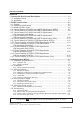
TABLE OF CONTENTS PREFACE 1. Introduction And General Description.............................................................. 1-1 1-1. Instrument check............................................................................................. 1-1 1-2. Application....................................................................................................... 1-3 2. PH202 Specifications ......................................................................................... 2-1 2-1. General .....
4. Operation; Display Functions And Setting ...................................................... 4-1 4-1. Operator interface ........................................................................................... 4-1 4-2. Explanation of operating keys......................................................................... 4-2 4-3. Setting passcodes .......................................................................................... 4-3 4-3-1. Passcode protection ................................
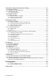
10. Appendix ..................................................................................................... 10-1 10-1. User setting table ........................................................................................ 10-1 10-2. Configuration checklist for PH202G ........................................................... 10-3 10-3. Setup for sensor compatibility..................................................................... 10-4 10-3-1. General ........................................
IM 12B07D02-01E
PREFACE DANGER Electric discharge The EXA analyzer contains devices that can be damaged by electrostatic discharge. When servicing this equipment, please observe proper procedures to prevent such damage. Replacement components should be shipped in conductive packaging. Repair work should be done at grounded workstations using grounded soldering irons and wrist straps to avoid electrostatic discharge.
The following safety symbols are used on the product as well as in this manual. DANGER DANGER This symbol indicates that an operator must follow the instructions laid out in this manual in order to avoid the risks, for the human body, of injury, electric shock, or fatalities. The manual describes what special care the operator must take to avoid such risks.
ATEX Documentation This procedure is only applicable to the countries in European Union. GB All instruction manuals for ATEX Ex related products are available in English, German and French. Should you require Ex related instructions in your local language, you are to contact your nearest Yokogawa office or representative. DK Alle brugervejledninger for produkter relateret til ATEX Ex er tilgængelige på engelsk, tysk og fransk.
SK PL CZ SLO LT H BG LV EST RO M IM 12B07D02-01E
Introduction 1-1 1. INTRODUCTION AND GENERAL DESCRIPTION The Yokogawa EXA 202 is a 2-wire transmitter designed for industrial process monitoring, measurement and control applications. This user’s manual contains the information needed to install, set up, operate and maintain the unit correctly. This manual also includes a basic troubleshooting guide to answer typical user questions. Yokogawa can not be responsible for the performance of the EXA analyzer if these instructions are not followed. 1-1.
1-2 Introduction DISSOLVED OXYGEN TRANSMITTER MODEL SUFFIX SUPPLY OUTPUT AMB.TEMP. MODEL SUFFIX PH202G-F SUPPLY OUTPUT 9 TO 32VDC FF-TYPE113 -10 55°C AMB.TEMP. PH202G-P 9 TO 32VDC PROFIBUS-PA -10 55°C STYLE No. Made in Japan Tokyo 180-8750 JAPAN N200 MODEL SUFFIX SUPPLY FISCO 17.5VDC or 24VDC AMB.TEMP. FISCO field device PH/ORP TRANSMITTER PH202S-F No. IECEx KEM 07.0026X Zone 0 Ex ia IIC T4 IP65 SEE CONTROL DRAWING PH202S-P II 1G SUPPLY FISCO /380mA/5.32W 17.
Introduction 1-3 NOTE: Check that all the parts are present, including mounting hardware, as specified in the option codes at the end of the model number. For a description of the model codes, refer to Chapter 2 of this manual under General Specifications. Basic Parts List: Transmitter PH202 User’s Manual English Optional mounting hardware when specified (See model code) NOTE: mounting screws and special grommet are packed in the terminal compartment, together with a second link for impedance selection.
1-4 Introduction IM 12B07D02-01E
Specification 2-1 2. PH202 Specifications with key diagnostic information available in the display. 2-1. General mA D. Output signal : 4-20 mA loop powered, isolated from input, maximum load 425 Ω at 24 V DC. With the possibility of 21 mA “FAIL” signal (burn up) and 3.6 mA (burn down when HART® or distributor comm. is non-used), 3.9 mA (burn down when HART® or distributor comm. is used). E. Temperature compensation - Range :–30 ºC to 140 ºC (for 8.
2-2 Specification 2-2. Operating specifications A. Performance : pH - Linearity : ±0.01 pH - Repeatability: ±0.01 pH - Accuracy : ±0.01 pH Performance : ORP - Linearity : ±1 mV - Repeatability : ±1 mV - Accuracy : ±1 mV Performance : Temperature with Pt1000 Ω, 3kΩ Balco, 5k1Ω, 350Ω, 6k8Ω, PTC10kΩ & 8k55Ω - Linearity : ±0.3 ˚C - Repeatability: ±0.1 ˚C - Accuracy : ±0.3 ˚C Performance : Temperature with Pt100 Ω - Linearity : ±0.4 ˚C - Repeatability: ±0.1 ˚C - Accuracy : ±0.
Specification 2-3 O. Intrinsically safe Refer to conrol drawings. mA Item Description FM Intrinsically safe Approval Applicable standard: FM3600, FM3610, FM3810 Intrinsically Safe for Class I, Division 1, Groups ABCD Class I, Zone 0, AEx ia IIC Factory Mutual (FM) Temp. Class: T4, Amb. Temp.: -10 to 55°C Intrinsically Safe Apparatus Parameters Vmax=31.5 V, Imax=100 mA, Pmax=1.
2-4 Specification mA NEPSI Certification (PH202S-K) mA mA-HART® communication A. Input : Two wire system 4-20 mA NEPSI Intrinsically Safe Type Cert No. GYJ081156X • Applicable Standard: GB3836.1-2000, GB3836.4-2000 • Type of Protection and Marking Code: Ex ia IIC T4/T6 • Ambient Temperature : T6; –10 to 40°C, T4; –10 to 55°C Note 1 Entity Parameters • Intrinsically safe input parameters (terminal + and -): Maximum Input Voltage (Ui) = 31.
Specification 2-5 PROFIBUS-PA communications A. Input signal: Digital B. Supply voltage: 9 to 32 V DC C. Operating current: 26.0 mA D. Operating values: According to IEC 1158-2 E. Bus connection : Fieldbus interface base on IEC1158-2 according to FISCO-Model F. Power supply: Power supply is achieved dependant on the application by means of segment coupler G. Data transfer: According to PROFIBUS- PA profile class B based on EN 50170 and DIN 19245 part 4 H.
2-6 Specification 2-3. Model and suffix codes 1.
Specification 2-7 2-4. Control Drawing of PH202S mA HART® Specification (IECEx). Intrinsically safe design IEC-Ex standard EX ia IIC : T4 for ambient temp. < 55°C T6 for ambient temp. < 40°C C ertificate nr. IEC Ex KEM 06.0052X PH202S (pH/OR P-transmitter) EX ia or ib C ertified safety barrier or pow er w ith R int=300 : (HAR T compatible) 24 volts D C N ominal Supply V oltage. + + _ SENSOR (S) term inals 11-17 _ Uo = 31.
2-8 Specification 2-5. Control Drawing of PH202S mA HART® Specification (ATEX) Intrinsically safe design C EN ELEC standard EEX ia IIC : T4 for ambient temp. < 55°C T6 for ambient temp. < 40°C C ertificate nr. KEM A 06ATEX 0218 X PH202S (pH/O R P-transmitter) EEx ia or ib C ertified safety barrier or pow er w ith R int=300 : (HAR T compatible) 24 volts D C N ominal Supply V oltage.
Specification 2-9 2-6. Control Drawing of PH202S mA HART® Specification (FM Intrinsically safe design) Intrinsically safe design FM Class I, Div.1, Group ABCD, T4 for ambient temp. < 55°C T6 for ambient temp. < 40°C PH202S transmitter FM Approved safety barrier or power supply with Rint = 300 : (HART compatible) 24 volts DC Nominal Supply Voltage. + + _ - G Sensor(s) For electrical data: see text below. terminals 11-17 Max. cablelength: 60 mtr. Cable dia. : 3…12 mm.
2-10 Specification 2-7. Control Drawing of PH202S mA HART® Specification (FM Non-incendive design). N o n in c e n d iv e d e s ig n F M C la s s I, D iv .2 , G ro u p A B C D , T 4 fo r a m b ie n t te m p . < 5 5 ° C T 6 fo r a m b ie n t te m p . < 4 0 ° C F M A p p ro ve d p o w e r s u p p ly V o c ≦ 3 1 .5 V D C P H 2 0 2 S tra n s m itte r + + _ - G S e n s o r (s ) F o r e le c t r ic a l d a t a : s e e t e x t b e lo w . te rm in a ls 1 1 -1 7 M a x . c a b le le n g th : 6 0 m tr .
Specification 2-11 2-8. Control Drawing of PH202S mA HART® Specification (CSA). Intrinsically safe design C SA Ex ia C lass I, D iv.1, G roup A B C D T4 for am bient temp. < 55°C T6 for am bient temp. < 40°C PH 202S (pH /O R P-transm itter) C S A certified safety barrier or pow er supply (H A R T com patible) 24 volts D C N ominal Supply V oltage. + + _ Sen sor(s) term in als 1 1 -1 7 _ G S uitable values are: V m ax = 31.5 V o ltD C Imax = 100 mA Fo r electrical data: see text belo w .
2-12 Specification 2-9. Control Drawing of PH202S FF/PB Specification (IECEx) Ex ia IIC T4 for ambient temp. d 55 qC Ui = 24 V or Ui = 17,5 V Ii = 250 mA Ii = 380 mA Pi = 1,2 W Pi = 5,32 W PH202S-F or PH202S-P + Safe area Apparatus + - I.S. interface Sensor Connections - I.S. certified Term inator I.S. certified Term inator + - Transm itter Safe area + - Transm itter Zone 0 or 1 Hazardous area x x Sensor(s) are of a passive type to be regarded as 'simple apparatus'.
Specification 2-13 2-10. Control Drawing of PH202S FF/PB Specification (ATEX) Ex ia IIC T4 for ambient temp. d 55 qC Ui = 24 V or Ui = 17,5 V Ii = 250 mA Ii = 380 mA Pi = 1,2 W Pi = 5,32 W PH202S-F or PH202S-P + Safe area Apparatus + - I.S. interface Sensor Connections - I.S. certified Terminator I.S. certified Terminator + - Transmitter Safe area + - Transmitter Zone 0 or 1 Hazardous area x Sensor(s) are of a passive type to be regarded as 'simple apparatus'.
2-14 Specification 2-11. Control Drawing of PH202S FF/PB Specification (FM Intrinsically safe Entity). FM Class I, DIV. 1, Group ABCD T4 for ambient temp. d 55 qC Sensor Connections Max. cablelength: 60 mtr. Cable dia. : 3…12 mm. PH202S-F or PH202S-P + FM Approved barrier Voc (Vt) d 24 V Ioc (It) d 250 mA Poc (Pt) d 1.2 W Ca t 220pF+ Ccable La t 0 H + Lcable + - Sensor Connections - I.S. certified Terminator I.S.
Specification 2-15 WARNING - Substitution of components may impair Intrinsic Safety - To prevent ignition of flammable or combustible atmospheres, disconnect power before servicing or read, understand and adhere to the manufacturer ’s live maintenance procedures.
2-16 Specification 2-12. Control Drawing of PH202S FF/PB Specification (FM Intrinsically safe FISCO) FM Class I, DIV. 1, Group ABCD T4 for ambient temp. d 55 qC Sensor Connections Max. cablelength: 60 mtr. Cable dia. : 3…12 mm. Sensor Connections PH202S-F or PH202S-P + FM Approved FISCO barrier Voc (Vt) d17,5 V Ioc (It) d380 mA Poc (Pt) d5,32 W + - - FM Approved Terminator R = 90..100Ω C = 0..2,2 μF FM Approved Terminator R = 90..100Ω C = 0..
Specification 2-17 x In each I.S. Fieldbus segment only one active source, normally the FM Approved FISCO barrier, is allowed to provide the necessary power for the Fieldbus system. All other equipment connected to the bus cable has to be passive (not providing energy to the system), except to a leakage current of 50μA for each connected device. Seperately powered equipment needs a galvanic isolation to insure that the I.S. Fieldbus circuit remains passive.
2-18 Specification 2-13. Control Drawing of PH202S FF/PB Specification (FM Non-incendive Entity). FM Class I, DIV. 2, Group ABCD T4 for ambient temp. d 55 qC T6 for ambient temp. d 40 qC Sensor Connections Max. cablelength: 60 mtr. Cable dia.: 3…12 mm. Sensor Connections PH202S-B or PH202S-D + FM Approved Power Supply Voc d 32 VDC - FM Approved Terminator R = 90..100Ω C = 0..2,2 μF + - FM Approved Terminator R = 90..100Ω C = 0..
Specification 2-19 2-14. Control Drawing of PH202S FF/PB Specification (FM Non-incendive FNICO) FM Class I, DIV. 2, Group ABCD T4 for ambient temp. d 55 qC T6 for ambient temp. d 40 qC Sensor Connections Max. cablelength: 60 mtr. Cable dia.: 3…12 mm. Sensor Connections PH202S-B or PH202S-D FM Approved Power Supply Voc d 32 VDC + - + - FM Approved Terminator R = 90..100Ω C = 0..2,2 μF FM Approved Terminator R = 90..100Ω C = 0..
2-20 Specification 2-15. Control Drawing of PH202S FF/PB Specification (CSA). CSA Ex ia Class I, DIV. 1, Group ABCD T4 for ambient temp. d 55 qC Ui = 24 V Ii = 250 mA Pi = 1,2 W or Ui = 17,5 V Ii = 380 mA Pi = 5,32 W PH202S-F or PH202S-P + Safe area Apparatus + - I.S. interface Sensor Connections - I.S. certified Terminator I.S.
Installation and wiring 3-1 3. INSTALLATION AND WIRING 3-1. Installation and dimensions 3-1-1. Installation site The EXA transmitter is weatherproof and can be installed inside or outside. It should, however, be installed as close as possible to the sensor to avoid long cable runs between sensor and transmitter. In any case, the cable length should not exceed 50 meters (162 feet).
3-2 Installation and wiring Unit: mm (inch) 18.5 (0.72) +1 0 +1 0 SPACING PANEL CUTOUT PANEL CUTOUT 3.5 (0.14) Unit: mm (inch) Fig. 3-2b. Panel mounting using two (2) self-tapping screws Pipe mounting (Vertical) 56 (2.20) Pipe mounting (Horizontal) 2-Ø6.5 (0.26) 200 (7.87) 4-Ø10 (0.4) 77 (3) 115 70 (4.5) (2.75) Nominal 50 A (O.D. Ø60.5 mm) (2 inch pipe) 4.eps Figure 3-3. Wall and pipe mounting diagram Figure 3-4.
Installation and wiring 3-3 3-2. Preparation Refer to figure 3-4. The power/output connections and the sensor connections should be made in accordance with the diagram on page 3-6. The terminals are of a plug in style for ease of mounting. To 1. 2. 3. 4. open the EXA 202 for wiring: Loosen the four frontplate screws and remove the cover. The terminal strip is now visible. Connect the power supply. Use the gland on the left for this cable. Connect the sensor input, using the gland on the right (see fig.
3-4 Installation and wiring Hand Held Communicator HOLD TEMP.MAN. F AIL MODE pH YES NO ENT > NO > YES MEASURE AUT.CAL MAN.CAL DISPLAY TEMP HOLD MODE ENT YOKOGAWA Computer Sensors Output/supply Input Distributor 0 12 100 180 Recorder CURRENT OUTPUT 2 , 5 or 10 m Safety Barrier PH202S only ref pH/ORP emp. Figure 3-6. System configuration 3-3. Wiring of sensors 3-3-1.
Installation and wiring 3-5 3-3-3. Installation in: Hazardous Area-Non-Incendive The EXA PH202S-N may be installed in a Category 3/ Zone 2/ Div.2 area without the use of safety barriers. Maximum permissible supply voltage 31.5V 3-3-4. Liquid earth In all circumstances, the sensor side of the measuring loop must be grounded to the measuring liquid. The EXA PH202S uses advanced differential high impedance input circuits. This technique calls for a grounding to the liquid.
3-6 Installation and wiring 3-4-2. Connection of the power supply The terminal strip is accessed as was described in §3-2-1. Use the left-hand gland to insert the supply/ output cable to the transmitter. Connect the supply to the terminals marked +, - and G as is indicated in figures 3-8 and 3-9. 3-4-3. Switching the instrument on After all connections are made and checked, the power can be switched on from the distributor. Observe the correct activation of the instrument at the display.
Installation and wiring 3-7 3-5. Wiring the sensor system 3-5-1. Impedance measurement jumper settings NOTE: It is important to decide first which application and which settings are appropriate for the installation. This decision is best made before the jumpers are installed, because the cables will rest beside the jumpers in their installed positions. Table 3-1. Impedance measuring jumpers Figure no.
3-8 Installation and wiring Figure 3-9. Terminal identification labels 3-6. Sensor wiring Refer to figure 3-10, which includes drawings that outline sensor wiring. For sensor wiring of PH8EFP, PH8ERP, PH8EHP, OR8EFG, OR8ERG, HA405, HA406, HA485, DPA405, DPA406, DPA485, HF405, DPAS405, DPAS485 and FU20, see APPENDIX 2 (Chapter 11). The EXA analyzers can be used with a wide range of commercially available sensor types, both from Yokogawa and other manufacturers.
Installation and wiring 3-9 3-6-1. Connection cable There are two types of connection cable, one for single sensors and one for combined sensors. The former is a coaxial cable and has only two connections.
3-10 Installation and wiring Yellow * Red* Red Black Red Blue Blue 11 12 13 14 15 16 17 Temperature Temperature Reference Solution ground Metal (measure) Shield Shield * Cable markers Separate electrodes ORP/REF electrode 11 12 13 14 15 16 17 Temperature Temperature Reference Solution ground(ORP) pH Shield Blue Blue* Red White 11 12 13 14 15 16 17 Temperature Temperature Reference Solution ground Metal (measure) Shield Shield * Cable markers Combined ORP/pH electrode Notes 1.
Installation and wiring 3-11 3-6-3. Sensor cable connections using junction box (BA10) and extension cable (WF10) For the WTB10 terminal box, see APPENDIX. Where a convenient installation is not possible using the standard cables between sensors and transmitter, a junction box and extension cable may be used. The Yokogawa BA10 junction box and the WF10 extension cable should be used.
3-12 Installation and wiring Extension cable may be purchased in bulk quantities, cut to length. Then it is necessary to terminate the cable as shown below. Termination procedure for WF10 cable. 1. Slide 3 cm of heat shrink tube (9 x 1.5) over the cable end to be terminated. 2. Strip 9 cm of the outer (black) insulating material, taking care not to cut or damage internal cores. 3 cm 9 cm heat shrink remove insulation Fig. 3-12a. 3.
Operation 4-1 4. OPERATION; DISPLAY FUNCTIONS AND SETTING 4-1. Operator interface This section provides an overview of the operation of the EXA operator interface. The basic procedures for obtaining access to the three levels of operation are described briefly. For a step-by-step guide to data entry, refer to the relevant section of this user’s manual. Figure 4-1 shows the EXA operator interface. LEVEL 1: Maintenance These functions are accessible by pushbutton through a flexible front cover window.
4-2 Operation Output hold flag Manual temperature compensation flag Fail flag Menu pointer flags Units HOLD Main display TEMP.MAN. FAIL MODE pH Commissioning function menu mV Message display YES NO ENT Key prompt flags Selection keys YES : Accept setting NO : Change setting YES Adjustment keys > : Choose digit to adjust ^ : Adjust digit ENT : Confirm change NO MEASURE AUT.CAL MAN.
Operation 4-3 4-3. Setting passcodes 4-3-1. Passcode protection In Service Code 52, EXA users can set passcode protection for each one of the three operating levels, or for any one or two of the three levels. This procedure should be completed after the initial commissioning (setup) of the instrument. The passcodes should then be recorded safely for future reference.
4-4 Operation 4-5. Display functions 4-5-1. Display functions pH (default) pH MEASURE AUT.CAL MAN.CAL DISPLAY TEMP. HOLD MODE Display Access pH pH AUT.CAL YES NO YES NO (See Auto calibration Chapter 6) NO DISPLAY NO DISPLAY YES Impedance of input 1 NO pH pH YES YES MAN.CAL NO (See Manual calibration Chapter 6) YES Impedance of input 2 NO NO pH pH YES YES (See Sample calibration Software release number Chapter 6) MAN.
Operation 4-5 4-5-2. Display functions pH (ORP) Service Code 01 Set for pH. Service Code 02 Set for ORP on parameter 2. pH MEASURE AUT.CAL MAN.CAL DISPLAY TEMP. HOLD MODE pH "Logbook Scrolling" Logbook data is available only in instruments with "PIN" for advanced function The display can give information about calibrations performed with date and time. The example below shows Asymmetry Potential. pH YES NO AUT.CAL YES NO YES DISPLAY NO NO pH pH YES NO YES MAN.
4-6 Operation 4-5-3. Display functions pH (rH) Service Code 01 Set for pH. Service Code 02 Set to rH on parameter 2. pH pH MEASURE AUT.CAL MAN.CAL DISPLAY TEMP. HOLD YES DISPLAY NO MODE pH YES pH See Auto Cal Chapter 6 YES AUT.CAL YES NO Temp Display NO rH Display NO DISPLAY NO NO pH pH YES YES NO See Man Cal Chapter 6 MAN.
Parameter setting 5-1 5. PARAMETER SETTING 5-1. Maintenance mode Standard operation of the EXA instrument involves use of the maintenance (or operating) mode to set up some of the parameters. Access to the maintenance mode is available via the six keys that can be pressed through the flexible window in the instrument cover. Press the MODE-key once to enter this dialog mode. Note: At this stage the user will be prompted for pass code where this has been previously set up in service code 52 in chapter 5.
5-2 Parameter setting 5-1-1. Manual temperature selection and adjustment pH selected in service code 01. MODE FAIL pH Measure YES NO OUTPUT SET HOLD SERVICE MODE ENT YOKOGAWA MODE pH AUT.CAL YES NO NO NO NO NO pH pH pH YES YES NO YES NO YES NO NO TEMP. YES TEMP.MAN.
Parameter setting 5-3 5-1-2. Process temperature measuring in ORP mode ORP selected in service code 01. MODE mV MEASURE YES NO OUTPUT SET HOLD SERVICE MODE ENT YOKOGAWA MODE mV YES NO MAN.CAL NO NO NO YES YES mV YES NO mV NO YES NO YES NO mV YES NO TEMP. NO Display return to measuring mode with temperature reading.
5-4 Parameter setting mA 5-1-3. Manual activation of HOLD MODE pH MEASURE OUTPUT SET HOLD SERVICE YES NO MODE ENT YOKOGAWA MODE HOLD NO pH pH AUT.CAL YES YES NO NO NO NO NO NO NO YES HOLD pH pH pH YES YES MEASURE YES NO YES NO Note: The HOLD feature must first be activated in the commissioning mode section 5-2-2.
Parameter setting 5-5 5-1-4. Manual impedance check Note: The manual impedance start is available when the sensor impedance measurement is enabled in Service Code 3 and 4. This enables the impedance data to be updated immediately after a maintenance event (e.g.replacing an electrode). MODE pH MEASURE OUTPUT SET HOLD SERVICE YES NO MODE ENT YOKOGAWA MODE pH AUT.
5-6 Parameter setting 5-2. Commissioning mode In order to obtain peak performance from the EXA, you must set it up for each custom application. mA Output range (*OUTP) mA output is set as default to 0 - 14 pH. mA Hold (*HOLD) The EXA transmitter has the ability to “hold” the output during maintenance periods. This parameter should be set up to hold the last measured value, or a fixed value to suit the process.
Parameter setting 5-7 mA 5-2-1. Output range MODE pH pH MEASURE AUT.CAL MAN.CAL DISPLAY TEMP HOLD YES NO OUTPUT SET HOLD SERVICE ENT MODE ENT YOKOGAWA pH ENT Note: When rH or ORP is enabled in codes 02 and 31, the output range is set in a similar way to pH.
5-8 Parameter setting mA 5-2-2. Hold MODE pH MEASURE AUT.CAL MAN.CAL DISPLAY TEMP HOLD YES NO OUTPUT SET HOLD SERVICE MODE ENT YOKOGAWA YES NO NO YES YES YES YES NO NO NO NO YES YES NO HOLD deactivated, return to commissioning menu. YES NO NO YES NO HOLD HOLD YES NO YES YES IM12B07D02-01E NO HOLD active last measured value.
Parameter setting 5-9 HOLD value set, return to commissioning menu.
5-10 Parameter setting 5-2-3. Service 12B6C3 29 Service MODE pH MEASURE AUT.CAL MAN.CAL DISPLAY TEMP HOLD YES NO OUTPUT SET HOLD SERVICE MODE ENT Example: Service Code 01 Select main parameter YOKOGAWA for pH for ORP > With the >, ,ENT keys ENT ENT Waitscreen screen is Wait is displayed displayed brieflybefore before returning briefly returning to to commissionning menu. commissioning menu.
Parameter setting 5-11 5-3. Notes for guidance in the use of service coded settings Don't set or input service code numbers other than the code numbers defined in this manual. Setting an undefined service code may make the transmitter malfunction. When an undefined service code is input by some accident, push the MODE key and escape from the service level. 5-3-1. Parameter specific functions Code 01 *pH/ORP Choose the main measuring parameter.
5-12 Parameter setting Code Display Function Parameter specific functions Function detail 01 *PH.ORP Select main parameter pH 02 *PRM.2 Enable 2nd parameter Off ORP 03 *Z1.CHK *Z.L.xΩ Impedance check 1 X Y Z 0 1 rH 2 Low 0 High 1 0 1 Off On Imp check off 0 Imp check on 1 press YES to select units, then use the 0 High Temp comp on Press NO to step through choice of units, pH 1.1.
Parameter setting 5-13 5-3-2. Temperature compensation and measuring functions. Code 10 *T.SENS Selection of the temperature compensation sensor. The default selection is the Pt1000 Ohm sensor, which gives excellent precision with the two wire connections used. The other options give the flexibility to use a very wide range of other pH sensors. Code 11 *T.UNIT Celsius or Fahrenheit temperature scales can be selected to suit user preference. Code 12 *T.
5-14 Parameter setting Code Display Function Function detail Temperature measuring and compensation functions X 10 Pt1000 0 Pt100 1 3kBalco 2 *T.SENS Temperature sensor 5k1 3 8k55 4 350 5 6k8 6 PTC10k 7 °C 0 °F 1 11 *T.UNIT Display in °C or °F 12 *T.ADJ Calibrate temperature Adjust to allow for cable resistance 13 *T.COMP Set temp comp *T.
Parameter setting 5-15 5-3-3. Calibration functions Code 20 *∆t.SEC & *∆PH These functions are used to determine the stability level demanded by the EXA as acceptance criteria for the automatic calibration. for general purpose electrode systems with a fast response. Where heavy duty electrodes are used, or when low temperatures are concerned, these values should be adjusted. When adjusting these settings, the longer the time interval and the smaller the pH change, the more stable will be the reading.
5-16 Parameter setting Code Display Function Calibration functions 20 21 Function detail X Y Z Default values *∆t.SEC Stability check time 5 sec. *∆PH Stability check pH 0.02 pH *AS.LOW (As Pot) *AS.HI As Pot low limit -120 mV As Pot high limit 120 mV 21 *ZP.LOW Zero Point low limit 5.00 pH (Zero) *ZP.HI Zero Point high limit 9.00 pH 22 *SL.LOW Slope low limit 70 % *SL.HI Slope high limit 23 *ITP Set ITP Preset calibration data from manufacturer 110 % 7.
Parameter setting 5-17 mA 5-3-4. mA output functions Code 31 *OUTP.F When pH is set in code 01 as the main parameter, the output functions may be set as follows:0: pH 1: pH (table) 2: Parameter 2 (ORP or rH as set in code 02) When ORP is set in code 01 as the main parameter, the output functions may be set to: 0: ORP 1: ORP (table) Code 32 *BURN Diagnostic error messages can signal a problem by sending the output signals upscale or downscale (21 mA or 3.6 mA when HART or distributor comm.
5-18 Parameter setting mA Code Display mA Outputs 30 31 *OUTP.F Function 32 *BURN Burn function *TABLE *0% *5% *10% ... ... *90% *100% Output table for mA 33, 34 35 36-39 IM12B07D02-01E mA output functions Code 01 set for pH Function detail Not used pH pH (table) Parameter 2 (with suitable sensor(s), and when enabled in code 02) No burnout Burnout downscale Burnout upscale Pulse burnout Not used Linearisation table for mA1 in 5% steps.
Parameter setting 5-19 5-3-5. User interface Code 50 *RET. When Auto return is enabled, the transmitter reverts to the measuring mode from anywhere in the configuration menus, when no button is pressed during the set time interval of 10 minutes. Code 51 *MODE The manual impedance check (on demand) can be setup for operation in the maintenance mode. (Through the closed front cover).
5-20 Parameter setting Code Display User interface 50 *RET.
Parameter setting 5-21 5-3-6. Communication setup mA Code 60 *COMM. *ADDR. mA Code 61 *HOUR *MINUT *SECND *YEAR *MONTH *DAY Code 62 *ERASE The settings should be adjusted to suit the communicating device connected to the output. The communication can be set to HART® or to PH201*B distributor (for Japanese market only) Select adress 00 for point to point communication with 4-20 mA transmission. Address 01 to 15 are used in multi-drop configuration (fixed 4 mA output).
5-22 Parameter setting Code mA mA Display Communication 60 *COMM. 61 62 63-69 *ADDR. *HOUR *MINUT *SECND *YEAR *MONTH *DAY *ERASE Code Display General 70 *LOAD 71-78 79 *CUST.
Calibration 6-1 6. CALIBRATION The EXA PH202 can be calibrated in three distinct ways. 6-1. Automatic calibration This method uses internally programmed buffer tables, (from Service Codes 24, 25 and 26), to calculate the buffer value at the actual temperature during the calibration. In addition, the stability of the reading is automatically calculated, and when the reading has stabilized fully automatic adjustments of slope and asymmetry are made.
6-2 Calibration 6-5. Calibration procedures 6-5-1. Automatic calibration Press the MODE key. AUT.CAL appears in the display, and the YES/NO key prompt flags flash. Press YES. Automatic Calibration NEW.SNS: Display flashes YES/NO answer YES if new sensor fitted or NO if not. Care! YES resets logbook calibration data. MODE pH MEASURE AUT.CAL MAN.CAL DISPLAY TEMP HOLD Insert the sensors in pH 7 buffer solution. Press YES to start calibration.
Calibration 6-3 mA 6-5-2. Automatic calibration with HOLD active 12B6C3-31 Automatic Calibration With Hold Active Press the MODE key. AUT.CAL appears in the display, and the YES/NO key prompt flags flash. Press YES. NEW.SNS: Display flashes YES/NO answer YES if new sensor fitted or NO if not. Care! YES resets logbook calibration data. MODE pH MEASURE AUT.CAL MAN.CAL DISPLAY TEMP HOLD YES NO Insert the sensors in pH 7 buffer solution. Press YES to start calibration.
6-4 Calibration 6-5-3. Manual calibration (2nd parameter calibration) 12B6C3-32 Manual Calibration. (2nd parameter calibration) Press the MODE key. The legend AUT.CAL appears, and the YES/NO key prompt flags flash. Press NO. The display MAN.CAL appears. Press YES to start calibration. MODE Press YES or NO at NEW.SNS prompt. pH MEASURE AUT.CAL MAN.
Calibration 6-5 Manual Calibration of zero point according to IEC 60746-2. When enabled in service code 27. Manual Calibration of mV offset for ORP (2nd parameter). Where both pH and ORP (or rH) are measured, the offset (Asymmetry potential) of the second parameter is calibrated as shown below. When enabled in service code 02.
6-6 Calibration 6-5-4. Sample calibration Press the MODE key. The legend AUT.CAL appears, and the YES/NO key prompt flags flash. Press NO. Sample Calibration. The display MAN.CAL appears. Press NO.SAMPLE appears Press YES to start calibration. MODE pH MEASURE AUT.CAL MAN.CAL DISPLAY TEMP HOLD pH pH YES YES NO NO MODE pH YES NO ENT YOKOGAWA NO NO YES NO YES Press YES at the same time as taking sample for analysis. pH YES YES NO pH PH 202 now continues to measure/control, as before.
Calibration 6-7 pH When the laboratory analysis is completed the data is entered by first pressing MODE, then following the sequence below MODE pH pH NO YES NO YES MAN.CAL YES YES pH YES NO NO NO Return to maintenance menu pH NO pH YES Quit MAN.CAL YES NO or NO For first calibration of a new sensor YES YES NO YES NO NO pH pH MAN.CAL YES NO or YES NO To calibrate ORP or rH YES Note: Display shows the value as at the time of taking the sample. pH NO pH MAN.
Maintenance 7-1 7. MAINTENANCE 7-1. Periodic maintenance for the EXA transmitter The transmitter requires very little periodic maintenance. The housing is sealed to IP65, NEMA 4X standards, and remains closed in normal operation. Users are required only to make sure the front window is kept clean in order to permit a clear view of the display and allow proper operation of the pushbuttons. If the window becomes soiled, clean it using a soft damp cloth or soft tissue.
7-2 maintenance 7-3. Calibration procedures are described in step-by-step detail in chapter 6. However, follow these guidelines. 1. Before starting a calibration, make sure the electrode system is properly cleaned so that electrodes are fully functional. They must then be rinsed with clean water to avoid contamination of the calibration solution. 2. Always use fresh buffer solutions to avoid the possibility of introducing errors from contaminated or aged solutions.
Troubleshooting 8-1 8. TROUBLESHOOTING The EXA is a microprocessor-based analyzer that performs continuous self-diagnostics to verify that it is working correctly. Error messages resulting from faults in the microprocessor systems itself are few. Incorrect programming by the user can be corrected according to the limits set in the following text. In addition, the EXA also checks the electrodes to establish whether they are still functioning within specified limits.
8-2 Troubleshooting 8-1. Diagnostics 8-1-1. Off-line calibration checks The EXA transmitter incorporates a diagnostic check of the asymmetry potential after a calibration has been completed. This is a valid check for both manual and automatic calibration routines. The actual value can be called up from the DISPLAY routine in the maintenance menu. A large value often indicates poisoning or pollution of the reference system used.
Troubleshooting 8-3 Table 8-1. Error Codes Code Error description E0 Buffer solution temperature outside the programmed range E1 Measurement failed to stabilize. during the calibration E2 Asymmetry potential too high. (Limits set in service code 21.) E3 Slope (sensitivity) is outside limits. (Limits set in service code 22.) E4.1 Impedance of input 1 too low. (Limits set in service code 03.) E4.2 Impedance of input 2 too low. (Limits set in service code 04.) E5.1 Impedance of input 1 too high.
Spare parts 9-1 9.
Appendix 10-1 10. APPENDIX 10-1. User setting table mA mA mA FUNCTION SETTING DEFAULTS Parameter specific functions 01 *PH.ORP 0 pH 02 *PRM2 0 Off 03 *Z1.CHK 1.1.1 High range, TC on check on, 04 *Z2.CHK 0.0.1 Low range, TC off check off no TC 05 *CAL.CK 1.1 AP on, Slope on Temperature functions 10 *T.SENS 0 Pt1000 11 *T.UNIT 0 °C 12 *T.ADJ None 13 *T.COMP 0 Off *T.COEF -0.00 pH/10°C Calibration functions 20 *∆t.SEC 5 Sec *∆PH 0.02 pH 21 *AS.LOW -120 mV *AS.HI 120 mV 22 *SL.LOW 70 % *SL.
10-2 Appendix FUNCTION SETTING DEFAULTS interface *RET. 1 on *MODE 0 off *PASS 0.0.0 all off *Err.4.1 1 hard fail *Err.5.1 1 hard fail *Err.4.2 1 hard fail *Err.5.2 1 hard fail *Err.07 1 hard fail *Err.08 1 hard fail *Err.09 1 hard fail *Err.11 0 soft fail *Err.16 0 soft fail 55 *CALL.M 0 250 days 56 *DISP 1 0.01 pH Communication 60 *COMM. 1.0 on/write ena. *ADDR. 00 00 61 *HOUR 62 *ERASE General 70 *LOAD 79 *CUST.
Appendix 10-3 10-2. Configuration checklist for PH202G Standard Configuration Measured Variable(s) primary inputs pH range pH range linearized ORP range mA mA mA mA Temperature range Temperature unit mA Outputs analog output output linearization Communication digital interface communication software variables on display burn out password protection autoreturn add. functions in MAINT Diagnostics impedance checking check on calibration data check on stability display calibration log.
10-4 Appendix 10-3. Setup for sensor compatibility 10-3-1. General The inputs of the EXA transmitter are freely programmable for ease of installation. Standard glass pH electrodes, Ag/AgCl reference electrodes and Pt100 and Pt1000 temperature sensors need no special programming. The EXA indicates a fault with a signal in the display field if there is a mismatch of sensors in the connection. 10-3-2.
Appendix 10-5 10-4. Set up for other functions mA • Current outputs Transmission signals for the measured parameters and FAIL signals can be set up in service codes 31, 32 and 35. • Diagnostic Checks Impedance checks, response time and stability checks are all included in the PH202. In order to get the best performance from each of these features, the transmitter should be fine tuned according to experience in the installation, and for the particular sensors selected.
10-6 Appendix 10-5. Set up for Pfaudler Type 18 sensor The PH202 is intended to measure with all sorts of pH sensors, including the Pfaudler Type 18 sensor. The Pfaudler design of dual membrane system uses two enamels of differing sensitivity. The first a pH sensitive membrane, and the second one that responds to Na+ and K+ and acts as a reference. The analyzer has dual high impedance inputs which measure perfectly even with very high impedance sensors.
Appendix 10-7 mA 10-6. Device Description (DD) menu structure The Device Description (DD) is available from Yokogawa or the HART foundation. An example is shown below of the ON LINE menu structure. This manual makes no attempt to explain the operation of the Hand Held Terminal (HHT). For detailed operating instructions, refer to the HHT user’s manual and the on-line help structure. For menu structure of HHT 375, see next page. Level 1 menu Process variab.
10-8 Appendix Menu structure for HHT 375 shown below. ON LINE MENU Device setup PV AO1 LRV URV Note: “PV” means Primary value “AO1” means Analog output “LRV” means Lower rangeval “URV” means Upper rangeval Level 1 menu 1.Process variables Level 2 menu 1. PV 2. Temp 3. PV % rnge 4. More pr.var Note: “PV % rnge” means % of output range 2.Diag/Service 1. Status 2. Hold 4. Logbook 1. Logbook conf. 2. Logbook 1 3. Logbook 2 5. Calibrate 1. Sample 2. Manual Cal. PV 1.
Appendix 10-9 (Continued) Level 1 menu 4.Detailed setup Level 2 menu 1. Param. specific Level 3 menu Level 4 menu 1. SV Meas. 2. SV Param. 3. Z1 setup 4. Z2 setup 5. Cal. Check 6. PV unit 1. Z2 Comp 2. Z2 Meas. 3. Z2 Err.lim 1. Aspot chk 2. Slope chk 1. Temp. sens 2. Temp. unit 3. Temp. comp 3. Cal. specific 1. Stab. chk 1. Stab. time 2. Stab. val 2. Aspot 1. Aspot 2. Zeropnt. 3. Aspot L 4. Aspot H 3. Slope 1. Slope 2. Slope L 3. Slope H 4. Output function 1. mA funct. 2. Burn funct. 3.
10-10 Appendix IM 12B07D02-01E
Glossary Glossary pH (-log [H+] ) This is a logarithmic function of the Hydrogen ion activity (concentration). This provides a quick indication of the acidic or alkaline behavior of a dilute solution. Normally measured on a scale of 0-14 pH where low numerical values are acidic (0 is approximately 1 Normal acid) and high numbers are alkaline (14 is approximately 1 Normal NaOH). The neutral point is pH 7.
Appendix 11-1 11. APPENDIX 2 11-1. Preface Feasible combinations of the PH202G pH/ORP transmitters with different styles of the PH201G distributor are listed in the table below. The distributor has the usual distributor functions (supply power to transmitter, receive current output from transmitter, and provide analog output) as well as contact output functions (maintenance, wash and fail status signals).
11-2 Appendix 11-2. Wiring diagrams 11-2-1. Example of Non-Explosionproof System PH8EFP PH8ERP PH8EHP WTB10 PH202G PH201G SDBT Terminal Box pH/ORP Transmitter Distributor Distributor 15 15 + A(+) C Output Signal 16 16 - B(-) (CMN)D (1 to 5V DC) 13 13 G 12 12 11 11 14 14 "2 (100Ω or less) b a Hold d c FAIL f 1(+) (+)A Output Signal 2(-) (1 to 5V DC) (-)B e WASH F2.3E.eps 11-2-2.
Appendix 11-3 11-3-1. Connection cable To connect the other sensor systems, follow the general pattern of the terminal connections as listed below: 11 & 12 Temperature compensation resistor input (Pt100, Pt1000, 3kΩPTC, 5.1kΩPTC, 8.55kΩNTC, 350ΩPTC, 6.8kΩPTC, 10kΩPTC) 13 Input no. 2 (normally the reference element) 14 Liquid earth (solution ground) connection 15 Input no. 1 (normally the measuring element) 16 Screen (shield) for input no. 1 17 Screen (shield) for input no.
11-4 Appendix In connection of the PH202G, S and a special purpose pH sensor having temperature element Terminal number of pH/ORP transmitter Core cable number of pH sensor PH202G, S pH/ORP transmitter 16 NOTE : 15 * Two core cable numbered by 14 are connected to the No. 14 terminal of the PH202G, S. 13 * Nothing is connected to the 16 terminal 12 of the PH202G, S.
Appendix 11-5 When the option of the screw terminal "/TB" is specified, the terminal block layout is as follows. NC + G 12 11 17 14 LOW IMP 13 NC NC 15 HIGH IMP Note: Nothing is connected to NC 16 F3.8E.eps When a pH sensor is used, connect both terminals LOW and IMP on the upper row with a shorting bar and nothing to both terminals HIGH and IMP on the lower row.
11-6 Appendix 11-4-2. The setting of sending WASH signal (*WASH) *WASH Commissioning mode has the setting ability of sending signal for WASH output contact to the PH201G distributor (style B). Converning to On/Off WASH selection, when selecting "On", wash period, wash time and retention time (waiting time after wash) should be set. MODE pH MEASURE AUT.CAL MAN.CAL DISPLAY TEMP HOLD YES NO OUTPUT SET HOLD SERVICE To apply wash function, use the PH201G (styleB), and “2.0” or “2.
Appendix 11-7 You can individually set the wash period "interval between wash cycles", tl; the wash time "length of the wash phase", tw; and the recovery time, tR During the recovery phase of the wash cycle, the detector checks if the sensor response is sluggish - the detector checks if the time to recover half the wash-cycle pH change (1/2∆pH) is within one third of the recovery time (1/3tR) setting -- to determine if the sensor requires manual cleaning or is near the end of its useful life.
11-8 Appendix 11-4-3. How to output manual wash signal MODE pH MEASURE OUTPUT SET HOLD SERVICE YES NO MODE ENT YOKOGAWA MODE MODE pH AUT.CAL YES NO NO NO NO YES pH YES pH pH NO YES NO YES NO Note : Wash functuon is only avairable when using the PH201G(style B) distributor. In using the function, it is necessary to set 2.0 or 2.1 at service code 60, enabling the PH202 to communicate with the PH201G (Style B). In addition, set the wash function on, enabling wash function (*WASH.
Appendix 11-9 11-4-4. Setting of errors (FAIL contact) Code 53 *Err.4.1-*Err .16 (9 items) These set how errors are notified to the user. Either of two modes can be set. "Hard Fail" mode lights the "FAIL" indicator on the LCD panel. When "enable status output contact" is set for the PH201G distributor (Style B), the FAIL contact remains closed and the "wash" contact stops operating. If Burnout functions are enabled by Code 32, then the output becomes Burnout Upscale or Burnout Downscale.
11-10 Appendix 11-5. Calibration in ORP Mode For an ORP meter, unlike the case for a pH meter, there is no predefined "standard solution" that you must use for calibration. For an ORP meter, normal maintenance is limited to a check of the electrodes. Electrode checks and calibration are performed in the following circumstances: Electrode Check * When you change the ORP sensor, or when you stop continuous operation. * When you wash the sensor tip or liquid path of the ORP sensor.
Appendix 11-11 (6) After the display reading has stabilized, read and note it. Measure the temperature of the test solution, and check the ORP of the test solution at that temperature using Fig. 11-3. If the ORP reading is within the tolerance shown in Fig. 11-3 then the sensor is normal. Note: If the measurement value is only slightly out of tolerance, you should check whether the test solution was fresh and whether it was mixed in the correct amounts (see mixing instructions above).
11-12 Appendix 11-5-5. Calibration Procedure (1) Manual Calibration This involves calibration by direct entry of ORP sensor zero offset. 1) Press the MODE key. 2) MAN.CAL is displayed. (If you press NO then you will proceed to calibration with sample). 3) Press YES. 4) NEW.SNS is displayed, asking if you wish to change the sensor parameters as for a new sensor. 5) If you press YES then the existing calibration data stored in PH202 memory is deleted. If replacing the sensor is not desired, press NO.
Appendix 11-13 11-6. Supplement of troubleshooting 11-6-1. Error Codes The following error message table gives a list of problems that are indicated when the high or low impedance limits are exceeded for a sensor. Such things as fouling, breakage and cable faults are readily detected. The non-immersion of the sensors in the process fluid is also signalled. Table 11-1. Error Codes Code E0 E1 E2 Error description Buffer solution temoerature outside the programmed range Measurement failed to stabilize.
11-14 Appendix 11-6-2. On-line impedance checks This check can be applied to a sensor with liquid earth electrode. In using a sensor having no liquid earth electrode, set impedance check off on service code 3 and 4. Code Display Function Function detail X Low 0 High 1 Y Z Ddefault values Parameter specific functions 03 *Z1.CHK *Z.L.xV Impedance check 1 0 Temp comp on 1 *Z2.CHK 0 Imp check on 1 Low impedance limit Press NO to step through choice of units.
Appendix 11-15 When the OR8EFG or OR8ERG sensor is used, set both INPUT1 and INPUT2 to the low impedance measurement. Confirm the position of the jumper cable of the wiring diagram. Setting for ORP 11 12 14 17 13 SUPPLY TEMP LE LOW INPUT 2 IMP HIGH IMP 15 16 INPUT 1 The temperature compensation of the impedance measurement is for conventional pH glass sensors. When other sensors are used, switch this feature off. 11-6-3.
Appendix 12-1 12. APPENDIX 3 QUALITY INSPECTION 12-1. PH202G, PH202SJ 2-Wire pH/ORP Transmitter Quality Inspection Standards 1. PH202G, PH202SJ 2-Wire pH/ORP Transmitter Scope This inspection standard applies to the PH202G, PH202SJ 2-Wire pH/ORP Transmitter. 2. Inspection Items 2.1 2.2 2.3 2.4 2.5 3. 3.
12-2 Appendix 2/3 f. Press the [] key seven times. The data display will show “87” with the second digit of 7 flashing. g. Press the [ENT] key. The message display will show “ PASS .” (2) Setting Password 070 a. Press the [>] key once. The data display will show “000” with the second digit of 0 flashing. b. Press the [] key seven times. The data display will show “070” with the second digit of 7 flashing. c. Press the [ENT] key. The message display will show “HIF.” d. Press the [YES] key.
Appendix 12-3 3/3 Table 3 3.5 Check Point (pH) Simulation Input (mV) Data Display (pH) 0 7 14 +414.1 0.0 -414.1 0.00 ±0.01 7.00 ±0.01 14.00 ±0.01 ORP Indication Check Following Section 3.5, press the [ENT] key. The message display shows “ORP.INP.” In this state, change the simulation input as shown in Table 4 by means of the standard voltage/current source and check the data display. The corresponding value on the data display must be within the range shown in Table 4.
12-4 Appendix IM 12B07D02-01E
Appendix 12-5 12-2. PH202S 2-Wire pH/ORP Transmitter Quality Inspection Standards 1. PH202S 2-Wire pH/ORP Transmitter Scope This inspection standard applies to the PH202S 2-Wire pH/ORP Transmitter. 2. Inspection Items 2.1 * 2.2 2.3 2.4 2.5 2.6 Insulation resistance test Dielectric strength test Current output test Temperature indication check pH indication check ORP indication check Note: Items marked with an asterisk (*) may only be confirmed by a test certificate. 3. 3.
12-6 Appendix 2/3 3.3 Current Output Test Connect the instruments as shown in Figure 1, and set them as follows. Connect a shorting bar between terminals LOW and IMP. Decade resistance box: 921.6 : Standard voltage/current source: 0 mV DC source: 24 V DC Use the following procedure to enter the inspection mode. (1) Entering Service Code 87 a. Press the [ ] key. The message display will show “ OUTP.” b. Press the [NO] key until the message display shows “ SERV.” c. Press the [YES] key.
Appendix 12-7 3/3 Table 2 Reference Temperature (°C) -20 +25 +130 3.5 Data Display (°C) -20.0 ±0.3 +25.0 ±0.3 +130.0 ±0.3 Resistance Box Resistance (:) 921.6 1097.3 1498.3 pH Indication Check Following Section 3.4, press the [ENT] key until the message display shows “PH.INP.” In this state, change the simulation input as shown in Table 3 by means of the standard voltage/current source and check the data display. The corresponding value on the data display must be within the range shown in Table 3.
12-8 Appendix IM 12B07D02-01E
Appendix 12-9 12-3. PH202G, PH202S 2-Wire pH/ORP Transmitter (Fieldbus Communication) Quality Inspection Standards 1. PH202G, PH202S 2-Wire pH/ORP Transmitter (Fieldbus Communication) Scope This inspection standard applies to the PH202G and PH202S 2-Wire pH/ORP Transmitters (Fieldbus specification). 2. Inspection Items 2.1 * 2.2 2.3 2.4 * 2.5 * 2.
12-10 Appendix 2/3 Table 1 Reference Temperature (°C) -20 +25 +130 3.4 Resistance Box Resistance (:) 921.6 1097.3 1498.3 Data Display (°C) -20.0 ±0.3 +25.0 ±0.3 +130.0 ±0.3 pH Indication Check Set the instrument as follows. Decade resistance box: 1000 Ω Change the simulation input value of the standard voltage generator as shown in Table 2. The corresponding pH data must be within the range. Table 2 3.5 Check Point (pH) Simulation Input (mV) Data Display (pH) 0 7 14 +414.1 0.0 -414.1 0.00 ±0.
Appendix 12-11 3/3 3.6 Fieldbus Communication Functional Check Check for normal function using Fieldbus equipment specified by Yokogawa.
12-12 Appendix IM 12B07D02-01E
Appendix 12-13 12-4. PH202G, PH202S 2-Wire pH/ORP Transmitter (Profibus Communication) Quality Inspection Standards 1. PH202G, PH202S 2-Wire pH/ORP Transmitter (Profibus Communication) Scope This inspection standard applies to the PH202G and PH202S 2-Wire pH/ORP Transmitters (Profibus specification). 2. Inspection Items 2.1 * 2.2 2.3 2.4 * 2.5 * 2.
12-14 Appendix 2/3 Table 1 Reference Temperature (°C) -20 +25 +130 3.4 Resistance Box Resistance (:) 921.6 1097.3 1498.3 Data Display (°C) -20.0 ±0.3 +25.0 ±0.3 +130.0 ±0.3 pH Indication Check Set the instrument as follows. Decade resistance box: 1000 Ω Change the simulation input value of the standard voltage generator as shown in Table 2. The corresponding pH data must be within the range. Table 2 3.5 Check Point (pH) Simulation Input (mV) Data Display (pH) 0 7 14 +414.1 0.0 -414.1 0.00 ±0.
Appendix 12-15 3/3 3.6 Profibus Communication Functional Check Check for normal function using Profibus equipment specified by Yokogawa. In the tests of Item 3.3 to 3.5, check the communication function using Profibus communication. PH202 TEM P SUPPLY + – G 11 INPUT2 LE 12 14 17 13 LOW IMP INPUT1 HIGH IMP 15 16 Shorting Bar Ground - + Standard Voltage Source Decade Resistance Box C R + C R DA/PA Coupler – DC Source 24VDC R=50Ω±1 Ω C=2μF±0.
12-16 Appendix IM 12B07D02-01E
Customer Maintenance Parts List Model PH202G [Style : S3] 2-wire pH/ORP Transmitter 9 14 8 3 10 11 5 4 6,7 2 Item 1 2 3 4 5 6 7 8 *9 *10 11 12 13 *14 13 12 1 Part No.
2 Pipe/Wall Mounting Hardware (Option Code : /U) 1 1 Panel Mounting Hardware (Option Code : /SCT) 2 Hood to sun protection 3 Option Code : /H /H2 4 (Option Code : /PM) Item 1 2 3 4 CMPL 12B07D02-03E Parts No. K9171SS K9311BT K9311KA K9311KG K9660JA Qty 1 1 1 1 1 Description Universal Mount Set (/U) Tag Plate (/SCT) Fitting Assembly (/PM) Hood Assembly (/H) Hood Assembly (/H2) 2nd Edition : Aug.
Customer Maintenance Parts List Model PH202S [Style : S3] 2-wire pH/ORP Transmitter 9 14 8 3 10 11 5 4 6 2 Item 1 2 12 1 Part No.
2 Pipe/Wall Mounting Hardware (Option Code : /U) 1 1 Panel Mounting Hardware (Option Code : /SCT) 2 Hood to sun protection 3 Option Code : /H /H2 4 (Option Code : /PM) Item 1 2 3 4 CMPL 12B07D02-23E Parts No. K9171SS K9311BT K9311KA K9311KG K9660JA Qty 1 1 1 1 1 Description Universal Mount Set (/U) Tag Plate (/SCT) Fitting Assembly (/PM) Hood Assembly (/H) Hood Assembly (/H2) 2nd Edition : Nov.
Revision Record Manual Title : Model PH202G [Style: S3], PH202S [Style: S3] 2-wire Type pH/ORP(Redox) Transmitter Manual Number : IM 12B07D02-01E Edition Date Remark (s) 1st Apr. 2000 Newly published 2nd May. 2002 CENELEC Certification changed to ATEX (KEMA). CSA Certification added. Apart from a general rewite of English. 3rd Feb. 2004 Style changed to S2. 4th May. 2004 HART Communication function is additionally described. 5th Dec.
Edition 11th Date Oct. 2009 Remark (s) PREFACE, "Zone 0" added to Warning label explanation; P.1-2, Name plate of PH202S-K (NEPSI) added to Figure 1-2; P.2-2, Some revision of N. Regulatory compliance (description for EMC revised); P.2-3 to 2-4, Some revision of IECEx Intrinsically safe description ("Zone 0" added), and NEPSI Certification added to page 2-4; P.2-6, NEPSI suffix code of "-K" added to the PH202S MScode; CMPL 12B07D02-23E of PH202S(S3) revised to 2nd edition (some parts no. deleted).
User’s Manual Model PH202G [Style: S3], PH202S [Style: S3] 2-wire Type pH/ORP(Redox) Transmitter Supplement Thank you for selecting our Model PH202G [Style: S3], Model PH202S [Style: S3] pH/ORP Transmitter. User's Manual, IM 12B07D02-01E, 11th Edition, supplied with the product, some revisions/additions have been made. Please replace the corresponding pages in your copy with the attached, revised pages. Revisions: - PREFACE, "How to dispose the batteries" added.
PREFACE Notice DANGER Electric discharge The EXA analyzer contains devices that can be damaged by electrostatic discharge. When servicing this equipment, please observe proper procedures to prevent such damage. Replacement components should be shipped in conductive packaging. Repair work should be done at grounded workstations using grounded soldering irons and wrist straps to avoid electrostatic discharge.
Parameter setting 5-13 5-3-2. Temperature compensation and measuring functions. Code 10 *T.SENS Selection of the temperature compensation sensor. The default selection is the Pt1000 Ohm sensor, which gives excellent precision with the two wire connections used. The other options give the flexibility to use a very wide range of other pH sensors. Code 11 *T.UNIT Celsius or Fahrenheit temperature scales can be selected to suit user preference. Code 12 *T.
11-16 Appendix 11-7. Temperature coefficient (*T.COEF) setting at the time of conversion to reference temperature This is settable only when conversion to reference temperature (*T.COMP) is set to 1 (ON) at service level code No. 13. If turned to 0 (OFF), this menu will be skipped. For conversion to reference temperature (reference temperature : 25°C ), set the coefficient between -1.00 and 1.00 [(pH/ °C) x10]. The coefficient is set 0.00 ((pH/ °C)x10] at the time of shipment.