Instruction Manual Model FF20 Flow fittings Model FS20 Subassembly flow fittings English Français Deutsch Nederlands YOKOGAWA Radiumweg 30 3812 RA Amersfoort Th N h l d IM 12B6K1-01E/F/D/H-H 5th Edition
English CONTENTS Français Page TABLE DES MATIERES 1. INTRODUCTION ............................................ 4 1-1. General ........................................................ 4 1-2. Features........................................................ 4 1. INTRODUCTION ............................................ 4 1-1. Généralités .................................................. 4 1-2. Caractéristiques .......................................... 4 2. UNPACKING AND CHECKING....................
Deutsch INHALTSVERZEICHNIS Nederlands Seite INHOUD Blz. 1. EINLEITUNG.................................................... 5 1-1. Allgemeines ................................................. 5 1-2. Merkmale..................................................... 5 1. INLEIDING ...................................................... 5 1-1. Algemeen .................................................... 5 1-2. Kenmerken .................................................. 5 2. EINGANGSINSPEKTION...............
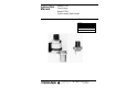
English Français 1. INTRODUCTION 1. INTRODUCTION 1-1. General The flow fittings (Model FF20) and their subassemblies (Model FS20) are used to mount sensor tips in a piping system so that the pH and/or the ORP(Redox) potential of the liquid flowing through it can be measured. The flow fittings are for connection between two pipes of the piping system providing a “flow through” path.
Deutsch Nederlands 1. EINLEITUNG 1. INLEIDING 1-1. Allgemeines Die Durchflußgeber (Modell FF20) und Durchfluß-Einsätze (Modell FS20) dienen zum Einbringen der Sensorspitze in ein Rohrleitungssystem, um den pH-Wert und/oder das Redoxpotential eines fließenden Mediums zu messen. Die Durchflußgeber werden zwischen zwei Rohrstücken eines Leitungssystems eingesetzt.
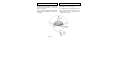
Français English The pressure and temperature ratings of the electrode inside the fitting should be noticed to determine the maximum rating of the measurement point. ne doit pas être inférieur à 15 ° (voir fig. 2-1). L’étendue de pression et de température des électrodes détermine l’étendue de mesure. good bon horizontal horizontale not allowed interdit Fig. 2-1.
Nederlands Deutsch By-pass hinter einem Ventil zur Probenahme installiert werden. Der Winkel zwischen Geber und der Waagerechten darf 15 ° nicht unter schreiten (s. Abb. 2-1). Bei der Auswahl des Meßpunktes sind die Druckund Temperatur-Spezifikationen der Elektroden zu beachten. aanbevolen. De hoek t.o.v. de horizon dient minder dan 15° te zijn (zie fig. 2-1).
English 2-3. Specifications 2-3-1. General specifications MATERIALS - Wetted parts a. body b. O-rings c. liquid earth sensor (not in 1-hole subassembly) : refer to model code : silicone rubber : titanium (plastic designs) SS AISI 316 (SS designs) - Non-wetted parts a. mounting bracket : SS AISI 316 (SS designs) PVC (plastic designs) b. electrode mounting sets : Ryton R4 c. holder for calibration dish : SS AISI 316 d. calibration dish : PP e. retaining nut for electrode holder : SS AISI 304 (excl.
Français 2-3. SPÉCIFICATIONS 2-3-1. Spécifications générales MATERIAUX - pièces en contact avec le fluide a. corps b. joints toriques c. capteur de masse liquide (sauf sous-ensemble à une électrode) : se reporter aux codes modèles : caoutchouc au silicone : titane (modèles plastiques) acier inoxydable AISI 316 (modèles acier inox) - pièces sans contact avec le fluide a. support de montage : acier inoxydable AISI 316 (SS) polychlorure de vinyle (modèles plastique) b. douilles de blocage : Ryton R4 c.
Deutsch 2-3. Spezifikationen 2-3-1. Allgemeine Spezifikationen MATERIAL - Medienberührte Teile a. Körper b. O-Ringe c. Flüssigkeitserde (nicht in Einloch-Gebern) : Siehe Modell- und Zusatzkode. : Silikon : Titan (Kunststoffausführung) Rostfreier Stahl AISI 316 (Edelstahl-Ausführung) - Vom Medium unberührte Teile a. Montagebügel : PVC (Kunststoffausführung), Rostfreier Stahl AISI 316 (Edelstahl-Ausführung) b. Montagesatz für Elektrode : Ryton R4 c.
Nederlands 2-3. Specificaties 2-3-1. Algemene specificaties MATERIALEN - “natte” onderdelen a. behuizing b. O-ringen c. vloeistofaard (niet in 1-gats uitvoering) : zie modelcode : siliconenrubber : titanium (plastic uitvoering) roestvrij staal AISI 316 (SS uitvoering) - niet met vloeistof in aanraking komende delen a. montagebeugel : roestvrij staal AISI 316 (SS uitvoering) polyvinylchloride (plastic uitvoering) b. elektrode-montagesets : Ryton R4 c. houder voor ijkbeker : roestvrij staal AISI 316 d.
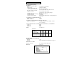
English 2-4. Model and codes 2-4-1. Fittings Model Basic code Option code Description FF20 ......................................................... Flow fitting Material (wetted parts) -P...................................................... Polypropylene (PP) -S...................................................... Stainless steel AISI 316 -F ...................................................... Polyvinylidenefluoride (PVDF) Number of holes 33 ..................................................
Français 2-4. Modèles et codes 2-4-1. Chambre de mesure Modèle Code de base Code option Description FF20 ......................................................... Chambre de mesure Matériaux (en contact avec les fluide) -P...................................................... Polypropylene -S...................................................... Acier inoxydable AISI 316 -F ...................................................... (PVDF) Nombre d’électrodes 33 .........................................
Deutsch 2-4. Modell- und Zusatzkode 2-4-1. Durchflußgeber Modell Grundkode Optionskode Beschreibung FF20 ......................................................... Durchflußgeber Material -P...................................................... Polypropylen (PP) -S...................................................... Rostfreier Stahl AISI 316 (SS) -F ...................................................... Polyvinylidenfluorid (PVDF) Anzahl der Bohrungen 33 ...........................................
Nederlands 2-4. Model en codes 2-4-1. Doorstroom-armaturen Model Basiscode Optiecode Beschrijving FF20 ......................................................... Doorstroom-aramtuur Materiaal (”natte” delen) -P...................................................... Polypropyleen -S...................................................... Roestvrij staal AISI 316 -F ...................................................... Polyvinylideenfluoride Aantal gaten 33 ..............................................
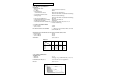
English / Français 2-5. Dimensions / Encombrement 2-5-1. Fittings / Chambres de mesure Deutsch / Nederlands 2-5. Abmessungen / Afmetingen 2-5-1. Geber / Armaturen FF20-.33 FF20-S33 FF20-.
English / Français 2-5-2. Subassemblies / Sous-ensemble Deutsch / Nederlands 2-5-2.
Français English 3. PIPING AND INSTALLATION 3. CONDUITE DE PROCEDE ET INSTALLATION 3-1. General It is important that, whatever method of mounting is used, the point of measurement is truly representative of the entire solution. Avoid an area where the measurement varies significantly or the flow can be interrupted (the sensors must always be immersed in the process liquid). The recommended type of fitting or subassembly will depend on pressure, temperature, kind of liquid, pollution, etc.
Nederlands Deutsch 3. VERROHRUNG UND INSTALLATION 3. LEIDINGEN EN INSTALLATIE 3-1. Allgemeines Der Meßort sollte unabhängig von der Art der Montage so gewählt werden, daß ein repräsentatives Ergebnis erzielt wird. Vermeiden Sie Prozeßbereiche, in denen die Meßwerte stark schwanken oder in denen der Durchfluß unterbrochen werden kann (die Sensorspitze muß immer in das Prozeßmedium eingetaucht sein).
Français English 3-2-2. Mounting in a shunt line By means of a restrictor in the main line a small flow of the process liquid is lead through the flow fitting or subassembly via the shunt line (see fig. 3-2). The pressure in the fitting or subassembly is controlled by means of two valves. 3-2-2.
Nederlands Deutsch 3-2-2. Montage in einer Nebenleitung Durch eine Drossel in der Hauptleitung wird ein Teil des Medium durch eine Probenleitung zum Durchflußgeber bzw. Einsatz geführt (s. Abb. 3-2). Der Druck in der Geberkammer wird durch ein Ventil geregelt. 3-2-2. Montage in een shunt-leiding Met behulp van een begrenzer in de hoofdleiding wordt een klein gedeelte van de vloeistofstroom door armatuur of inzetstuk geleid via de shuntleiding (zie figuur 3-2).
Français English 3-3. Installation 3-3-1. Mounting the fitting Install the fitting at a convenient location for maintenance and calibration. Ensure that there is some place at the top of the fitting (approx. 20 cm) for mounting or replacing the electrodes. Mounting the fitting in a piping system is shown in fig. 3-4. Refer to §2-4 for dimensional drawings. 3-3. Installation 3-3-1. Montage de la chambre de mesure Installer la chambre de mesure dans un endroit où la maintenance sera aisée.
Nederlands Deutsch 3-3. Installation 3-3-1. Installation des Gebers Installieren Sie den Geber in einen repräsentativen Ergebnis für Wartung und Kalibrierung. Bitte beachten Sie, daß ausreichend Platz zum Montieren, bzw. Austauschen der Elektroden über dem Geber vorhanden ist (ca. 20 cm). Abbildung 3-4 zeigt die Montage in einem Rohrleitungsystem. Die Abmessungen zur Befestigung des Gebers entnehmen Sie bitte Abschnitt 2-5. 3-3. Installatie 3-3-1.
Français English 3-3-2. Mounting the subassembly The subassemblies can be cemented or welded directly in a piping system or in a T-piece of it. Install the subassembly at a convenient location for maintenance and calibration. Ensure that there is some place at the top of the fitting (approx. 20 cm) for mounting or replacing the electrodes. Fig. 3-6 shows some mounting examples. Select the mounting position so that the sensors are immersed in the process liquid during measurement. 3-3-2.
Nederlands Deutsch 3-3-2. Installation des Gebereinsatzes Der Gebereinsatz kann direkt in die Prozeßleitung oder in ein T-Stück eingeklebt oder eingeschweißt werden. Installieren Sie den Gebereinsatz in einen repräsentativen Ergebnis für Wartung und Kalibrierung. Bitte beachten Sie, daß ausreichend Platz zum Montieren, bzw. Austauschen der Elektroden über dem Geber vorhanden ist (ca. 20 cm). Abbildung 3-6 zeigt einige Beispiele für diese Montagemöglichkeit.
Français English 3-4-2. Mounting in a 1-hole design Unscrew the electrode mounting set and fix the cable and electrode as shown in fig. 3-8. 3-4-2. Modèle à une électrode Dévisser l’ensemble de montage de l’électrode et fixer le câble et l’électrode comme l’indique la figure 3-8. Fig. 3-8. 3-4-3. Mounting in a 3- and 4-hole design Unscrew the nut from the top end of the fitting or subassembly. Fix the electrodes and cables as shown in fig. 3-9.
Deutsch 3-4-2. Einloch-Geber Schrauben Sie den ElektrodenMontagesatz ab und bereiten Sie Elektrode und Kabel vor wie in Abbildung 3-8 gezeigt. Nederlands 3-4-2. Montage in een 1-gats uitvoering Schroef de montageset voor de elektrode los en monteer kabel en elektrode zoals weergegeven in figuur 3-8. Fig. 3-8. 3-4-3. Drei- und Vierloch-Geber Schrauben Sie die Mutter oben am Geber ab und bereiten Sie Elektroden und Kabel vor wie in Abbildung 3-9 gezeigt.
Français English 4. ACCESSORIES 4. ACCESSOIRES 4-1. General For mounting the non-DIN sized sensors in the fittings and subassemblies Yokogawa added a range of accessories to the program of fittings which can be indespensable tools for optional measuring tools (the specifiactions of the accessories are on separate sheets, see GS12B6W3). See the chapters below for mounting the accessories. 4-1.
Nederlands Deutsch 4. ZUBEHÖR 4. TOEBEHOREN 4-1. Allgemeines Zur Montage von Sensoren mit anderen als DIN-Maßen in einen Geber hat Yokogawa seine Produktpalette erweitert um Zubehör für Gebern, das für optimale Ergebnisse mit diesen Sensoren unerläßlich sein kann. Bitte entnehmen Sie die Spezifikationen den entsprechenden Datenblättern (s. GS12B6W3). Bitte entnehmen Sie unterstehenden Kapiteln zur Installation. 4-1.
English Français 4-3. Mounting kit for sterilisable applications (Model FP20-S14) To assure sterilisable applications and a constant flow of electrolyte this mounting kit can be used for fixing combined electrodes with a large KCl-reservoir (see fig. 4-2). For pressurising the system there is a 1/8” nipple for connecting to each standard pump. The pressure inside the holder may never exceed the specifications of the elec”O”-RINGS trodes. See GS12B6J1 JOINTS for these specifica(82895281) tions. 4-3.
Deutsch Nederlands 4-3. Elektroden-Montagesatz (Modell FP20S14) Um die Möglichkeit zur Sterilisierung und einen konstanten Elektrolytfluß sicherzustellen, kann dieser Montagesatz für Kombielektroden mit großem KCl-Behälter verwendet werden. Abbildung 4-2 zeigt die Montage dieser Elektroden. Zum Anschluß einer Pumpe ist ein 1/8”Nippel vorhanden. Der Druck im Geber darf die ”O”-RINGEN (82895281) Spezifikationen der Elektroden nicht überschreiten.
English Français 4-4. Mounting kit for refillable ref. electro4-4. Kit de montage pour les électrodes redes (order nr. 82850747) chargeables (No 82850747) This mounting kit replaces the standard elecCe kit remplace l’ensemble de montage de l’étrode mounting set so that electrodes of lectrode standard pour fixer les électrodes à Yokogawa with a long glass shaft can be fixed long corps sur une chambre de mesure ou un in the fitting or subassous-ensemble (voir sembly (see fig. 4-3). fig. 4-3).
Deutsch Nederlands 4-4. Montagesatz (Bestellnr.: 82850747) 4-4. Montageset voor navulbare elektroden Dieser Montagesatz ersetzt den Standard(bestelnr. 82850747) Montagesatz bei der Installation von nachfüllDeze montageset vervangt de standaard montabaren Elektroden mit langem Glasschaft.
Français English 4-5. Cleaning systems 4-5-1. General The standardised design of the fittings and subassemblies makes it possible to mount cleaning systems directly. The 4-hole types are especially designed for these applications. Three different types of cleaning systems are available (see fig. 4-4): - mechanical cleaning (electrically or mechanically driven) - chemical cleaning - ultra sonic cleaning. Detailed specifications of the cleaning systems are on separate sheets (see GS12B6V1) 4-5.
Nederlands Deutsch 4-5. Reinigungssysteme 4-5.1. Allgemeines Die standardisierte Konstruktion der Geber erlaubt den direkten Einsatz von Reinigungssystemen. Die 4-Lochtypen sind speziell für diese Applikation konzipiert. YOKOGAWA bietet drei verschiedene Reinigungssysteme an (s. Abb. 4-4): - Mechanische Reinigung (Bürste, mit elektrischem oder pneumatischem Antrieb) - Chemische Reinigung - Ultraschall-Reinigung Bitte entnehmen Sie die Spezifikationen den entsprechenden Datenblättern (s. GS12B6V1). 4-5.
Français English 4-5-3. Mechanical cleaning The brush of this cleaning system periodically strikes along the sensitive glass membrane of the electrode, so that this part is wiped frequently preventing sediment formation on it. Electrically or pneumatically versions are available. 4-5-3. Nettoyage mécanique La brosse du système passe sur la membrane de verre de l’électrode toutes les 30 secondes. L’entraînement est électrique ou pneumatique, selon les versions.
Nederlands Deutsch 4-5-3. Mechanische Reinigung (Bürste) Bei der mechanischen Bürstenreinigung fährt eine Bürste periodisch über die Glasmembran der Elektrode. Für diese Reinigungseinheit kann zwischen elektrischem und pneumatischem Antrieb gewählt werden. 4-5-3. Mechanische reiniging De borstel van dit reinigingssysteem veegt periodiek over het glazen membraan van de elektrode zodat dit deel frequent wordt schoongeveegd en aanslag wordt voorkomen.
Français English Pneumatically driven brush cleaning (Model FC20-VP) Fig. 4-6 shows the mounting. Entraînement pneumatique pour système de nettoyage à brosse (Modèle FC20-VP). La figure 4-6 indique le montage. CONTROL UNIT COMMANDE PNEUMATIQUE TUBING TUBE (K1520NA) PISTON ”O”-RINGS JOINTS (11 x 3) PROTECTION HOSE GAIN DE PROTECTION K1520NC BRUSH HOLDER SUPPORT DE BROSSE Fig. 4-6. PARTS AND ACCESSORIES ORDER NR.
Nederlands Deutsch Pneumatischer Antrieb (Modell FC20-VP) Bürstenreinigung Die Abbildung 4-6 zeigt die Installation. Pneumatisch aangedreven borstelreiniger (Model FC20-VP). In fig. 4-6 is de montage weergegeven. REGLER REGELEENHEID SCHLAUCH SLANG (K1520NA) KOLBEN PISTON ”O” RINGE ”O”-RINGEN (11 x 3) SCHUTZSCHLAUCH BESCHERMSLANG BURSTENHALTER BORSTELHOUDER Fig. 4-6. TEILE UND ZUBEHÖR ONDERDELEN EN TOEBEHOREN BESTELLNR K1520NA K1520NB K1520NC K1520NG K1520NH K1520NJ BESTELNR.
English Français 4-4-4. Chemical cleaning (Model FC20-ECN2) The chemical cleaning system is based on periodically spraying of a cleanser onto the glass membrane of the electrode. This cleaning system is effective in processes where deposits can be removed by a suitable solvent. Good cleaning effects can be obtained using hot water or a chemically cleaning reagent. The built-in (no return) nozzle in the spray unit prevents penetration of the process liquid in the cleaning system.
Deutsch Nederlands 4-4-4. Chemische Reinigung (Modell FC20ECN2) Bei der chemischen Reinigung wird in regelmäßigen Abständen eine Reinigungslösung auf die Glasmembran der Elektrode gesprüht. Welcher Reiniger in welchen Zeitabständen einzusetzen ist, hängt vom Prozeß ab. Eine gute Reinigungs-Wirkung wird erzielt, indem periodisch heißes Wasser oder eine Reinigungschemikalie auf die Glasmembran gesprüht wird.
Français English 4-4-5. Ultra sonic cleaning (Model FC20-BU) With the ultra sonic cleaning system the liquid around the glass membrane of the electrode is vibrated. The cleaning effect is highly dependent on the vibration energy and the velocity passing the electrodes. On a generator this energy can be adjusted. 4-4-5. Nettoyage à ultrasons (modèle FC20-BU) Ce système génère une vibration du liquide autour de la membrane de verre, cela évite ou élimine les dépôts sur celle-ci.
Nederlands Deutsch 4-5-5. Ultraschall-Reinigung (Modell FC20-BU) Bei der Ultraschall-Reinigung werden Ultraschall-Schwingungen um die Glasmembran der Elektrode herum erzeugt, um vorhandene Ablagerungen zu entfernen und neue Verschmutzungen zu verhindern. Der erzielte Reinigungseffekt ist bei dieser Methode sehr stark von der Fließgeschwindigkeit des Mediums anhängig. Die Intensität der Schwingungen kann über das Steuergerät eingestellt werden. 4-4-5.
Français English 4-5. Salt bridge (Model SB20-VC) This reference electrode/salt bridge combination allows pH and ORP(Redox) measurement with the normal electrodes in those cases when: a. excessive contamination of the ceramic flow diaphragm is expected - the flow of the reference liquid through the diaphragm is increased by pressurising the container. Consequently, the contamination rate will decrease. b.
Nederlands Deutsch 4-5. Salzbrücke (Modell SB20-VC) Diese Kombination von Referenzelektrode und Salzbrücke erlaubt die pH- und RedoxMessung mit normalen Elektroden, wenn folgende Situationen vorliegen: a. Zu erwartende übermäßige Verschmutzung des Diaphragmas. Der Durchfluß des Referenzelektrolyten wird erhöht, indem der Behälter unter Druck gehalten wird. Daher nimmt die Neigung zum Zusetzen ab. b. Im Prozeß kann eine Verunreinigung mit KCl nicht toleriert werden.
English Français 5. MAINTENANCE 5. MAINTENANCE 5-1 General Before the electrodes can be serviced, the electrode holder should be physically separated from the process. The fittings can be changed from the measuring position in the maintenance position by following the reversed procedures described in §4. 5-1. Généralités Avant de procéder à la maintenance, le support des électrodes doit être sorti du procédé.
Deutsch Nederlands 5. WARTUNG UND INSPEKTION 5. ONDERHOUD 5-1. Allgemeines Trennen Sie die Elektrodenhalterung physikalisch vom gegenwärtigen Prozeß, bevor Sie die Wartungsarbeiten ausführen. Der Geber kann in wenigen Schritten vom Prozeß getrennt und in die Wartungsposition gebracht werden, Führen Sie die umgekehrte Anweisungen unter Kapitel 4 aus. 5-1. Algemeen Alvorens service aan de elektroden kan worden uitgevoerd, dient de houder voor deze elektroden fysiek te worden gescheiden van het proces.
English Français The PTFE diaphragm of the combined electrode can sometimes be regenerated by putting it in hot (60 to 80 °C) 1 molar Potassium chloride (KCl) solution and letting it cool to room temperature. After cleaning the probe is re-inserted into the process by following the reverse procedure (see §3-5).
Deutsch Nederlands Das PTFE-Diaphragma einer Elektrode kann in einigen Fällen regeneriert werden, indem es in heißer (60 bis 80 °C), 1 molare KaliumchloridSäure (KCl) eingetaucht und dann auf Raumtemperatur abgekühlt wird. Het PTFE-diafragma van de referentie-elektrode kan soms worden gereinigd door het in een warme oplossing (60 tot 80 °C) van 1 molair chloorkalium (KCl) te zetten en af te laten koelen tot kamertemperatuur.
English 5-4. Replacing the O-rings The exploded view (see §6) shows the position of the sealing O-rings. The O-rings used in the wetted part are made of silicone rubber, which has superior resistance to corrosion suitable for use with most process liquids. Usually no periodical inspection is necessary. To prevent trouble, replace the O-ring seal periodically, e.g. every year. Français 5-4.
Deutsch 5-4. Überprüfung der Dichtungsringe Die in den medienberührten Bereichen des Eintauchgebers verwendeten O-Ringe sind aus Silikon-Kautschuk gefertigt, das eine sehr gute Beständigkeit aufweist und zudem problemlos mit den meisten Medien verwendet werden kann. Unter normalen Betriebsbedingungen ist keine Inspektion der O-Ringe erforderlich. Um einen störungsfreien Betrieb sicherzustellen, sollten die Dichtungen jedoch regelmäßig (einmal im Jahr) ausgetauscht werden. Nederlands 5-4.
English / Français 6. EXPLODED VIEW 6. VUE EXPLOSEE Deutsch / Nederlands 6. EXPLOSIONSZEICHNUNG 6. DOORSNEETEKENINGEN FF20- . 33 FF20- .
FS20- . 12 FS20- . 33 FS20- .
English Français 7. SPARE PARTS LIST TYPE NR. 82895375 82895376 82895279 82895276 82895275 82895283 FP20-R12 FP20-S12 82895002 82895001 WU20-PC2 WU20-PC5 WU20-PC10 WU20-LT2 WU20-LT5 WU20-LT10 82895202 82895208 82895203 82895258 DESCRIPTION Calibration dish for 3-hole fitting (50 x) Calibration dish for 4-hole fitting (50 x) O-ring (11 x 3)(0.43” x 0.
Deutsch Nederlands 7.
UNITED KINGDOM Yokogawa United Kingdom Ltd. Stuart Road, Manor Park, RUNCORN Cheshire WA7 1TR Tel. +44-1-928 597100 Fax +44-1-928 597101 YOKOGAWA EUROPEAN HEADQUARTERS Yokogawa Europe B.V. Vanadiumweg 11, 3812 PX AMERSFOORT The Netherlands Tel. +31-33-4641 611 Fax +31-33-4641 610 E-mail: info@yokogawa.nl www.yokogawa-europe.com THE NETHERLANDS Yokogawa Nederland B.V. Hoofdveste 11 3992 DH HOUTEN Tel. +31-30-635 77 77 Fax +31-30-635 77 70 AUSTRIA Yokogawa Austria Ges.m.b.H.