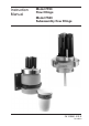
Instruction Manual Model FF20 Flow fittings Model FS20 Subassembly flow fittings IM 12B6K1-01E-E 7th edition
1. INTRODUCTION..........................................................................................................1 1-1. General................................................................................................................1 1-2. Features...............................................................................................................1 2. UNPACKING AND CHECKING...................................................................................1 2-1.
1 1. INTRODUCTION 1-1. General The flow fittings (Model FF20) and their subassemblies (Model FS20) are used to mount sensor tips in a piping system so that the pH and/or the ORP (Redox) potential of the liquid flowing through it can be measured. The flow fittings are for connection between two pipes of the piping system providing a “flow through” path. From a practical plant aspect (for easy maintenance and calibration) the mounting place is in a by-pass behind a sample valve.
2 2-3. Specificaitons 2-3-1. General specifications MATERIALS - Wetted parts a. body b. O-rings c. liquid earth sensor (not in 1-hole subassembly) : refer to model code : silicon rubber : titanium (plastic designs) SS AISI 316 (SS designs) - Non-wetted parts a. mounting bracket :S S AISI 316 (SS designs) PVC (plastic designs) b. electrode mounting sets : Ryton R4 c. holder for calibration dish : SS AISI 316 d. calibration dish : PP e.
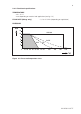
3 2-3-2. Funcitonal specifications TEMPERATURE - min -10 °C - max depending on material and application (see fig. 2-2) FLOW RATE (fittings only) : 0,1 to 10 1/min (depending on applicaiton) PRESSURE bar 12 AISI 316 10 8 6 4 PVC PP PVDF 2 0 10 20 30 40 50 60 70 80 100 120 140 160 Figure 2-2.
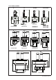
4 2-4. Model and codes 2-4-1.
5 2-4-2.
6 2-5. DIMENSIONS 2-5-1. Flow Fittings 52 [2.05"] PP/PVDF 1/2" NPT IN F F20-P22 FF20-F22 3x5 ½" NPT inlet = 48 [1.89"] = 76 [2.99] 175 [6.89"] Ø 90 (3.5 4") 17.5 [0.69"] 255 [10.04"] 55 (2.16") Ø7 1 (2. 80") ½"NPT Outlet 70.3 [2.77"] 60 (2.36") 71 [2.80"] 67 [2.64"] OU T 276 (10.82") 1/2" NPT Ø 8 (0,31") 36,5 (1.43") SS 9 [5 0.3 5"] FF20-S22 SS PP/PVDF ½" NPT inlet = 48 [1.89"] = 76 [2.99"] Ø 90 (3.5 4") 175 [6.89"] FF20-P33 FF20-F33 FF20-S33 PP/PVDF SS 150 (5.90") 230 (9.
2-5-2. Subassamblies PP/PVDF 189(7,44") 2-11.5 NPT ANSI B.21.1 2-11,5NPT ANSI B.20.1 81.5(3.21") 112 (4.41") 92(3.62") 190(7.48") 82(3.23") Ø56 (2.20") 112(4.41") 124(4.88") 112 (4.41") 60 (2.36") 112 (4.41") PP/PVC/PVDF 200(7.87") SS 169 (6.65") SS Ø 63 (2.48") FS20-P22-TP FS20-F22-TP FS20-P22-WE FS20-V22-WE FS20-F22-WE SS SS PP/PVDF PP/PVC/PVDF 2-11,5 NPT ANSI B.20.1 Ø 63 (2.48") FS20-P32-WE FS20-V32-WE FS20-F32-WE FS20-P32-TP FS20-F32-TP FS20-S32-TP PVC 26 (1.
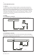
8 3. PIPING AND INSTALLATION 3-1. General It is important that, whatever method of mounting is used, the point of measurment is truly representative of the entrie solution. Avoid an area where the measurement varies significantly or the flow can be interrupted (the sensors must always be immersed in the process liquid). The recommended type of fitting or subassembly will depend on pressure, 12B6K1-40 MOUNTING A temperature, kind of liquid, pollution, etc.
MOUNTING IN A SAMPLE LINE +CONNECT. FOR BUFFER... 9 3-2-3. Mounting in a sample line with extra connection for buffer liquid/cleanser The sample line has an extra input for cleaning or calibration (see fig. 3-3). 12B MOUNTING PROCESS PIPING buffer liquid cleaner 12B6K1-44 MOUNTING THE FITTING DRAIN Figure 3-3 3-3. Installation 3-3-1. Mounting the fitting Install the fitting at a convenient location for maintenance and calibration. Ensure that there is some place at the top of the fitting (approx.
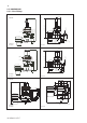
10 3-3-2. Mounting the subassembly The subassembly can be cemented or welded directly in a piping system or in a T-piece of it. Install the subassembly at a convenient location for maintenance and calibration. Ensure that there is some place at the top of the fitting (approx. 20 cm) for mounting or replacing electrodes. Fig. 3-6 shows some mounting examples. Select the mounting position so that the sensors are immersed in the process liquid during measurement. (Model WU20) should be used (see fig. 3-7).
11 3-4-2. Mounting in a 1-hole design Unscrew the electrode mounting set and fix the cable and electrode as shown in fig. 3-8. 3-4-3. Mounting in a 3- and 4-hole design Unscrew the nut from the top end of the fitting or subassembly. Fix the electrodes and cables as shown in fig. 3-9. Note: In the holes for placing the electrodes are blanking plugs (stoppers). These plugs can be placed in unused holes after pushing the two O-rings over the bottom end.
12 RECOMMENDED ELECTRODES1) TYPE DESCRIPTION SR20-AC32 Reference electrode SC29-PTC542) Combined redox/ref. electrode 1 2 ) For specifications of the electrodes see GS 12B6J1 ) Atmospheric conditions only PARTS AND ACCESSORIES ORDER NR. DESCRIPTION K1500HC Set rubber ring (10x) K1500GE Set O-rings (5x) for BELLOMATIC electrode K1500GF 250 ml KCI-solution (1 m.) K1520VA 250 ml KCI-solution (3,3 m.) K1500GG 250 ml KCI-solution (1 m.) thickend K1520VN 250 ml KCI-solution, (3,3 m.) thickend 4-3.
13 4-4. M ounting kit for refillable ref. electrodes This mounting kit replaces the standard electrode mouting set so that elctrodes of Yokogawa with a long glass shaft can be fixed in the fitting or subassembly (see fig. 4-3). This mounting kit may be used as process pressure up to 3 bar. Higher pressure ratings require the standard mounting set for electrodes with DIN dimensions or, alternately a salt bridge (see §4-5).
14 4-5-2. Selection criteria cleaning system mechanical brush chemical acid base acoustical K1547PP (spare ultra tubing, EPDM) emulsifier sonic Applications: oils fats x resins (wood, pulp) x emulsions of latex x fibers (paper, textile) x crystalline precipations (carbonates) x xx amorpheus precipations x xx x x x x 4-5-3.
15 Pneumatically driven brush cleaning (Model FC20-VP) PARTS AND ACCESSORIES ORDER NR. DESCRIPTION K1520NA Tubing (ø4 mm) K1520NG Brush holder K1520NB Brush K1520NG Protection hose K1520NH Piston K1520NJ Control unit CONTROL UNIT PROTECTION HOSE K1520NC TUBING K1520NA PISTON O-RING (11x 3) BRUSH HOLDER Figure 4-6 Example FC20-VP 4-5-4. Chemical cleaning HCN. The chemical cleaning system is effective in processes where deposits can be removed by a suitable solvent.
16 Specifications Materials Nozzle O-rings Mounting set Tubing Process cond. : : : : : Hastelloy EPDM rubber Stainless steel 1/4” (OD Ø) Nylon tubing Max. 1 MPa (10 bar) at 100 ºC Mounting K1547PA K1547PA K1547PB K1547PJ : : : : / HCN2, 2-hole flow-, insertion fitting (PH20) /HCN3, 3-hole flow-, insertion-, immersion fitting /HCN4, 4-hole flow-, insertion-, immersion fitting /HCNF, back-end mounting on FU20/PH20 4-5.
17 Connection Weight Mounting Temperature/ pressure ratio : nylon : approx. 300 g. : wall mounting (support with hole for screw M5) : max. 200 kPa (2 bar) at 100°C Notes: 1. The dimensions of the flow tube equal to those of standard electrodes 2. The standard reference electrodes can be mounted in the container 3. To observe the electrolyte level, the container is made of PVC. For mounting instructions see fig. 4-9 PARTS AND ACCESSORIES ORDER NR.
18 ATTENTION Avoid using non-polar solvents like tri-chloro ethylene, toluene or hexane. Even cleaning with ethanol or acetone is not recommended. These solvents will break up the gel-layer on the glass bulb and afterwards needs to remain soaked in water for at least 12 hours before functioning normal. The PTFE diaphragm of the combined electrode can sometimes be regenerated by putting it in hot (60 to 80 °C) 1 molar Potassium chloride (KCl) solution and letting it cool to room temperature.
ASSEMBLED FLOW FF20-.33 19 6. EXPLODED VIEW 12B6K1-32 ASSEMBLED FLOW FF20-.43 FF20- .33 FF20- P22 FF20- F22 FF20-.
20 FS20-.12 12B6K1-35 SUBASSY FLOW FS20-.33 12B6K1-36 SUBASSY FLOW FS20-.43 FS20- .32 FS20-S22 FS20-P22 FS20-F22 FS20-V22 FS20-.
21 SPARE PARTS Accesoires Part no.
22 Spare parts FF20 Part no. Description K1500BV O-rings EPDM 11x3 (6 Pcs.) K1500BW Flow tube for SB20-VC K1500BY Option /R for F*20.. (82850747) K1500BZ O-rings Viton 11x3 (6Pcs)51250 K1500DU Liquid earth cable 25m K1500DW Set of 12 cable nuts for WU20 K1500DX 5 m tubing for SB20 K1500DZ Nut SS, FF/S20-3* + ISC40FF/S K1500EK O-rings viton 6.07x1.
23 K1521AM K1521AN K1521AP K1521AQ K1547PA K1547PB K1547PF K1547PG K1547PH K1547PP Flange adapter /FP1 Flange adapter /FS2 Flange adapter /FF2 Flange adapter /FP2 Hast. cleaning unit HCN2/3 Hast.
24 IM 12B6K1-01E-E
25 IM 12B6K1-01E-E
YOKOGAWA ELECTRIC CORPORATION World Headquarters 9-32, Nakacho 2-chome, Musashino-shi Tokyo 180-8750 Japan www.yokogawa.com YOKOGAWA ELECTRIC ASIA Pte. LTD. 5 Bedok South Road Singapore 469270 Singapore www.yokogawa.com/sg YOKOGAWA CORPORATION OF AMERICA 2 Dart Road Newnan GA 30265 USA www.yokogawa.com/us YOKOGAWA CHINA CO. LTD. 3F Tower D Cartelo Crocodile Building No.568 West Tianshan Road Changing District Shanghai, China www.yokogawa.