IM 01R01A30-01EN-B January, 2014 V 1.
Safety Information Failure to follow all instructions could result in injury. Read, understand and follow all safety warnings and instructions provided with this product. Also, meet or exceed your employer’s safety practices. In no event shall Yokogawa be liable for any indirect, special, incidental, consequential or punitive damages or for any lost profits arising out of or relating to any services provided by Yokogawa or its affiliates.
ATEX DOCUMENTATION applies only to European Union countries.
S RO GR M
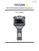
YHC5150X FieldMate Handheld Communicator USER’S MANUAL TABLE OF CONTENTS Subject Page YHC5150X Series Communicator Overview ............................................................................................ 1 Touchscreen Display Overview .......................................................................................................... 2 Display Layout ...............................................................................................................................
Updating Software ................................................................................................................................... 34 Hazardous Area Use ................................................................................................................................ 34 Intrinsically Safe Operation............................................................................................................... 34 Returning for Repair ............................................
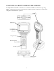
1.0 YHC5150X Series HART® COMMUNICATOR OVERVIEW The YHC5150X Series HART® Communicator is a full function HART® Communicator supporting HART® communication Universal, Common Practice and Device Specific commands for commissioning, configuration and maintenance operations.
1.1 TOUCHSCREEN DISPLAY OVERVIEW The communicator has a 4.3-inch widescreen backlit TFT color touchscreen display with 480 x 272 WQVGA pixel resolution. The entire viewable area of the screen is an active touch surface. The touchscreen responds to and is optimized for finger presses (even through gloves). NO stylus is necessary. Never touch the screen with sharp objects – simply use your finger. Display Layouts There are two styles of displays presented on the communicator, system menu displays (Section 3.
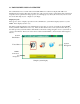
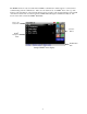
The HART® menus are only accessible when a HART® communication enabled device is connected and communicating with the communicator. There are four distinct areas on a HART® menu. The top of the menu provides information on the currently attached device as well as various status indicators. The middle of the menu is divided into two functional areas, HART® Menu Navigation and Function Buttons. The bottom of the menu contains the HART® Menu Path.
1.2 Keyboard Layout Alpha Entry Backspace Upper/Lower case Toggle OK or Accept Cancel Navigation Ring Enter or Select Advance or Switch (to next functional area on screen) Information or Help Numeric Entry (and Menu Accelerators) Power (Section 2.1) Backlight (Section 2.2) The communicator provides a high functionality keyboard, combined with touch screen data keys, to simplify data entry and navigation. Most tasks can be completed by just using the dedicated keyboard.
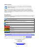
2.0 GENERAL OPERATION 2.1 Power Button The Power Button has two functions: Power On – Whenever the communicator is in an “Off” state, pressing the power key turns the communicator on. This is a complete system start. The communicator will execute a complete power op sequence. Information regarding the time and date is briefly displayed to allow the user to verify the communicator’s readiness .
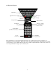
The battery pack contains an advanced battery fuel gauge that actively monitors the battery capacity and therefore does not require any “battery training” throughout the life of the battery pack. 2.6 PC Communication / Recharging Cradle The Recharging Cradle, included with each unit, automatically recharges the li-ion battery pack when the communicator is properly inserted into the energized cradle. To fully charge a depleted battery pack takes about four and one half hours.
The Recharging Cradle is not rated for intrinsic safety and should only be used in a non-hazardous area. See the “Hazardous Area Use” section of this manual and the Intrinsic Safety Control Drawing in the Appendix of this manual for more information. 2.7 Battery Pack Installation & Removal The battery pack is held into the communicator by two standard 6-32 screws with hexagonal sockets that require a 7/64” hex key wrench.
2.7 Memory Card The communicator is shipped standard with a µSD memory system card. The system card is used for storage of required software, software updates, HART® DD files and device configuration files. It is not intended for use unrelated to the operation of the communicator. When the µSD memory system card is in the YHC5150X, the user has no access to the card except with the Yokogawa provided PC software.
2.9 External Connections Loop Communication Jacks / Lead Set – All models are equipped with a standard size banana jack on 0.75” center. The lead set supplied with the communicator has a standard banana plug on one end and minigrabbers on the other for convenient connections. For Intrinsically Safe model YHC5150X, verify the instruments in the loop are installed in accordance with intrinsically safe field wiring practices before making connection from the field device to the Unit’s loop communication jack.
2.10 Keyboard Functionality The keyboard is logically arranged into four areas based on the frequency of use. The alpha and fixed function keys will be used less frequently than the navigation and numeric keys. Alpha & Decision Navigation & Information Numeric Fixed Function The alpha keys contain all 26 characters of the ISO basic Latin alphabet. They are arranged in the same order as a standard QWERTY keyboard.
Decision keys (hard key) are active when decision buttons appear on the screen. Their function is duplicated by the decision buttons (touch screen button). Decision keys are also used for some auxiliary functions. See sections 3.2 (Create shortcuts) for detail. KEY BUTTON DECISION = CANCEL/ESC = ACCEPT Navigation keys are used to move focus around the display and to select the item that is in-focus.
2.11 Touch Keyboard Functionality The YHC5150X Series and HART® communication support the ISO Latin-1 (ISO 8859-1) character set for most text data entry. This character set contains 191 characters. Of these characters 65 are available on the communicator main keyboard. The remaining characters, and duplication of the ISO basic Latin alphabet (lower + upper case) are available from the touch screen. Whenever a text edit window appears the touch keyboard is visible too.
Keyset #2 Keyset #3 (lower case) Keyset #3 (upper case) Keyset #4 (upper case) Keyset #4 (lower case) Keyset #5 (upper case) Keyset #5 (lower case) 13
3.0 Navigating the Communicator THREE WAYS TO NAVIGATE Focus Pane - The focus pane is used in every system menu to indicate what icon will be selected when the Select Key is pressed. Focus is changed by use of the Arrow Keys. Select Key and the Arrow Keys are part of the keyboard navigation ring. Navigation Number – The navigation number at the upper right of each icon indicates what icon will be selected when the corresponding character on the keyboard is pressed.
Battery Status – Is a quick reference to the current condition of the battery. More detailed information is available under system information. Current Time – The current time offset from the initial user setting. System Navigation The function of the icons in this area will differ on every system display and will be covered in the specific display sections following.
Multi-drop - If the HART® connection status bar indicates there are multiple devices found select the bar to bring up a list of those devices: Select desired device to connect by using the Arrow Keys or touching the appropriate line. Finalize your selection by pressing the Accept icon, or the Accept key () below the alpha keyboard. Cancel this operation by pressing the Cancel Icon, or the Cancel/Esc key () located below the alpha keyboard.
System Menu - Main System Setup Provides access to the system setup menus for changing communicator parameters. HART®Setup Provides access to the HART® setup menus for changing HART® specific parameters. System Information Provides access to information regarding model number, software versions, battery life etc.
System Menu - System Setup Date and Time Setup Power Management Language Touch Screen Calibration Access to set the current date and time for timestamps on files and system indicators. Access to settings for adjusting power consumption (backlight timers etc.) User selects the preferred language of system menus and HART® menus (if supported). Allows user to calibrate the touch screen.
Language Selecting this icon allows the user to change the language that will be used for System menus, system messages, and HART® menus (if supported by the manufacturer DD). When the icon is selected a list of supported languages is displayed: Select desired language by using the Arrow Keys or touching the appropriate line. Finalize your selection by pressing the Accept icon, or the Accept key () below the alpha keyboard.
System Menu - Date And Time Setup Date Adjust the system day, month, and year Time Adjust the system minutes and hour 12 or 24 Hour Mode Choose standard (12 hour) or military (24 hour) time for display.
System Menu - Power Management Display Auto Dim Timer Set time before reducing the backlight to the minimum setting (10%) during periods of inactivity. Auto Standby Timer Set time before switching system to standby mode during periods of inactivity.
System Menu - HART® Setup The HART® Setup Menu provides access to the following: HART® Polling Address Range Selection ® Setup HART Tag For Display Allows user to select a range of addresses to poll, or to select a tag or long tag to use in polling for a HART® enabled device. User can select which tag to display on HART® status line. Choices are tag or long tag. If long tag does not exist on the connected device, short tag will always be displayed.
System Menu - System Information The System Information menu provides communicator reference data.
3.2 HART® Menu HART® Menus can be accessed once a HART® device has been properly connected and the HART® communication is established between that device and the communicator. There are three navigable panes on the HART® Menus: The Navigation Menu, the Function Buttons, and the Menu Path. Focus is shifted between these three panes by pressing the Advance/Switch key.
HART® Menu - HART® Navigation Menu The information in this area is controlled by the HART® DD that is activated to communicate with the HART® device. This in turn is determined by the manufacturer of the device and the HART® Communication Foundation. The last column at the right of the pane indicates item status. The small green arrows indicate that the menu item value has not been committed to the device. This particular status only applies to parameters. Parameter has been changed by the user.
HART® Menu - Function Buttons System Settings Create Shortcuts Configuration Options Hot Key Menu Commit Changes Display Status User Shortcut There are two ways to navigate the function buttons. Use the navigation ring on the keyboard, or the touch screen. Create Shortcuts – The user would select this icon if he wished to create a User Shortcut to the current HART® Navigation Menu.
1. It is invalid to create a shortcut on the home menu (often labeled “Online”). 2. If a primary menu has submenus (designated by 0 –MORE- in the tenth line) the shortcut created will be to the primary menu regardless of the submenu currently being displayed. System Settings returns the user to the System Setup Main menu. The HART® connection is maintained. The user just selects the green HART® Connection status bar to return to the HART® Menus when they have finished on the System Menus.
HART® Menu - HART® Menu Path The HART® Menu Path displays current menu name and all the menu names along the menu path traversed to reach the current menu. Intermediate menu Online menu (home) Current menu The HART® Menu Path provides direct access to any of the menus along the menu path. Select the desired menu, using touch screen or arrow keys, from those displayed on the Path Bar, and it will become the active menu. 4.0 HART® Communication with the YHC5150X Series 4.
4.2 HART® Connections HART® connections are made using two standard banana jacks (3/4” center) located at the top end of the communicator. Refer to the following diagram. Polarity is not a concern for HART® connections so both jack collars are black. Yokogawa supplies a HART® lead kit (1W-A900529-00014) complete with minigrabber connections and a 250 Ω load resistor with each unit.
When connecting the communicator to a loop with a resistive load greater than 250 Ωs, the HART® jacks may be connected across the load, the loop + and -, or to the HART® device communication terminals. Refer to the following diagram for connecting across the loop + and -. . Do not connect the communicator across the loop supply. This does not provide the proper resistance and no HART® communication will be possible. 4.
If the bar indicates devices have been found you can select which device to connect by selecting the bar. This brings up a list box from which to pick your device. Once you choose a device and press Accept, the box will collapse and the communicator will initiate connection. Once the device is connected the bar will turn green. If the poll address range is a single address, and a device is found at that address, the communicator will immediately initiate connection, and additional polling is terminated.
4.5 Using Generic HART® Communication The Generic HART® Communication mode starts automatically when HART® communication is initiated with a device for which no Device Specific DD (device object file) is stored in the handhelds flash memory. When this occurs, line two of the display will indicate “Generic” and the device tag number. In general, the Generic HART® mode operates similarly to its device specific DD counterpart (see HART® Communication section of this manual for more details).
The user now has the option of making further modifications to the parameters on the HART® menu, or committing them to the device. 4.7 Communication Troubleshooting If a HART® device is connected to the unit but “No Devices Found” notification is received, or the device is not in the table of found devices: 1) Make sure all connections are correct and secure. Check for shorts, open circuits and multiple grounds. 2) Determine if the loop resistance is greater than 250Ω and less than 1100Ωs.
5.0 Updating Software To update software a PC and a USB cable are required. Details are shown in the website below: http://www.yokogawa.com/us/products/field-instruments/ia-smart-communicators/yhc5150x.htm 6.0 HAZARDOUS AREA USE Hazardous area use is permitted only when user complies with laws and regulations of the country or region where the communicator is used. Intrinsically Safe Operation The YHC5150X HART® Communicator includes certification for Intrinsically Safe operation.
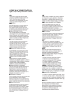
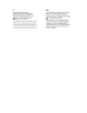
Note the following WARNINGS and REQUIREMENTS for YHC5150X models: • Substitution of components may impair Intrinsic Safety • To prevent ignition of flammable or explosive atmospheres; Disconnect power before servicing Do not use battery charger in a hazardous atmosphere. DO NOT attempt to open the battery pack and replace the batteries. Serious injury or death may result from explosions.
7.0 RETURNING FOR REPAIR In the event that a YHC5150X Series requires service and must be returned for repair, please contact Yokogawa at the numbers listed below. DO NOT send any unit in for repair without first contacting Yokogawa for a Return Material Authorization (RMA) number. If this number has not been obtained and clearly marked on the package being shipped back, the unit will be returned at the shipper’s expense.
APPENDIX PRODUCT SPECIFICATIONS BASE UNIT: 11.9" L, 5.6” W (at display), 2.50” W (at handle), 1.9” D. PC/ABS alloy plastic case with shock absorbing bumpers, rated IP51, 2.1 lbs including battery. Passes one meter drop test onto concrete DISPLAY: 4.3-inch widescreen backlit TFT color touch screen display with 480 x 272 WQVGA pixel resolution. POWER: Li-ion battery pack, 3.6 volts nominal. 1.5A recharging cradle. 100-240Vac, 50/60Hz input.
SAFETY NOTICES Do not subject the batteries to intense heat. This could cause overheating, fire, rupture or explosion. If an electric shock is felt when touching the charger or YHC5150X docked in the charger, unplug charger immediately from outlet. Remove the YHC5150X from the charger immediately after you determine it is safe. If there is any deformation, cracks or other damage to the charger base, power cord, or power adapter, unplug the charger and discontinue use.
INTRINSIC SAFETY CONTROL DRAWING
EC Declaration of Conformity This is to declare, in accordance with Directive 94/9/EC, that the following product(s) are designed and manufactured in accordance with Annex II of Directive 94/9/EC. The manufacturer attests on their own responsibility that the apparatus has been constructed in accordance with the principles of good engineering in safety matters, and that any routine verification and test required by Clause 27 of EN 60079-0:2006 has been successfully completed.