User’s Manual M Series Digital Limit Alarms Communication Functions IM 77J04J11-01E IM 77J04J11-01E 1st Edition
Blank Page
i Introduction This user's manual describes the communication functions of the M Series digital limit alarms (hereinafter simply referred to as M Series) and contains information on how to create communication programs. Read the manual carefully to understand the communication functions of the M Series. The M Series have the following communication protocols.
ii Documentation Conventions ■ Symbols The following symbols are used in this manual. ● Symbols Used in the Main Text CAUTION Draws attention to information that is essential for understanding the operation and/or features of the product. TIP Gives additional information to complement the present topic. See Also Gives reference locations for further information on the topic.
iii Notices ■ Regarding This User's Manual (1) This manual should be passed on to the end user. Keep the manual in a safe place. (2) Read this manual carefully to gain a thorough understanding of how to operate this product before you start using it. (3) This manual is intended to describe the functions of this product. Yokogawa Electric Corporation (hereinafter simply referred to as Yokogawa) does not guarantee that these functions are suited to the particular purpose of the user.
iv ■ Force Majeure (1) Yokogawa does not make any warranties regarding the product except those mentioned in the WARRANTY that is provided separately. (2) Yokogawa assumes no liability to any party for any loss or damage, direct or indirect, caused by the use or any unpredictable defect of the product. (3) Be sure to use the spare parts approved by Yokogawa when replacing parts or consumables. (4) Modification of the product is strictly prohibited.
Toc-1 M Series Digital Limit Alarms Communication Functions IM 77J04J11-01E 1st Edition CONTENTS Introduction........................................................................................................... i Documentation Conventions ...............................................................................ii Notices .................................................................................................................iii 1. 2. Setup .........................
Toc-2 3.3 4. 5. Communication with Higher-level Devices ................................................. 3-20 3.3.1 Example of Communication Program Created Using Visual Basic .. 3-21 3.3.2 Communication with UT Link Module .............................................. 3-25 3.3.3 Communication with Touch Panel ................................................... 3-26 Ladder Communication .......................................................................... 4-1 4.
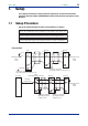
1. 1-1 <1. Setup > Setup This chapter describes the setup procedure required to use the communication functions (PC link, Ladder and MODBUS) and the communication parameters of the M Series. 1.1 Setup Procedure Set up the communication functions on the M Series as follows: Set up the communication function parameters of the M Series. (See section 1.2.) Connect a higher-level device and a M Series. (See the connection diagram below.
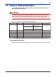
1.2 1-2 <1. Setup > Notes on Setting Parameters This section describes the setting parameters for using the communication functions and their setting ranges. CAUTION The details of M Series communication functions need to be the same as those of the communication functions of the higher-level device to be connected. Check the communication parameters of the higher-level device first, then set up those of the M Series.
<1. Setup > 1-3 ● Address number (ADR) Set the address number of the M Series itself. An address number of 1 to 99 can be assigned in any order. Note that the number of M Series that can be connected to a single communication port is limited to 31.
Blank Page
2. <2. Communication Specifications > 2-1 Communication Specifications The RS-485 communication interface has the PC link communication, Ladder communication and MODBUS communication protocols.
Blank Page
<3. PC Link Communication > 3. PC Link Communication 3.1 Overview 3-1 The use of PC link communication enables the M Series to communicate with a device such as a PC, graphic panel and FA-M3 UT link module easily. In this communication, you can use such device to read/write data from/into D registers or I relays, both of which are internal registers of the M Series.
3.1.1 3-2 <3. PC Link Communication > Configuration of Command Commands sent from a higher-level device to the M Series consist of the following elements. Number of Bytes 1 2 2 Element STX Address number (ADR) CPU number 01 (1) (2) (3) 1 3 Time to wait Command for response 0 (4) (5) Variable length 2 1 1 Data corresponding to command Checksum ETX CR (6) (7) (8) (9) (1) STX (Start of Text) This control code indicates the start of a command.
3.1.2 3-3 <3. PC Link Communication > Configuration of Response Responses from the M Series with respect to a command sent from the higher-level device consist of the following elements, which differ depending on the condition of communication; normal or failure. 1) Normal Communication If communication succeeded, a character string "OK" is returned with the data corresponding to a command.
3.1.3 <3. PC Link Communication > 3-4 Response Error Codes See Also 3.1.2, "Configuration of Response", for the structure of response in the event of error. The error codes (EC1) and detailed error codes (EC2) of responses are as follows. Table 3-1 Error Code List of Error Codes EC1 Meaning Cause(s) 02 Command error • No command exists. • Command not executable 03 Register specification error • No register number exists.
3.1.4 <3. PC Link Communication > 3-5 Specifying Broadcast Broadcast addressing allows the corresponding multiple M Series to receive the command. (1) To use this function, specify BM for the address number in a command. (2) Broadcast addressing works independently of the address number. (3) Broadcast addressing is only applicable to write commands. (4) No response is returned if broadcast addressing is used. Higher-level device (master) Broadcast data.
3-6 <3. PC Link Communication > 3.2 Commands 3.2.1 List of Commands The following shows lists of commands available in PC link communication. Their details are explained in the description of each command.
3-7 <3. PC Link Communication > BRD Reads I relays on a bit-by-bit basis ● Function Reads the ON/OFF statuses of a sequence of contiguous I relays by the specified number of bits, starting at a specified I relay number. • The number of bits to be read at a time is 1 to 256. • For the format of response in the event of failure, see subsection 3.1.2. • The command shown below includes the checksum function.
3-8 <3. PC Link Communication > BWR Writes data into I relays on a bit-by-bit basis ● Function Writes ON/OFF data into a sequence of contiguous I relays by the specified number of bits, starting at a specified I relay number. • The number of bits to be written into at a time is 1 to 256. • For the format of response in the event of failure, see subsection 3.1.2. • The command shown below includes the checksum function.
3-9 <3. PC Link Communication > BRR Reads I relays on a bit-by-bit basis in random order ● Function Reads the ON/OFF statuses of the individuaI I relays specified in random order by the specified number of bits. • The number of bits to be read at a time is 1 to 32. • For the format of response in the event of failure, see subsection 3.1.2. • The command shown below includes the checksum function.
3-10 <3. PC Link Communication > BRW Writes data into I relays on a bit-by-bit basis in random order ● Function Writes ON/OFF data into the individual I relays specified in random order by the specified number of bits. • The number of bits to be written into at a time is 1 to 32. • For the format of response in the event of failure, see subsection 3.1.2. • The command shown below includes the checksum function.
3-11 <3. PC Link Communication > BRS Specifies I relays to be monitored on a bit-by-bit basis ● Function Specifies the I-relay numbers to be monitored on a bit-by-bit basis. Note that this command simply specifies I relays. Actual monitoring is performed by the BRM command after the I relay numbers are specified by this command.
3-12 <3. PC Link Communication > BRM Monitors I relays on a bit-by-bit basis ● Function Reads the ON/OFF statuses of the I relays that have been specified in advance by the BRS command. • Before executing this command, the BRS command must always be executed to specify which I relays are to be monitored. If no relay has been specified, error code 06 is returned. • For the format of response in the event of failure, see subsection 3.1.2.
3-13 <3. PC Link Communication > WRD Reads D registers and I relays on a word-by-word basis ● Function Reads a sequence of contiguous register data on a word-by-word basis by the specified number of words, starting at a specified register number. • The number of words to be read at a time is 1 to 64. • For the format of response in the event of failure, see subsection 3.1.2. • The command shown below includes the checksum function.
3-14 <3. PC Link Communication > WWR Writes data into D registers and I relays on a word-by-word basis ● Function Writes data into a sequence of contiguous registers on a word-by-word basis by the specified number of words, starting at a specified register number . • The number of words to be written into at a time is 1 to 64. • For the format of response in the event of failure, see subsection 3.1.2. • The command shown below includes the checksum function.
3-15 <3. PC Link Communication > WRR Reads D registers and I relays on a word-by-word basis in random order ● Function Reads the statuses of the individul registers on a word-by-word basis specified in random order by the specified number of words. • The number of words to be read at a time is 1 to 32. • For the format of response in the event of failure, see subsection 3.1.2. • The command shown below includes the checksum function.
3-16 <3. PC Link Communication > WRW Writes data into D registers and I relays on a word-by-word basis in random order ● Function Writes register data specified for each register into the registers specified in random order by the specified number of words. • The number of words to be written into at a time is 1 to 32. • For the format of response in the event of failure, see subsection 3.1.2. • The command shown below includes the checksum function.
3-17 <3. PC Link Communication > WRS Specifies D registers and I relays to be monitored on a word-by-word basis ● Function Specifies the register numbers to be monitored on a word-by-word basis. Note that this command simply specifies the registers. Actual monitoring is performed by the WRM command after the register numbers are specified by this command.
3-18 <3. PC Link Communication > WRM Monitors D registers and I relays on a word-by-word basis ● Function Reads the register data that have been specified in advance by the WRS command. • Before executing this command, the WRS command must always be executed to specify which registers are to be monitored. If no register has been specified, error code 06 is generated. • For the format of response in the event of failure, see subsection 3.1.2.
3-19 <3. PC Link Communication > INF Reads the model, range code number, number of alarms and revision ● Function Returns the model, range code number, number of alarms and revision of the M Series. • For the format of response in the event of failure, see subsection 3.1.2.
3.3 <3. PC Link Communication > 3-20 Communication with Higher-level Devices Higher-level devices are those capable of using the PC link communication protocol. As an example of a communication program, the Basic program created using Microsoft Visual Basic is given in subsection 3.3.1. Further, communications with an FA-M3 UT link module or touch panel can be achieved without creating a complex program. Examples of communication with them are given in subsections 3.3.2 and 3.3.3.
3.3.1 <3. PC Link Communication > 3-21 Example of Communication Program Created Using Visual Basic This subsection shows a sample program created using Microsoft Visual Basic 6.0. Operation verification environment: PC/AT compatible machine + Windows NT 4.0 (SP4), Windows 95 PC/AT is a product of IBM Corporation. Visual Basic is a registered trademark of Microsoft Corporation. See Also MSDN and commercially available documentation for information on Visual Basic programming.
<3. PC Link Communication > 3-22 Label1.Caption = "[stx]" + strSend + "[etx][cr]" Label2.Caption = "" MSComm1.PortOpen = True Timer1.Enabled = True Command1.Enabled = False fSend = True 'Open port 'Start timer for detecting timeout 'Disable the Command button temporarily 'Set sending flag 'Send MSComm1.
<3. PC Link Communication > 3-23 'Initialize label control that displays character strings sent and received Label1.Caption = "" Label2.Caption = "" End Sub -------------------------------------------------------------------------------'This processing starts each time 1 byte is received Private Sub MSComm1_OnComm() Dim strBuf0 As String Select Case MSComm1.CommEvent Case comEvReceive strBuf0 = MSComm1.
<3. PC Link Communication > strReceive = "Time Out!" fSend = False 3-24 'Receiving is regarded as being ended End Sub IM 77J04J11-01E 1st Edition : 2006.08.
3.3.2 <3. PC Link Communication > 3-25 Communication with UT Link Module Communication with FA-M3 is achieved by simply connecting the M Series to a UT link module using the PC link communication protocol. Set the communication conditions of the M Series identical to those of the UT link module.
3.3.3 3-26 <3. PC Link Communication > Communication with Touch Panel Communication with a touch panel is achieved using the PC link communication protocol. Set the communication conditions of the M Series identical to those of the touch panel. Graphic panel A maximum of 1200 m; up to 31 slave stations For more information, refer to the user's manual of the touch panel to be connected.
<4. Ladder Communication > 4. Ladder Communication 4.1 Overview 4-1 The use of Ladder communication enables the M Series to communicate with a sequencer (PLC). By specifying the register numbers of D registers of the M Series as parameters in the ladder program, you can read/write data from/into the registers using BCD codes (0 to 9).
4.2 4-2 <4. Ladder Communication > Commands/Responses at the PLC The PLC sends commands and receives responses to these commands. The commands and responses that can be used are as follows. 4.2.1 Configuration of Command/Response Commands sent from the PLC to the M Series and responses from the M Series with respect to a command sent from the PLC consist of the following elements.
4.2.2 4-3 <4. Ladder Communication > Reading Parameters Shown below are the configurations of commands and responses when parameters in the M Series are read by the PLC. (The maximum number of data items to be read is 64.
4.2.3 4-4 <4. Ladder Communication > Writing Parameters Shown below are the configurations of commands and responses when the parameters are written into the M Series from the PLC.
4.2.4 4-5 <4. Ladder Communication > Response Error Codes Data that the master station (PLC) will receive in the event of an error and the description of errors are given in the table below. 0101/0103/0000/0001/CR/LF Read/write data 0, 0, R/W, and +/Parameter number Address number and CPU number Note: Slashes (/) in the following send and receive data examples are used for explanatory purposes only, and are not part of the actual data string.
Blank Page
<5. MODBUS Communication > 5. MODBUS Communication 5.1 Overview 5-1 The use of MODBUS communication enables the M Series to communicate with a PC. In this communication, you can use a PC to read/write data from/into D registers, which are internal registers of the M Series. PC A maximum of 1200 m; up to 31 slave stations Figure 5-1 Example of Connection for MODBUS Communication Hereafter, PCs are generically called "higher-level devices.
5.1.1 5-2 <5. MODBUS Communication > Configuration of Message Messages sent from a higher-level device to the M Series consist of the following elements. Element Start of Message Mark Address Number (ADR) Function Code Data Error Check End of Message Mark Number of bytes in RTU mode None 1 1 Number of bytes in ASCII mode 1 2 2 2n 2 None 4n 2 2 (1) (2) (3) (4) (5) (6) (1) Start of Message Mark This mark indicates the start of a message.
5.1.2 <5. MODBUS Communication > 5-3 Specifying D Registers When you use a commercially available SCADA or the like or a user-created communication program, you must be careful when specifying D register numbers contained in messages because in both cases, you cannot use the original D register numbers as they are. 1) When using a commercially available SCADA or the like, specify D register numbers by changing them into reference numbers.
<5. MODBUS Communication > 5.2 Function Codes 5.2.1 List of Function Codes 5-4 Function codes are command words used by the higher-level device to obtain the D register data of the M Series. Table 5-2 Code Number List of Function Codes Function Description 03 Reads data from multiple registers. Capable of reading data from a maximum of 64 successive registers. 06 Writes data into a register. Capable of writing data into one register. 08 Performs loop back test.
03 5-5 <5. MODBUS Communication > Reads data from multiple D registers ● Function Reads the contents of a sequence of contiguous D registers by the specified number of D registers, starting at a specified D register number. • The maximum number of D registers to be read at a time is 64. • For the format of response in the event of failure, see subsection 5.2.2.
<5. MODBUS Communication > 5-6 ● Example: Reading the statuses of alarm-1 and alarm-2 setpoints of the M Series with address number 01. The following message reads two successive D registers starting at alarm-1 setpoint (D0101) of address number 01 in the ASCII mode.
06 5-7 <5. MODBUS Communication > Writes data into a D register ● Function Writes data into a specified D register. • The maximum number of D registers to be written into at a time is 1. • For the format of response in the event of failure, see subsection 5.2.2. • Broadcast addressing is possible by setting 00 in the address number.
<5. MODBUS Communication > 5-8 ● Example: Setting 70.00 into the alarms-1 setpoint of the M Series with address number 01. The following message writes 70.00 into the alarms-1 setpoint (D0101) of address number 01 in the ASCII mode. [Message] : 010600641B5822[CR][LF] Start of message mark "01": address number 01, "06": function code 06, "0064": D-register number 0101, "1B58": data 70.00, and "22": error check Note: The numbers in quotation marks are hexadecimal.
08 5-9 <5. MODBUS Communication > Performs loop back test ● Function This function code is used to check the connection for communication. • For the format of response in the event of failure, see subsection 5.2.2. • The element marked with * is "00" (fixed). • Any value can be selected for send data.
16 5-10 <5. MODBUS Communication > Writes data into multiple D registers ● Function Writes data into a sequence of contiguous D registers by the specified number of D registers, starting at a specified D register number. • The maximum number of D registers to be written into at a time is 32. • For the format of response in the event of failure, see subsection 5.2.2. • Broadcast addressing is possible by setting 00 in the address number.
<5. MODBUS Communication > 5-11 ● Example: Setting 200, 10 and 3 into the alarms-1 setpoint, alarm-2 setpoint and alarm-3 setpoint of the M Series with address number 02, respectively. The following message writes 200, 10 and 3 in this order in the ASCII mode, starting at the alarm-1 setpoint (D0101) of address number 02 .
5.2.2 5-12 <5. MODBUS Communication > Response Error Codes ● Message Format in the Event of Error If there are any inconsistencies other than communication errors in a message, the M Series does nothing, but returns the following message.
5.2.3 <5. MODBUS Communication > 5-13 Specifying Broadcast Broadcast addressing allows the corresponding multiple M Series to receive the command. (1) To use this function, specify 00 in the address number. (2) Broadcast addressing works independently of the address number. (3) Broadcast addressing is only applicable to write commands. (4) No response is returned if broadcast addressing is used. Higher-level device (master) Broadcast data.
Blank Page
<6. Functions and Usage of D Registers > 6. Functions and Usage of D Registers 6.1 Overview of D Registers 6-1 This section describes the functions and usage of D registers. The D registers store the input and output values, statuses and others that are handled by the M Series.
6.3 <6. Functions and Usage of D Registers > 6-2 D Register Map Table D-Register Data Area D-Reg No. D0001 D0002 D0003 D0004 D0005 to D0100 D0101 D0102 D0103 D0104 D0105 D0106 D0107 D0108 D0109 D0110 D0111 D0112 D0113 D0114 D0115 D0116 D0117 to D0200 D0201 D0202 D0203 D0204 D0205 D0206 to D0209 D0210 D0211 D0212 D0213 D0214 D0215 D0216 to D0300 D0301 D0302 D0303 D0304 D0305 D0306 D0307 to D0308 D0309 D0310 D0311 D0312 D0313 to D0400 D0401 to D0450 Ref No. 40001 40002 40003 40004 H No.
6.3.1 <6. Functions and Usage of D Registers > 6-3 Contents of D Registers ● D0001: Bit configuration of status The D0001 register represents errors and parameter data by a combination of bits in the register. In the table below, if any of the events shown occurs, the corresponding bit is set to "1." The bit remains set to "0" if the event has not occurred yet. Note that blank fields indicate bits not used, which are in "0.
<6. Functions and Usage of D Registers > 6-4 ● D0003: INPUT (Input value: display value) ● D0004: IN UNIT (Input unit) D0004 value Unit Model H'0000 No unit H'0003 degC MVTK, MVRK H'0004 K MVTK, MVRK MVHK IM 77J04J11-01E 1st Edition : 2006.08.
7. <7. Functions and Usage of I Relays > 7-1 Functions and Usage of I Relays This chapter describes the functions and usage of the I relays. The I relays store information on errors, alarm statuses and others of the M Series. The higher-level device can read data from I relays or write data into I relays using PC link communication. IM 77J04J11-01E 1st Edition : 2006.08.
7.1 <7. Functions and Usage of I Relays > 7-2 Status The following table shows how the I relays are classified. I-Relay No. 1 to 16 Type of Status ON/OFF Description Error information (same contents as those of D0001) 17 to 32 Alarm status (same contents as those of D0002) 33 to 64 User area (that is used in some devices such as graphic panels) CAUTION • The I relays numbered 1 to 32 store ON/OFF statuses. Generally, this area can be accessed to read the ON/OFF statuses.
App.-1 Appendix Table of ASCII Codes (Alphanumeric Codes) In order to implement PC link communication, create a transmission/receiving program by referring to the Table of ASCII Codes below.
Blank Page
i Revision Information ● Title : M Series Digital Limit Alarms Communication Functions ● Manual No. : IM 77J04J11-01E Aug. 2006/1st Edition Newly published Written by Yokogawa Electric Corporation Published by Yokogawa Electric Corporation 2-9-32 Nakacho, Musashino-shi, Tokyo 180-8750, JAPAN IM 77J04J11-01E 1st Edition : 2006.08.
Blank Page