
User Manual

3
All Rights Reserved. Copyright © 1999, Yokogawa M&C Corporation
IM 77J01H07-01E
3rd Edition Mar.31,1997-00
IMPORTANT
● If this instrument is used in a manner not sepecified in
this manual, the protection provided by this instrument
may be impaired.
● If the product is operated by a power supply exceeding
the specifications, the product may become extremely
hot and, as a result, damaged. To prevent this, ensure
the following before turning on the power.
(a) The voltage of the supplied power and the input
signal level meet the specifications of the product.
(b) External wires are connected to the correct termi-
nals (refer to Chapter 5).
● Do not operate the product in the presence of flammable
or explosive gases or vapors. To do so is highly danger-
ous.
● The product is sensitive to static electricity; exercise
care in operating it. Before you operate the product,
touch a nearby metal part to discharge static electricity.
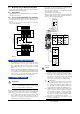
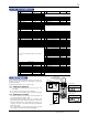
7. DESCRIPTION OF FRONT PANEL
AND CONNECTION OF HANDY
TERMINAL
7.1 Front Panel
The communications connector in the front panel is used for set-
ting up parameters through the Handy Terminal. The alarm-1 and
alarm-2 LEDs light up if an alarm occurs (those LEDs are pro-
vided only when the output-2 is specified for alarm output).
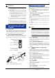
7.2 Connecting the Handy Terminal
Connect the modular jack-to-connector adapter to the connection
cable (with 5-pin connector) of the Handy Terminal and then con-
nect this adapter to the communications connector of the distribu-
tor.
ALM1
ALM2
Alarm-1 LED
(lights up if an alarm occurs)
Communications connector
(for connecting the
Handy Terminal)
Alarm-2 LED
(lights up if an alarm occurs)
* The LEDs are provided only when output-2
is specified for alarm output.
Fig. 7.1 Front Panel
E9786WH
Modular jack-to-connector
adapter (optional)
VJ Series
Communications
connector
JHT200
Handy Terminal (optional)
F9182EE
Connection cable (optional)
Fig. 7.2 Connecting the Handy Terminal
8. SETTING PARAMETERS
Set the parameters using the Handy Terminal. Refer to the list of pa-
rameters in this manual and the Instruction Manual for Handy Termi-
nal (IM JF81-02E).
8.1 Settings Related to Inputs and Outputs
8.1.1 Input Type
Set by selecting input type from among VOLTS (DC voltage) and
CURRENT (DC current) in D16: INP TYPE.
8.1.2 Input Hard Range
Set by selecting the input hard range from among AUTO, HIGH,
MIDDLE, and LOW in D17: SELECT RANGE. Generally, select
AUTO.
● AUTO: Sets the input hard range automatically with respect to
the input range to be set.
● HIGH: For a span of 5 V or more in an input range of -10 to
+10 V
● MIDDLE: For a span of 2.5 V or more in an input range of -5
to +5 V
● LOW: For a span of 0.5 V or more in an input range of -1 to
+1 V
NOTE
The conditions for the input hard range (HIGH, MIDDLE,
and LOW) are specified for operations within the range of
accuracy rating. The input range may be set to a range not
meeting these conditions, but take note of accuracy limita-
tions. Similar accuracy limitations exist even when AUTO
is selected. For more information on accuracy limitations,
see the general specifications of VJH7 (GS 77J1H07-01E).
8.1.3 Input Range
Set the 0% value of input range to D22: INPUT1 L_RANGE and
the 100% value of input range to D23: INPUT1 H_RANGE within
the numerically specified range.
8.1.4 Direction of Output Action
Analog output signals can be reversed. To reverse the signal from
output-1, set D38: OUT1 DR to REVERSE. For output-2, set D39
OUT2 DR to REVERSE. To return the output-1 signal to normal,
set D38: OUT1 DR to DIRECT. For output-2, set D39: OUT2 DR
to DIRECT.
8.2 Settings Related to Communication
Function
Set the following parameters when output-2 is specified for com-
munication function. For more information on the communication
function, see the Instruction Manual for VJ Series Communication
Function (IM 77J1J11-01E).
8.2.1 Communication Protocol
Set the communication protocol by selecting from among PC-
LINK, PC-LINK WITH SUM, MODBUS ASCII, MODBUS
RTU, and LADDER in F01: PROTOCOL.
8.2.2 Communication Address
Set the address number of the isolator numerically in a range of 1
to 99 in F02: ADDRESS.
8.2.3 Baud Rate
Set the baud rate by selecting from among 1200, 2400, 4800, and
9600 bps in F03: BAUD RATE.
8.2.4 Parity
Select and set NONE, EVEN, or ODD in F04: PARITY.
8.2.5 Data Length
Select and set 7 bits or 8 bits in F05: DATA LEN.