
Manual

6
All Rights Reserved. Copyright © 1999, Yokogawa M&C Corporation IM 77J1X07-01E
10.LIST OF PARAMETERS
No. Item Display Remarks No. Item Display Remarks
01 Model MODEL
02 Tag No. TAG NO
03 Self-check result SELF CHK
Display items
A Display1 DISPLAY1 B Display2 DISPLAY2
A01 Input value INPUT1 B01 Input value INPUT1
A03 Output value 1 OUTPUT1 B03 Output value 1 OUTPUT1
A04 Output value 2 OUTPUT2 B04 Output value 2 OUTPUT2
A09 Temporary memory 1 T1 B09 Temporary memory 1 T1
A10 Temporary memory 2 T2 B10 Temporary memory 2 T2
A11 Temporary memory 3 T3 B11 Temporary memory 3 T3
A12 Temporary memory 4 T4 B12 Temporary memory 4 T4
A14 Digital output DO B14 Digital output DO
A15 Load factor LOAD B15 Load factor LOAD
A54 Status STATUS *1 B55 Status MENU REV
A55 MENU REV MENU REV B60 Self-check result SELF CHK
A60 Self-check SELF CHK *1 The Status is displayed for service personnel to see history records.
Setting items
D Setting (I/O) SET(I/O) F Setting (communication) SET (COM)
D01 Tag no. 1 TAG NO.1 F01 Communication protocol PROTOCOL
D02 Tag no. 2 TAG NO.2 F02 Address ADDRESS
D03 Comment 1 COMMENT1 F03 Baud rate BAUD RATE
D04 Comment 2 COMMENT2 F04 Parity PARITY
D16 Input type INP TYPE F05 Data length DATA LEN
D17 Selection of input hard range SELECT RANGE F06 Stop bit STOP BIT
D18 Input resistor IN RESIST
There are items not displayed depending on what output-2 is specified.
D22 Input low range INPUT1 L_RNG
D23 Input high range INPUT1 H_RNG
D32 Selection of program PRGM SELECT
D35 Computing period CYCLE TIME
D38 Direction of output-1 action OUT1 DR
D39 Direction of output-2 action OUT2 DR
D60 Self-check result SELF CHK
Programming items Fixed constant setting items
G Program of computing unit PROGRAM H Fixed constant of computing unit CONST
G01 Program PROGRAM H01 Fixed constant CONST
↑↑ ↑ ↑ ↑ ↑
↓↓ ↓ ↓ ↓ ↓
G40 Program PROGRAM H59 Fixed constant CONST
G60 Self-check result SELF CHK H60 Self-check result SELF CHK
Adjusting items Test items
P Adjustment ADJUST1 Q Test TEST
P02 Zero adjustment of input-1 ZERO ADJ1 Q02 Forced output 1 OUT1 TEST
P03 Span adjustment of input-1 SPAN ADJ1 Q03 Forced output 2 OUT2 TEST
P12 0% adjustment of output-1 OUT1 0% Q06 Forced output (relay 1) RLY1 TEST
P13 100% adjustment of output-1 OUT1 100% Q07 Forced output (relay 2) RLY2 TEST
P14 0% adjustment of output-2 OUT2 0% Q60 Self-check result SELF CHK
P15 100% adjustment of output-2 OUT2 100%
P17 Adjustment of external input resistance RESISTOR ADJ
P60 Self-check result SELF CHK
1011
3 2
1
4
56
789
11
10
8
L+
N–
GND
Power supply
9
7
Analog output
Output-1 signal
Voltmeter
R
R: For current output using 250 Ω
precision resistor
Voltage and
current
generator
+
–
5
2
Analog output
Output-2 signal
Voltmeter
R
R: For current output using 250 Ω
precision resistor
+
–
Input signal
3
1
+
–
Analog input
R
R: 100 Ω
Externally connected
for current input
Shunt resistor
(Externally connected
for current input)
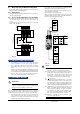
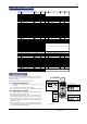
Fig. 11.1
11.MAINTENANCE
The product starts running immediately when the power is turned on;
however, it needs 10 to 15 minutes of warm-up before it meets the
specified performance.
For cleaning the instrument, use a soft and dry cloth.
11.1 Calibration Apparatus
● A voltage and current generator (Yokogawa 7651 or the
equivalent)
● A voltmeter (Yokogawa 7562 or the equivalent)
●
A precision resistor of 250 ⍀ ± 0.01%, 1 W (for current output)
11.2 Calibration Procedure
Connect the instruments as shown in Fig. 10.1. First adjust the out-
put-1 signal and then the output-2 signal.
Produce input signals equivalent to 0, 25, 50, 75, and 100% of the
input span from the voltage and current generator to the isolator.
Then, check that the isolator’s output signal shows voltages corre-
sponding to 0, 25, 50, 75, and 100% of the input span within the
rated accuracy range.
If the output signal is out of the rated accuracy range, adjust the
output signal level using PC (VJ77 PC-based Parameters Setting
Tool) or the Handy Terminal (JHT200).