User's Manual PK200 CURRENT-TO-PNEUMATIC CONVERTER [Style:S2] IM 21B03D01-01E IM 21B03D01-01E 12th Edition
CONTENTS CONTENTS INTRODUCTION .............................................................................................. iii 1. HANDLING PRECAUTIONS ......................................................................... 1-1 1.1 1.2 1.3 1.4 1.5 Checking the Model Suffix Code and Specifications .......................... 1-1 Transportation Precautions ................................................................. 1-1 Storage Precautions .......................................................
CONTENTS 6. MAINTENANCE ............................................................................................. 6-1 6.1 6.2 Overview ............................................................................................. 6-1 Periodic Inspection .............................................................................. 6-1 6.2.1 Cleaning the Restrictor ................................................................. 6-1 6.3 Parts Replacement ...............................................
INTRODUCTION INTRODUCTION Thank you for purchasing the Current-to-Pneumatic Converter. • Yokogawa will not be liable for malfunctions or damage resulting from any modification made to this instrument by the customer. The Current-to-Pneumatic Converter is correctly calibrated at the factory before shipment. To ensure correct and efficient use of the instrument, please read this manual thoroughly and fully understand how to operate the instrument before operating it.
INTRODUCTION WARRANTY • The warranty shall cover the period noted on the quotation presented to the purchaser at the time of purchase. Problems occurred during the warranty period shall basically be repaired free of charge. • In case of problems, the customer should contact the Yokogawa representative from which the instrument was purchased, or the nearest Yokogawa office.
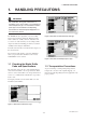
1. HANDLING PRECAUTIONS 1. HANDLING PRECAUTIONS IMPORTANT For installation, wiring and maintenance in hazadous areas, please follow 1.5 Installation of Intrinsically Safe Type, 1.6 Installation of Flameproof Type and “Installation and Operating Precautions for TIIS Flameproof Equipment” at the end of this manual The PK200 current-to-pneumatic converter is fully factory inspected before shipment.
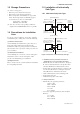
1. HANDLING PRECAUTIONS 1.3 Storage Precautions (1) Select a storage place : • Which is protected from rain and water. • Which is free from vibration and impact. • Whose temperature and humidity are as specified below. Room temperature and humidity (approx. 25°C and 65%) are more recommendable. Temperature: -10 to 60°C Humidity: Less than 80% (2) Store the converter in the packing condition of shipment from YOKOGAWA whenever possible. 1.5 Installation of Intrinsically Safe Type 1.5.
1. HANDLING PRECAUTIONS 3. Installation • Control equipment connected to barrier must not use or generate more than 250 Vrms or Vdc. • The safety barrier must be CSA certified. • Associated apparatus manufacturer’s installation drawing must be followed when installing this apparatus. • The maximum power delivered from the barrier must not exceed 0.9 W. • Note a warning label worded “SUBSTITUTION OF COMPONENTS MAY IMPAIR INTRINSIC SAFETY” and “INSTALL IN ACCORDANCE WITH DOC. NO. ICS006-A12 P.1 AND 2”. 1.5.
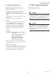
1. HANDLING PRECAUTIONS 1.6.2 FM Explosionproof Type 1.7 EMC Conformity Standard Following items are described in the instruction documents of this instrument to ensure certified explosionproof properties. EN61326-1 Class A, Table 2 (For use in industrial locations) 1. PK200 Current to Pneumatic Converter is applicable for use in hazardous areas; * Explosionproof for Class I, Division 1, Groups B, C and D. * Dust ignitionproof for Class I/II, Division 1, Groups E, F and G.
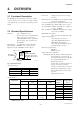
2. OVERVIEW 2. OVERVIEW 2.1 Functional Description I/O Action: The PK200 current-to-pneumatic converter is a signal converter that receives an electronic controller or DCS control signal and converts it into a pneumatic pressure signal. 2.2 Standard Specifications Materials: Case: Aluminum die-cast Paint: Polyurethane resin-baked finish Paint color: Deep-sea moss-green (Munsell 0.6GY3.1/2.
2. OVERVIEW 2.4 Options TIIS Intrinsically Safe (/JS3): Intrinsically Safe Ex ia IIC T4 Certificate: TC18266 Explosionproof Construction: TIIS Explosionproof (/JF3): Flameproof Exd II B+H2 T6X FM Explosionproof (/FF1): Explosionproof for Class I, Division 1, Groups B, C and D. Dust ignitionproof for Class II/III, Division 1, Groups E, F and G. Temperature Class: T6. Outdoor hazardous locations, NEMA 4X.
2. OVERVIEW • Option Code/L: Lightning Protector Installed in the terminal box to protect internal circuitry from high voltage surges such as those caused by lightning induced. • Option Code/AM: AUTO/MANUAL Switch Mounted on front of housing, in manual mode, output signal is varied by adjusting the external supply pressure regulator. • Option Code/SS: Stainless Steal Screw and Bracket Screw and bracket, both are made of stainless steal.
2. OVERVIEW 2.6 Part Names Terminal box cover Converter cover Supply gauge Zero adjustment Output gauge F0203.EPS Figure 2.3 Part Names (1) Span adjustment Electrical connection Terminal board Case Zero adjustment Amplifier Ground terminal F0204.EPS Figure 2.
3. INSTALLATION 3. INSTALLATION 3.1 Overview 3.2.2 Wall Mounting When installing the PK200 converter, see section 1.4 “Precautions for Installation Area.” For the ambient environmental conditions of an installation place, see section 2.2 “Standard Specifications.” When the instrument is installed on the wall, use the two M8 screws provided. 3.2 Installation PK200 can be installed on a pipe using a mounting bracket provided or directly installed on the wall.
4. WIRING AND PIPING 4. WIRING AND PIPING 4.1 Piping 4.1.3 Output Piping 4.1.1 Supply Air Connect output air piping to the output connection OUT of the converter. For easy operation and maintenance, supply air must be clean and dry. Generally, use copper tubes of 6mm O.D. and 4mm I.D., air piping, and coupling to install output air piping. After installing the piping, check for leakage.
4. WIRING AND PIPING 4.2.2 Wiring CAUTION (1) Install wiring away from noise sources such as a large capacity transformer, motor, or power supply. Tighten the gland approximately one turn after the point where you can no longer shift the cable up and down by hand. Take great care in this step, since proper tightening is very important. (2) Remove terminal box cover and wiring connection dustproof plugs, then connect wiring.
4. WIRING AND PIPING Figure 4.1 General-Use and Flameproof Type Wiring Figure 4.2 Flameproof Metal Conduit Wiring Figure 4.
4. WIRING AND PIPING 4.2.3 Grounding (1) Provide grounding with a ground resistance of 100Ω. ⫹ Current signal ⫺ (2) Grounding terminals are provided inside and outside of the terminal box. Use either terminal. G Ground (3) Use 600V PVC insulated wire for grounding wiring. F0404.EPS Figure 4.4 Wiring 4.
5. OPERATION 5. OPERATION 5.1 Auto/Manual (A/M) Transfer Mechanism Please refer to following instruction for the model with A/M selector switch (optional code: /AM). For the model without A/M selector switch, please go to section 5.2. Use of A/M transfer mechanism requires that a supply pressure adjusting reducing valve be installed. (1) Set the A/M selector switch provided at the front (on the supply air pressure gauge side) of the converter to “M.” (Turn the switch clockwise.) 5.
5. OPERATION Adjust the zero adjustment so that an output signal of 20kPa is obtained when a 4mA input signal is applied. Table 5.3 Recommended Supply Air Pressure Table 5.2 Output Signals Output Signal Code Output Signal 1 20 to 100kPa 2 40 to 200kPa 3 0.2 to 1.0kgf/cm2 4 0.4 to 2.0kgf/cm2 5 0.2 to 1.0bar 6 0.4 to 2.
5. OPERATION For the model with reverse action (/RA), please turn span adjustment counterclockwise to increase output air pressure. To decrease output pressure, please turn span adjustment clockwise. (9) After completing adjustments, change the input signal to 0%, 25%, 50%, 75%, and 100% and confirm if the specified output is reached at the relevant input. Confirm the accuracy with reference to the input and output signal reference values given in Table 5.5 “Input and Output Signals.
5. OPERATION 5.4 Range Adjustment Perform the following to change to an output signal other than those specified in Table 5.4 “Output Signals.” Zero point adjustable range is ±10% of span and the span adjustable range is from 100 to 125%. An output signal can be flexibly regulated within these ranges using the zero and span adjustments. Table 5.
6. MAINTENANCE 6. MAINTENANCE 6.1 Overview 6.2.1 Cleaning the Restrictor The PK200 converter components are structured as units to allow easy maintenance. Remove the restrictor shown in Figure 6.1 using a screw driver and thread a wire with 0.3mm dia. into the restrictor for cleaning. This chapter describes cleaning of each component and part replacement to be conducted for PK200 maintenance.
6. MAINTENANCE 6.3.3 Replacing the Amplifier Assembly An amplifier for replacement comes with a tube and four set screws. Removing the Amplifier (1) Turn off the power and set the air supply pressure to zero. Screen filter (2) Turn the amplifier cover counterclockwise to remove it. F0604.EPS Figure 6.4 Removing the Screen Filter (IN Side) (3) Adjust the zero adjustment control to the position indicated in Figure 6.6. 6.3.2 Replacing the Controller Relay (1) Set the air supply pressure to zero.
6. MAINTENANCE (7) Pull out the amplifier directly, taking care not to bend the zero adjustment control. NOTE 1.Do not apply undue pressure to the pressure sensor. 2.Do not bend the zero adjustment volume knob to prevent it from contacting the zero adjustment set screw. (8) Remove the silicon tube left in the case. Mounting the Amplifier (1) Insert the accessory silicon tube into the body cap firmly. (4) Fasten the four set screws for fixing the amplifier (see Figure 6.7).
6. MAINTENANCE (3) Where a built-in arrester is provided (suffix code: /A), the voltage for the insulation resistance test must be 100V DC or lower, and the voltage for the withstand voltage test must be 100V AC or lower. Failure to heed these guidelines may cause faulty operation. Follow the steps below to perform the test, the wiring of the communication line must be removed before initiating testing. Insulation resistance test procedure 1.
7. TROUBLESHOOTING 7. TROUBLESHOOTING 7.1 Overview An increase in the input signal causes the flapper at the end of the torque motor moving piece to move in the nozzle closing direction. When the nozzle is closed, back pressure increases, displacing the input diaphragm inside the control relay. This causes the control relay output air pressure to increase. If the PK200 converter does not operate normally, check the condition carefully and solve any problem in accordance with section 7.
7. TROUBLESHOOTING 7.3 Troubleshooting Flow The converter does not operate even when input signal is applied. The PK200 current-to-pneumatic converter causes relatively few problems as long as it is used correctly. However, inadequate preparation such as in mounting or service conditions may result in a problem. Is air supplied at normal supply pressure? If the converter does not operate normally, take correct measures by following the flow chart below.
Appendix A. AIR SUPPLY SYSTEM Appendix A. AIR SUPPLY SYSTEM 1. Overview 2. Pneumatic industrial instruments are one of the most maintenance-free, highly reliable industrial instrument systems and are in wide use. Such features are fully demonstrated only when suitable service conditions where the characteristics of pneumatic instruments are sufficiently taken into account are established.
Appendix A. AIR SUPPLY SYSTEM (2) Example for Field-Mounting Instruments Figure 2 shows an air-supply system for service point with respect to field-mounting instruments (individually installed instruments). Securely install a filter and reducing valve in air supply piping that is nearest to an instrument. (These devices are not required if the instrument has a filter and reducing valve.
INSTALLATION AND OPERATING PRECAUTIONS FOR TIIS INTRINSICALLY SAFE EQUIPMENT INSTALLATION AND OPERATING PRECAUTIONS FOR TIIS INTRINSICALLY SAFE EQUIPMENT Apparatus Certified Under Technical Criteria (IEC-compatible Standards) and from “RECOMMENDED PRACTICES for Explosion-Protected Electrical Installations in General Industries,” published in 1979 1.
INSTALLATION AND OPERATING PRECAUTIONS FOR TIIS INTRINSICALLY SAFE EQUIPMENT (2) For pressure transmitters, pH transmitters, temperature detectors and the like, safety barriers that can be combined are already specified. Other safety barriers cannot be used. — when up to two countable faults are applied and, in addition, — when non-countable faults produce an onerous condition.
INSTALLATION AND OPERATING PRECAUTIONS FOR TIIS INTRINSICALLY SAFE EQUIPMENT intrinsically safe apparatus may be used at an ambient temperature up to 60°C. So, specifications should be checked before installing intrinsically safe apparatus. Installations for Explosive Gas Atmospheres in General Industry” issued in 1994 by the Japanese Ministry of Labour, the Research Institute of Industrial Safety.
INSTALLATION AND OPERATING PRECAUTIONS FOR TIIS FLAMEPROOF EQUIPMENT INSTALLATION AND OPERATING PRECAUTIONS FOR TIIS FLAMEPROOF EQUIPMENT Apparatus Certified Under Technical Criteria (IEC-compatible Standards) 1. General construction is of completely enclosed type and its enclosure shall endure explosive pressures in cases where explosive gases or vapours entering the enclosure cause explosion.
INSTALLATION AND OPERATING PRECAUTIONS FOR TIIS FLAMEPROOF EQUIPMENT 4. Installation of Flameproof Apparatus • Specific cables shall be used as recommended by the “USER’S GUIDELINES for Electrical Installations for Explosive Gas Atmospheres in General Industry,” published in 1994. • In necessary, appropriate protective pipes (conduit or flexible pipes), ducts or trays shall be used for preventing the cable run (outside the cable glands) from damage.
INSTALLATION AND OPERATING PRECAUTIONS FOR TIIS FLAMEPROOF EQUIPMENT 6. Maintenance of Flameproof Apparatus requirements for flameproof apparatus (however, bear in mind that the apparatus must always be restored to its original condition). If you attempt to repair the flameproof apparatus, company-specified components shall be used. (d) Before starting to service the apparatus, be sure to check all parts necessary for retaining the requirements for flameproof apparatus.
Customer Maintenance Parts List Model PK200 Current-to-Pneumatic Converter Item Part No. Qty Description 1 2 3 4 5 F9172BS Y9210XA F9174VA G9303LK F9515AZ 1 1 1 1 1 Cover O-Ring Cover O-Ring Tag Plate 6 7 8 9 F9270SA — F9270SA — 2 1 2 1 10 U0103FP 2 Self-tapping Screw Nameplate (Dataplate) Self-tapping Screw Nameplate for TIIS Flameproof option code: /JF3 Screen All Rights Reserved, Copyright © 1992, Yokogawa Electric Corporation. CMPL 21B03D01-01E 10th Edition: Aug.
2 Apr.
3 PK200-A *1 *3 PK200-C *1 *3 PK200-A *2 *3 PK200-C *2 *3 PK200-A *1 *3/RA PK200-C *1 *3/RA PK200-A *2 *3/RA PK200-C *2 *3/RA Qty 1 2 4 6 7 See Table 1 Y9430JB G9339AA Y9408ZU — 1 4 2 2 1 1 4 2 2 1 1 4 2 2 1 1 4 2 2 1 1 4 2 2 1 1 4 2 2 1 1 4 2 2 1 1 4 2 2 1 Amplifier Assembly Machine Screw, M4⫻30 Bracket*7 Hex soc. H.
4 Table 1. Amplifier Assembly Part No. (Item 1) Model PK200-A *1 *3 PK200-C *1 *3 PK200-A *2 *3 PK200-C *2 *3 PK200-A *1 *3/RA PK200-C *1 *3/RA PK200-A *2 *3/RA PK200-C *2 *3/RA PK200-A *1 *3/CS1 PK200-A *2 *3/CS1 PK200-A *1 *3/RA/CS1 PK200-A *2 *3/RA/CS1 PK200-A *1 *3/JS3 PK200-A *2 *3/JS3 PK200-A *1 *3/RA/JS3 PK200-A *2 *3/RA/JS3 Part No. (S2.06) F9174XA F9174XB F9174XC F9174XD F9174XE F9174XF F9174XG F9174XH ⫺*4 ⫺*4 ⫺*4 ⫺*4 ⫺*4 ⫺*4 ⫺*4 ⫺*4 Part No. (S2.
Revision Record ● Manual No.: PK200 CURRENT - TO - PNEUMATIC CONVERTER ● Title: IM 21B03D01-01E Edition Date Revision(s) 4th Feb. 1996 Style change (Style: S1→Style: S2) other correction. Note CMPL 21B3D1-01E Amplifier Assembly of S2 is not compatible with S1. 5th Sep. 1996 Installation and Operating Precautions for JIS Flameproof Equipment (B0006) updated and moved to the end of the manual. Due to Terminal box shape modification, Figure 2.2, 2.4, 4.1, 4.4 are changed. 1.
Edition Date Revision(s) 11th Dec. 2007 INTRODUCTION Add caution for prohibition of modification 1-1 JIS → TIIS 1-3 JIS → TIIS 1-4 Add “1.7 EMC Conformity standard” 2-1 JIS → TIIS, Delete CENELEC intrinsically safe type Change Span Adjusting Range Change Water Proof Construction 2-2 JIS → TIIS, Delete CENELEC intrinsically safe type 2-3 Add note for /X1 2-4 Change Figure 2.4 4-2 JIS → TIIS 5-1 Change pressure gauge minimum unit 5-3 Change Figure 5.3 5-4 Change Table 5.7 and Figure 5.