User’s Manual Model PR300 Power and Energy Meter IM 77C01E01-01E IM 77C01E01-01E 4th Edition
Introduction Thank you for purchasing the PR300 Power and Energy Meter. This manual provides information about the procedure for installing, wiring and operating the PR300 Power and Energy Meter, as well as precautions for handling the product. Read this manual carefully before use, in order to use the product correctly and safely. (Record the parameter settings of the PR300 on MEMO column in Appendix 4, “Parameter List” of this manual.
Notices ■Regarding This User’s Manual • This manual should be passed on to the end user. Keep the manual in a safe place. • Read this manual carefully to gain a thorough understanding of how to operate this product before you start using it. • This manual is intended to describe the functions of this product. Yokogawa Electric Corporation (hereinafter referred to as Yokogawa) does not guarantee that these functions are suited to the particular purpose of the user.
■Force Majeure • Yokogawa does not make any warranties regarding the product except those mentioned in the WARRANTY that is provided separately. • Yokogawa assumes no liability to any party for any loss or damage, direct or indirect, caused by the use or any unpredictable defect of the product. • Be sure to use the spare parts approved by Yokogawa when replacing parts or consumables. • Modification of the product is strictly prohibited.
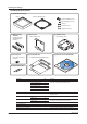
Checking the Package Checking the Accessories (1) JIS/ANSI-mounting kit Bezel Panel-mounting bracket Panel-mounting bolts (2) Bracket-fixing screws (2) Nuts (2) Flat washers (2) Spring washers (2) (2) DIN-mounting brackets (3) Dust cover (4) Terminal cover (with 1 fixing screw) (with 3 fixing screws) (for DIN 96-square instrument panel mounting) (5) Shorting bar (7) Startup Manuals (for RS-485 communication termination) (8) Manuals for the PR300 (CD) (Installation/Initial Setup Operations) er
1 Model PR300 Power and Energy Meter IM 77C01E01-01E 2 3 Contents Introduction.................................................................................................................... i Notices ..................................................................................................................... ii Checking the Package ................................................................................................ iii 4 ■ Checking the Model and Suffix Codes ..................
Contents Chapter 4 4.1 4.2 Operation for Display of Measurement Items and Measurement Method Measurement Items ............................................................................................................ 4-1 Switching Display Pattern ...................................................................................................4-2 Switching Display Pattern ...........................................................................................................
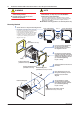
Chapter 1 Installation and Wiring 1 The PR300 can be installed so that it handles ANSI 4-inch round form or JIS 110-square instruments panel cutouts by attaching the “JIS/ANSI-mounting kit” accessory. 2 External Dimensions 110 (126.5) 104.5 Dust cover 22 2 Unit: mm (109) Installation and Wiring 1.1 Installation with the ANSI 4-inch Round Form or JIS 110-square Instrument Size 3 1.
1.1 Installation with the ANSI 4-inch Round Form or JIS 110-square Instrument Size NOTE WARNING ● Install the PR300 in the secondary side of the existing breaker. ● Provide spacing of 50 mm or more between the products. ● Do not install the PR300 in the following types of environments, as they may cause the PR300 to malfunction or fail.
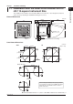
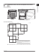
1 External Dimensions Unit: mm (124.5) 110 12.3 96 112.2 Dust cover (109) 1.5 Installation and Wiring 1.2 Installation with the DIN 96-square Instrument Size 2 3 109 96 4 Terminal cover 5 1 to 10 (Acceptable panel thickness for mounting) Mounting bracket (2 places) A Panel Cutout Dimensions 92 +0.8 0 Unit: mm (68) I 92 +0.8 0 160 min. (68) 160 min.
1.2 Installation with the DIN 96-square Instrument Size NOTE WARNING ● Install the PR300 in the secondary side of the existing breaker. ● Provide spacing of 50 mm or more between the products. ● Do not install the PR300 in the following types of environments, as they may cause the PR300 to malfunction or fail.
1.3 1 Wiring ● As there is a danger of electric shock, turn off the power supply and check that the cables to be connected are not conducting electricity before carrying out the wiring procedure. ● For safety, be sure to install a circuit breaker switch that conforms to IEC60947 near the PR300 so as to be operated easily, and clearly indicate that the device is used to de-energize the PR300. ● The wiring procedure for the PR300 should be carried out by a qualified person (an electrician etc.
1.3 Wiring Single-phase two-wire system (voltage input, current input, power supply) Power-source side 1 2 NOTE Do not ground the input circuit when connecting voltage and current directly without using VT and CT.
1.3 Wiring 1 Three-phase four-wire system (voltage input, current input, power supply) A B C (R) (S) (T) Installation and Wiring Power-source side N 1 2 3 NOTE Do not ground the input circuit when connecting voltage and current directly without using VT and CT.
1.
1 1.4 Attaching the Dust Cover and Terminal Cover NOTE Installation and Wiring ● Attach the dust cover before attaching the terminal cover. ● The recommended tightening torque for the screws for attaching the dust cover and terminal cover is 0.4N•m. 4 2 WARNING As there is a danger of electric shock, do not attach the dust cover and terminal cover while the wires are live.
Chapter 2 Preparations before Starting Measurement (Set up the PR300 First) 2.
2.2 Setting the Phase and Wire System This section explains how to set the phase and wire system by taking as an example the case when a three-phase four-wire system is changed to a three-phase three-wire system. Operation Startup screen 1 Phase and Wire System screen The Phase and Wire System screen appears. Turn on the PR300. Parameter symbol for phase and wire system Current value The PR300 shows the station number for about 5 seconds, then the Measured Value screen appears.
2.2 Setting the Phase and Wire System Startup screen The PR300 shows the Startup screen for about 5 seconds, then the Measured Value screen appears. 2 Setting completed. NOTE If you change the phase and wire system, all parameters other than those related to RS-485 and Ethernet communications are initialized (to factory-set values). Change the phase and wire system before setting parameters such as the VT and CT ratios.
2.3 Setting the Voltage Range This section explains how to set the voltage range by taking as an example the case when the voltage range is changed from 300 V to 600 V. Operation Startup screen 1 Phase and Wire System screen The Phase and Wire System screen appears. Turn on the PR300. The PR300 shows the station number for about 5 seconds, then the Measured Value screen appears. Measured Value screen 6 Using or show the Voltage Range screen. , Voltage Range screen The Voltage Range screen appears.
2.3 Voltage Range screen Setting the Voltage Range Startup screen The setpoint is confirmed and the PR300 returns to the Voltage Range screen. The voltage range thus set is shown as the current value. The PR300 shows the Startup screen for about 5 seconds, then the Measured Value screen appears. Current value When proceeding to set the phase and wire system, press or to show the Phase and Wire System screen, with this screen (figure in the upper-left corner) shown as is.
Chapter 3 Parameter Setting Operations 3.1 Basic Parameter Setting Operations NOTE Set parameters only after setting the phase and wire system and the voltage range. If you change the phase and wire system or voltage range after setting a parameter, the parameter will be initialized (to a factory-set value). Parameters related to RS-485 and Ethernet communications will not be initialized, however.
3.2 Setting the VT and CT Ratios Setting the VT Ratio This section explains how to set the VT ratio by taking as an example the case when the VT ratio is changed from the initial value (1) to 4. Operation Measured Value screen VT Ratio Setting screen To move to the digit to be changed, use the following keys: To the left 1 4 Hold down for at least 3 seconds. To the right Press once to blink the setpoint. VT Ratio Setting screen VT Ratio screen The parameter appears.
3.2 Setting the VT and CT Ratios Setting the CT Ratio This section explains how to set the CT ratio by taking as an example the case when the CT ratio is changed from the initial value (1.00) to 10.00. Operation Measured Value screen CT Ratio Setting screen 3 1 5 Hold down for at least 3 seconds. VT Ratio screen Using or , change the setpoint. CT Ratio Setting screen The parameter appears. (VT ratio) To move to the digit to be changed, use the following keys: To the left 2 Press 6 once.
3.3 Setting the Integrated Low-cut Power This section explains how to set the integrated low-cut power by taking as an example the case when the integrated low-cut power is changed from the initial value (0.05%) to 0.1%. Operation Integrated Low-cut Power Setting screen Measured Value screen To re-set the parameter: Press any key other than while all digits of the setpoint are blinking. The PR300 returns to the initial setting screen. 1 6 Hold down for at least 3 seconds.
3.3 Setting the Integrated Low-cut Power Parameter Setting Types and Ranges Parameter Symbol Parameter Name Integrated low-cut power Setting Type Setting Range (Details) Fixed-point numeric 0.05 to 20.00 (%) value Initial Value (Factory-set Value) 0.
3.4 Setting RS-485 Communication Conditions This section explains how to set RS-485 communication conditions by taking as an example the case when the protocol is changed from the initial value to Modbus/RTU. Operation Measured Value screen Protocol Setting screen The screen changes to the one for setting the parameter . Setpoint 1 6 Hold down for at least 3 seconds. Using or select the setpoint. , Protocol Setting screen VT Ratio screen The parameter appears.
3.4 Setting RS-485 Communication Conditions NOTE ● The Modbus/TCP protocol can only be selected for a PR300 with the Ethernet communication function. ● If the protocol is set to Modbus/TCP, the station number, baud rate, stop bit, and data length setpoints are fixed as shown below.
For the PR300 with Ethernet communication function only 3.5 Setting Ethernet Communication Conditions This section explains how to set Ethernet communication conditions by taking as an example the case when the IP address is changed from the initial value to “192.168.1.2”. (Ethernet communication conditions can be set only when the protocol is set to Modbus/TCP. Refer to section 3.4.
3.5 Ethernet setting switch Setting Ethernet Communication Conditions Ethernet setting switch Set the Ethernet setting switch to ON to enable the new settings. When the settings have been updated, the switch is automatically set back to OFF. To return to the Ethernet Communication Menu screen, press . To return to the Measured Value 9 screen, hold down Set the settings of parameter to ON and press .
For the PR300 with pulse output function only 3.6 Setting Pulse Output Conditions This section explains how to set pulse output conditions by taking as an example the case when the ON pulse width is changed from the initial value to 100 ms. Operation ON Pulse Width screen Measured Value screen The parameter (ON pulse width) appears. Current value 1 6 Hold down for at least 3 seconds. once.
3.6 Setting Pulse Output Conditions NOTE If the pulse unit and ON pulse width do not satisfy the following conditional expression, the updated pulse unit setpoint or ON pulse width setpoint reverts to the value before change. ON pulse width [ms] Pulse unit [kWh] 3600 10002 Primary rated power 1.
For the PR300 with analog output function only 3.7 Setting Analog Output Conditions This section explains how to set analog output conditions by taking as an example the case when the measurement item for analog output is changed to the current-1 and lower limit of scaling to 0% from their respective initial values. Operation Measurement Item for Analog Output Setting screen Measured Value screen 1 6 Hold down for at least 3 seconds. Press once to blink the setpoint.
3.7 Lower Limit of Scaling Setting screen Setting Analog Output Conditions Lower Limit of Scaling screen Lower limit of scaling setting completed. To return to the Analog Output Menu screen, press . To return to the Measured Value screen, hold down Press once while the setpoint is blinking. The setpoint is confirmed and the PR300 returns to the Lower Limit of Scalling screen. To change the upper limit of scaling, set a new limit using the parameter that follows.
For the PR300 with demand measurement function only 3.8 Setting Demand Measurement Conditions This section explains how to set demand measurement conditions by taking as an example the case when the demand alarm point is changed to 300 kW and demand alarm release function to manual release, from their respective initial values. Operation Demand Alarm Mask Time screen Measured Value screen The parameter (demand alarm mask time) appears. 1 6 Hold down for at least 3 seconds.
3.8 Demand Alarm Point screen The setpoint is confirmed and the PR300 returns to the Demand Alarm Point screen. Setting Demand Measurement Conditions Demand Alarm Release Function Setting screen Demand alarm point setting completed. 14 once. Demand Alarm Release Function screen Press once to blink the setpoint. Demand Alarm Release Function Setting screen The parameter (demand alarm release function) appears. 12 Press once.
3.9 Setting the Measured Value Display Pattern This section explains how to set the measured value display pattern by taking as an example the case when the number of display patterns is changed to 3 and the display pattern-1 upper display to maximum demand value, from their respective initial values. Operation Number of Display Patterns Setting screen Measured Value screen To re-set the parameter: Press any key other than while all digits of the setpoint are blinking.
3.9 Display Pattern-1 Upper Display screen Setting the Measured Value Display Pattern Display Pattern-1 Lower Display screen The setpoint is confirmed and the PR300 returns to the Display Pattern-1 Upper Display screen. Display pattern-1 upper display setting completed. Press 3 once. Display Pattern-1 Middle Display screen To return to the Display Setting The parameter (display pattern-1 middle display) appears. Menu screen, press . To return to the Measured Value screen, hold down .
3.
3.10 Setting the “Indicator-out” Mode and Locking Parameters Setting the Indicator-out Mode This section explains how to set the indicator-out mode by taking as an example the case when the indicatorout mode is changed to ON and the indicator-out mode wait time to 5 min, from their respective initial values. Operation Measured Value screen 3 Indicator-out Mode Setting screen while all digits of the setpoint are blinking. The PR300 returns to the initial setting screen.
3.
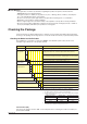
Chapter 4 Operation for Display of Measurement Items and Measurement Method 1 4.1 Measurement Items ✔ : Measurable, – : Not measurable Three-phase Single-phase Single-phase Three-phase Three-phase four-wire system two-wire system three-wire system three-wire system four-wire system (2.
4.2 Switching Display Pattern According to Display patterns-1 to 8, the PR300 can change the measurement items to be assigned to the upper, middle, and lower displays (refer to Section 3.9, “Setting the Measured Value Display Pattern”). The procedure to change the display pattern and initial values are explained below.
1 4.3 Displaying Measured, Instantaneous, and Maximum/Minimum Values 2 Example Display and Measuring Ranges of Active Power (Regenerative Power) “-” will always appear when the displayed value is a regenerative power value. Supplementary Secondary rated power 1.2 VT ratio CT ratio unit 6 W to less than 100 W (refer to the table on the right) 100 W to less than 1 kW Active power 3 0.0 to 999.9 W 1 kW to less than 10 kW 0 to 9999 W 10 kW to less than 100 kW 0.00 to 99.
4.3 Displaying Measured, Instantaneous, and Maximum/Minimum Values Example Display and Measuring Ranges of Voltage Supplementary unit (refer to the table on the right) Voltage range 1.2 VT ratio Voltage-1 Voltage-2 Voltage-3 Measuring range 100 V to less than 1 kV 0.0 to 999.9 V 1 kV to less than 10 kV 0 to 9999 V 10 kV to less than 100 kV 0.00 to 99.99 kV 100 kV to less than 1 MV 0.0 to 999.
4.3 Displaying Measured, Instantaneous, and Maximum/Minimum Values 1 Example Display and Measuring Ranges of Frequency The frequency of Voltage-1 is displayed. 2 Frequency 3 : Turns on while the maximum value is displayed. : Turns on while the minimum value is displayed. The following will appear when the measurement is out of range: 5 Measuring range: 45.0 to 65.
4.4 Phase Switching for Voltage and Current Using an operation key ( ) of the PR300, the user can switch the phase of voltage, current, and demand current (*1) for display. • For this phase switching, “Voltage (phase switch indication),” “Current (phase switch indication),” and “Demand current (*1)” must be set to the display pattern, and those settings seen on the Measured Value screen. *1 Only the PR300 with the demand measuring function can handle demand current.
1 4.5 Displaying Energy Values 2 This section explains the measuring range and display method of active energy, regenerative energy, LEAD reactive energy, LAG reactive energy, and apparent energy. Example Display and Measuring Ranges of Active Energy and Regenerative Energy 3 “-” will always appear when the displayed value is a regenerative energy value.
4.5 Displaying Energy Values Operation for Energy Value Display For all measurement ranges of active energy, regenerative energy, LEAD reactive energy, LAG reactive energy, and apparent energy, decimal places that are not appearing can be displayed by key operation. ● The digits being displayed are in in the table below. The figures that are not highlighted are not displayed and not visible. ● Every time is pressed, the display order is is pressed when the incremented by 1.
4.5 Displaying Energy Values 1 Optional Integrating Function The optional integrating function integrates the active power while the control signal for optional integration is activated (ON for activating and OFF for deactivating). The operation for this signal can be performed via communication or by digital input.
4.6 Resetting Measured Values Resetting Maximum and Minimum Values Operation Measured Value screen Reset Item Confirmation screen The Reset Item Confirmation screen appears, and the reset items blinks. To stop resetting To change the reset items 1 Press any key other than while the reset items are blinking. The PR300 returns to the Reset Item Selection screen. Simultaneously hold down and least 5 seconds.
4.6 Resetting Measured Values Canceling Reset Item Selection (Returning to the Measured Value screen without resetting) When the screen moves to the Reset Item Selection screen from the Measured Value screen, in order to return to the Measured Value screen without resetting a measured value, carry out the following operations.
4.7 Demand Measurement (Optional Measuring Function) The PR300 (with the demand measuring function) can measure the average power or current during the set demand period. This section explains the example display of measured value, measuring range, measurement operation, and example measurement. For setting conditions related to the demand measurement such as demand period, refer to Section 3.8, “Setting Demand Measurement Conditions.
4.7 Demand Measurement (Optional Measuring Function) 1 Operation for Demand Measurement Demand measurement can be started and stopped by the operation key ( ) or via communication. This section only explains control by the operation key (for operation via communication, refer to the PR300 Communication Interface User’s Manual: IM77C01E01-10E). In the demand measurement mode, either the demand power or the demand current can be measured. To set either of these, refer to Section 3.
4.7 Demand Measurement (Optional Measuring Function) Demand Alarm Demand alarm output Function: When the set demand alarm point is exceeded, an alarm is output. Output signal: Open collector Output capacity: 30 V DC, 200 mA Demand alarm release function Automatic release: When the demand value falls below the demand alarm point, the alarm is canceled. Manual release: The state of the alarm is maintained even if the demand value falls below the demand alarm point.
Chapter 5 Troubleshooting 5.1 Error Display and Recommended Response Failure at the Time of Turning on the Power and during Operation Error display Power Phase and Communi lamp wire system -cation lamp lamp Upper display of measured value display Unstable Off Off Pulse lamp Off Type of fault RAM error Status Pulse output Analog Demand Recommended Power Communiresponse (contact calculation cation output alarm point) Disabled Disabled Disabled Disabled Disabled Request repair.
5.2 Maintenance Cleaning The front panel and operation keys should be gently wiped with a dry cloth. NOTE Do not use alcohol, benzine, or any other solvents. Request for Repair in the Case of a Failure • • • In the case of a failure, the failed product is to be exchanged for a replacement. We will accept the request for repair for a period of seven years from the date of the purchase. The parameter settings set to the failed product cannot be restored for a replacement.
Appendix 1 Appendix 1 Specifications of PR300 Measuring Function Active energy (regenerative energy) The active power up to present is integrated, and the integrated value is output in units of kWh or MWh (only kWh in the communication mode). The sign of integrated values of regenerative power is “–,” and they are output as different data. Reactive energy LAG and LEAD reactive power up to present are integrated and output in units of kvarh or Mvarh (only kvarh in the communication mode).
Appendix 1 Specifications of PR300 Power Items and Equations (V and A are rms values.) Phase and wire system Apparent Power Reactive Power Power Factor (without using reactive power meter method) Single-phase two-wire system VA = V×A Single-phase three-wire system VAi = Vi×Ai Three-phase three-wire system VAi = Vi×Ai i = 1, 2 i = 1, 3 Three-phase four-wire system (2.
Appendix 1 Specifications of PR300 1 Digital Input Specifications It is used for control signals for optional integration or demand alarm release. Control signal for optional integration: Starts and stops measurement of optional active energy. Demand alarm release (with demand measuring function): Releases demand alarm. Number of inputs 1 Input signal Voltage signal; ON signal: 4.
Appendix 1 Specifications of PR300 Demand Alarm Output Specifications (optional measuring function) When the demand measurement value exceeds the set demand alarm point, an alarm is triggered.
Appendix 1 Specifications of PR300 1 Example of connection diagram Maximum distance: about 1.2 km (31 units maximum) PR300 RS-232C/RS-485 converter PR300 PR300 120 (built-in) (Aⴚ) (Bⴙ) (SG) RS-485 (Aⴚ) (Bⴙ) (SG) RS-485 (Aⴚ) (Bⴙ) (SG) RS-485 2 (TERM) (Aⴚ) (Bⴙ) (SG) PC RS-232C straight cable Terminator 120 external 3 (FG) For RS-485 communication, the PR300 employs the two-wire system.
Appendix 1 Specifications of PR300 Modbus/TCP function Code 03 06 08 16 Function Description Reads data from multiple D registers Capable of reading data from up to 64 registers continuously. Capable of writing data into one resiter. Writes data into D register Performs loopback test Writes data into multiple D registers Capable of performing a communication test. Capable of writing data into up to 32 registers continuously.
Appendix 1 Specifications of PR300 1 Insulation resistance Between each of the voltage input, current input, power, ground, digital input, pulse output, analog output, RS-485 communication output, Ethernet communication output, and alarm output terminals: 100 M minimum (at 500 V DC) Withstand voltage Between each of the voltage input, current input, power, and ground terminals: 2500 V AC for 1 minute Between (the voltage input, current input, power, and ground terminals) and the digital input, pulse ou
Appendix 1 Specifications of PR300 Environmental Conditions Normal operating conditions Warm-up time At least 30 minutes Ambient temperature 0 to 50°C (reference temperature: 23 2°C) Temperature change 10°C/h or less Ambient humidity 20 to 90% RH (no condensation) Magnetic field 400A/m or less Continuous vibration 10 to 60 Hz, 0.035 mm, 75 minutes; 60 to 150 Hz, 4.9 m/s2, 75 minutes Short-time vibration 14.
1 Appendix 2 System Reset There are two methods of performing system reset: • Turn off the power of the PR300 and then turn it on again. • Execute remote reset via communication (for remote reset, refer to the PR300 Power and Energy Meter Communication Interface User’s Manual: IM 77C01E01-10E) 2 Measured values to be reset If system reset is executed, the following measured values will be reset.
Appendix 3 Parameter Map Some of the following parameters cannot be displayed due to the specifications of the PR300. Power ON Startup screen Measured Value screen Display pattern-1 Display pattern-2 Display pattern-n (a maximum of 8 patterns) Hold down for at least 3 seconds. Hold down for at least 3 seconds. Parameter screen 1 Specification Change Confirmation screen + Go to the next screen Hold down for at least 3 seconds.
Appendix 3 Parameter Setting Procedure 1 Parameter screen 4 5 *1 5-1 5-6 5-11 5-2 5-7 5-12 5-3 5-8 5-13 5-4 5-9 5-14 5-5 5-10 2 3 4 6 To move to the previous or next step in the procedure indicated by the dotted line, use the following keys: 6-1 *2 6-2 Go to the previous screen 6-3 *1 Displayed for a PR300 with Ethernet communication and when the protocol is set to Modbus/TCP. *2 Displayed for a PR300 with pulse output. *3 Displayed for a PR300 with analog output.
Appendix 4 Parameter List Display Order Parameter Symbol Parameter Name Setting Type Setting Range (Details) Integral numeric 1 to 6000 value Floating-point numeric 0.05 to 32000 value Fixed-point numeric 0.05 to 20.00 (%) value 1 VT ratio 2 CT ratio 3 Integrated low-cut power 4 RS-485 communication menu 4-1 Station number Integral numeric value 4-2 Protocol Selection Initial Value (Factoryset Value) MEMO 1 1.00 0.
Appendix 4 Parameter List Display Order Parameter Symbol Parameter Name 5-8 Subnet mask-4 5-9 Default gateway-1 5-10 Setting Type Integral numeric value Setting Range (Details) Initial Value (Factoryset Value) 0 to 255 0 0 to 255 0 Default gateway-2 0 to 255 0 5-11 Default gateway-3 0 to 255 0 5-12 Default gateway-4 0 to 255 0 5-13 Port number 5-14 Ethernet setting switch 6 Pulse output menu (Displayed only for a PR300 with pulse output.
Appendix 4 Display Order Parameter List Parameter Symbol Parameter Name Setting Range (Details) Initial Value (Factoryset Value) 1 to 60 (min) (Demand alarm mask time to 60) (min) 30 1 to 59 (min) (1 to demand period) (min) 1 Setting Type Integral numeric value Integral numeric value Integral numeric value 8-2 Demand period 8-3 Demand alarm mask time 8-4 Demand alarm point 8-5 Demand alarm release function 9 Display setting menu 9-1 Indicator-out mode 9-2 Indicator-out mode wait time
Appendix 4 Parameter List Display Order Parameter Symbol Setting Type Parameter Name Setting Range (Details) Initial Value (FactoryMEMO set Value) Current (phase switch indication) Voltage (phase switch indication) 9-19 Display pattern-6 upper display 9-20 Display pattern-6 middle display 9-21 Display pattern-6 lower display Frequency 9-22 Display pattern-7 upper display Current (phase switch indication) 9-23 Display pattern-7 middle display Active power 9-24 Display pattern-7 lower disp
Appendix 5 Alphanumeric Characters Table for 7-segment LED The PR300 uses a 7-segment LED as its display. It displays alphanumeric characters according to the table below (however, the table also contains characters that are not used by the PR300). 0 A J T 1 B K U 2 C L u 3 D M V 4 E N W 5 F O X 6 G P Y 7 H Q Z 8 h R 9 I S NOTE The PR300 displays H and U in two different forms (uppercase and lowercase) for easy viewing.
Index Index A O Analog output conditions setting ....................................... 3-12 Optional integrating function ............................................... 4-9 C P Component names and functions ....................................... 2-1 CT ratio setting .................................................................... 3-3 Panel cutout dimensions ANSI ............................................................................... 1-1 DIN ...........................................
W Wiring diagram Single-phase two-wire system ........................................ 1-6 Single-phase three-wire system ..................................... 1-6 Three-phase three-wire system ...................................... 1-6 Three-phase four-wire system ........................................ 1-7 Three-phase four-wire system (2.5 element) .................. 1-7 Analog output ................................................................. 1-8 Demand alarm output ...............................
YOKOGAWA ELECTRIC CORPORATION Headquarters 2-9-32, Nakacho, Musashino-shi, Tokyo, 180-8750 JAPAN Branch Sales Offices Nagoya, Osaka, Hiroshima, Fukuoka, Sapporo, Sendai, Ichihara, Toyota, Kanazawa, Okayama, and Kitakyusyu. YOKOGAWA CORPORATION OF AMERICA 2 Dart Road, Newnan, Georgia 30265-1094, U.S.A. Phone : 1-800-888-6400 Fax : 1-770-254-0928 YOKOGAWA EUROPE B. V.