User’s Manual Models 436101/436102/436103/436104/436106 µR10000 Recorder Portable Type * 4 P 1 B 1 5 1 E 0 1 * IM 04P01B01-51E Yokogawa Electric Corporation 1st Edition
Foreword Thank you for purchasing the µR10000 (hereafter referred to as recorder). This user’s manual contains information about the recorder with the /H5x option specification (the portable type). Please also refer to the user’s manual for the standard version of the recorder (IM04P01B01-01E) when operating this model. Notes • The contents of this manual are subject to change without prior notice as a result of continuing improvements to the instrument’s performance and functions.
Safety Precautions The following describes warnings that are specific to the portable type. Please also refer to pages iii and iv of IM04P01B01-01E for warnings that apply to all models of the recorder. WARNING • Power Supply Before connecting the power cord, ensure that the power supply voltage matches the voltage rating for the instrument, and that it is within the maximum rated voltage for the power cord itself.
Checking the Contents of the Package Unpack the box and check the contents before operating the software. If some items are missing or otherwise inconsistent with the contents description, please contact your dealer or nearest YOKOGAWA dealer. Checking the Model Name Check the name plate on the recorder to ensure that the model name and suffix code match the ones you ordered. RECORDER MODEL SUFFIX STYLE SUPPLY FREQUENCY NO. TAG NO.
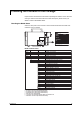
Checking the Contents of the Package Standard Accessories Power cord /H5D /H5F /H5J /H5R /H5H One of these power cord types is supplied according to the instrument’s suffix code Part Number Q’ty Note A1006WD 1 Provided when /H5D is specified for the optional code. Maximum rated power voltage: 125V A1009WD 1 Provided when /H5F is specified for the optional code. Maximum rated power voltage: 250V A1024WD 1 Provided when /H5R is specified for the optional code.
Installation and Connecting the Power Supply Installation The following describes warnings that are specific to the portable type. For all other details regarding installation, see section 2.2 of IM04L01B01-01E, “Installation.” Precautions Regarding the Installation Location • The portable type is not equipped to be installed in an instrumentation panel. • For the portable type, we recommend that you maintain a 50 mm or greater margin of space around the front, back, sides, and top of the instrument.
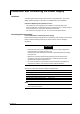
Installation and Connecting the Power Supply Connections 1. Check that the power switch to the instrument is turned OFF. 2. Connect the plug on the accessory power cord to the power supply connector on the rear panel. ~ 0V 24 z X 0- 0H A 10 0/6 M 5 VA 40 3.
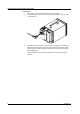
Names of Parts The following describes only the names of parts that are specific to the portable type. For all other part names, see section 3.1 of IM04P01B01-01E, “Names of Parts and Functions.” 1 10 0 40 50/60 -240 VA H V~ MA z X RE . NO TAG E RD COYLE R ST L DE MO FIX F SU R US C 2608 17 0 N2 SU PP LY EQ FR . NO UE NC na Y e in Chi Mad 0 1. Carrying handle 2. Protective ground terminal (spare) 3. Power terminal with protective ground terminal (attach the specified power cord) 4.
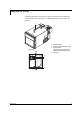
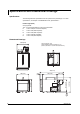
Specifications and Dimensional Drawings Specifications The following describes specifications that are specific to the portable type. For other specifications, see chapter 12 of IM04P01B01-01E, “Specifications.” Portable Type (/H5x) Carrying handle The “x” in /H5x designates the power cord specification. D: Power cord (UL and CSA compliant) F: Power cord (VDE compliant) R: Power cord (SAA compliant) J: Power cord (BS compliant) H: Power cord (GB compliant) Dimensional Drawings 138.5 (5.