Operation Guide Models 436101/436102/436103/436104/436106 µR10000 Recorder IM 04P01B01-02E Yokogawa Electric Corporation 5th Edition
User Registration Thank you for purchasing YOKOGAWA products. We invite you to register your products in order to receive the most up to date product information. To register, visit the following URL. http://www.yokogawa.
Contents Safety Precautions......................................................................................................................................................4 Handling Precautions..................................................................................................................................................5 How to Use This Manual.............................................................................................................................................
Thank you for purchasing the YOKOGAWA µR10000 Recorder. This manual describes concisely the operating procedures of the µR10000 Recorder. To ensure correct use, please read this manual thoroughly before beginning operation. The following two manuals, in addition to this one, are provided as manuals for the µR10000 Recorder. Please read all of them. Safety Precautions The general safety precautions described here must be observed during all phases of operation.
WARNING • Exemption from Responsibility • YOKOGAWA makes no warranties regarding the product except those stated in the WARRANTY that is provided separately. • YOKOGAWA assumes no liability to any party for any loss or damage, direct or indirect, caused by the user or any unpredictable defect of the product. • Handling Precautions of the Software • YOKOGAWA makes no warranties regarding the software accompanying this product except those stated in the WARRANTY that is provided separately.
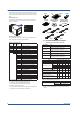
Checking the Contents of the Package Unpack the box and check the contents before operating the instrument. If some of the contents are not correct or missing or if there is physical damage, contact the dealer from which you purchased them. µR10000 Recorder A name plate is affixed to the case. Check that the model name and suffix code given on the name plate on the rear panel match those on your order.
Optional Accessories (Sold Separately) The optional accessories below are available for purchase separately. If you make an order, make sure that all contents are present and undamaged. For information about ordering accessories, contact the dealer from which you purchased the recorder.
Recorder’s Version and Functions Described in This Manual The contents of this manual corresponds to the recorder with version 1.31. µR10000 Versions and Functions Version 1.02 or earlier 1.11 Suffix Code – – – – – 1.21 /C3 /C7 -2 /CC1 1.31 /H5x /P1 – – /BT1 Added or Modified Functions – (Added) The printout/display format of the date can be changed. Reference – Sec. 7.
Function Introduction/Names of Parts Function Introduction The µR10000 Recorder (hereafter referred to as the recorder) can be used to assign DC voltage, 1-5V, thermocouple, RTD, and contact or voltage ON/OFF signal to channels for measurement. The measured results are recorded with pens or dots on a chart paper that is fed at a constant speed. The pen model can record up to 4 channels; the dot model can record up to 6 channels.
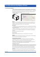
Function Introduction/Names of Parts Names of Parts Front Name plate The model name is written on the name plate. Display and key panel Hold the tab at the lower left and pull to open. Door Tag plate Used to write channel names. Mounting hole There is one hole on each of the top, bottom, left, and right panels. The hole is covered with a seal. Chart cassette Holds the chart paper. Power switch Turns ON/OFF the power each time the switch is pressed.
Function Introduction/Names of Parts Display and Key Panel Status display Displays the following information. RECORD Illuminates while recording measured values. KEY LOCK Illuminates when key lock is enabled. MATH Illuminates when computation on the computation function (/M1 option) is in progress. CHART END Illuminates when the chart paper is out (/F1 option). ALARM 1 to 6 Illuminates when an alarm is occurring on channels 1 to 6. Main display Displays the measured values.
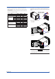
Installing/Wiring the Recorder Installation Location Install the recorder indoors in a location that meets the following conditions. • Instrument Panel The recorder is designed for panel mounting. The portable type (/H5x option) is designed to be used on the desktop. • Well-Ventilated Location To prevent overheating, install the recorder in a well-ventilated location. For the panel cut dimensions when arranging multiple recorders, see page 14.
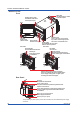
Installing/Wiring the Recorder • The proper torque for tightening the mounting screws is 0.7 to 0.9 N•m. • Mount the recorder to the panel according to the procedure below. • First, attach the two mounting brackets and temporarily fasten the attachment screws. • Next, fix the recorder in place by tightening the attachment screws with the appropriate torque.
Installing/Wiring the Recorder Panel Cutout Single-Unit Mounting Side-by-Side Mounting (vertically, max. 3 units) Side-by-Side Mounting (horizontally) +2 +2 137 0 (5.39) 137 0 (5.39) 137 +2 0 (5.39) 175 min. (6.89) 137 +2 0 (5.39) L L +2 0 Attach the mounting brackets to the top and bottom when mounting the recorders side-by-side horizontally or right and left when mounting the recorders side-by-side vertically. Unit: mm (approx.
Installing/Wiring the Recorder Input Signal Wiring WARNING • To prevent electric shock while wiring, ensure that the power supply source is turned OFF. CAUTION • The input terminals of this instrument are specific to this instrument. Do not connect the input terminals of the µR1000, µR1800 or other models, as malfunction may result. • If a strong tension is applied to the cable wired to the recorder, the terminals of the recorder and/or the cable can be damaged.
Installing/Wiring the Recorder Measuring input terminal block Wiring Procedure A terminal cover is screwed in place on the measuring input terminal block on the rear panel. A label indicating the terminal arrangement is affixed to the cover. 1. Turn OFF the recorder and remove the terminal cover. Terminal cover attachment screws 2. Connect the signal wires to the terminals. Note Input signal wires of diameter less than or equal to 0.3 mm may not be secured firmly for clamped terminals (/H2).
Installing/Wiring the Recorder Optional Terminal Wiring WARNING • To prevent electric shock while wiring, ensure that the power supply source is turned OFF. • If a voltage of more than 30 VAC or 60 VDC is to be applied to the output terminals, use ring-tongue crimp-on lugs with insulation sleeves on all terminals to prevent the wires from slipping out when the screws become loose.
Installing/Wiring the Recorder /A1 NO C NC I01 NO C NC I02 /A1/F1 (/F1) NO C NC I01 NO C NC I02 NO C NC CE NO C NC FAIL /A1/R1 NO C NC I01 NO C NO NO /A2/F1 NO C NC I02 1 2 3 4 5 C /A2/R1 NC CE C NC FAIL 1 2 3 4 5 C NC I01 NC I02 C NC I03 NO C NC I03 NO C NC I03 NO C NC I04 NO C NC I04 NO C NC I04 NO C NC CE NO C NC CE NO C NC FAIL NO C NC FAIL 1 2 3 4 5 C (/F1) /A3/R1 1 2 3 4 5 C (/R1) /F1 NO C NC I01 NC I02 NO
Installing/Wiring the Recorder Power Supply Wiring WARNING Panel Mount Type • To prevent electric shock when wiring, ensure the main power supply is turned OFF. • To prevent the possibility of fire, use 600 V PVC insulated wire (AWG20 to 16) or an equivalent wire for power wiring. • Make sure to earth ground the protective earth terminal through a grounding resistance less than 100 Ω before turning ON the power. • Use crimp-on lugs (designed for 4-mm screws) for power and ground wiring termination.
Installing/Wiring the Recorder Wiring Procedure (Panel Mount Type) The power supply terminals and protective ground terminals are located on the rear panel. 1. Turn OFF the power switch on the recorder and open the power terminal cover. 2. Wire the power cord and the protective ground cord to the power supply terminals. Use ring-tongue crimp-on lugs (designed for 4-mm screws). 3. Close the power supply terminal cover and secure it with the screw. The proper torque for tightening the screws is 0.6 N•m.
Common Operations and Menu Structure Execution Modes The recorder has three execution modes. Operation Mode This mode is used for normal recording operation. The recorder enters this mode when the power is turned ON. Setting Mode This mode is used to set the input range, alarms, chart speed, and other parameters. These settings can be changed while recording is in progress.
Common Operations and Menu Structure Key Operation Entering Setting Mode Hold down the MENU key for 3 seconds. The Setting mode display appears. The top and bottom lines are the setup item and comment, respectively. The section that is blinking is the setup item that you change. In this manual, the section that you change appears shaded. Setup item Comment Set=Range Input range and The item to be controlled blinks. In Setting mode, the panel keys are set to the functions marked above the keys.
Common Operations and Menu Structure Changing the Settings Note The comment line shows useful information such as a description of the setup item and the range of selectable values. Read the comment and change the items as necessary. The selected item change each time you press the ( DISP ) key. The selected item change in reverse order if you press the ( DISP ) while holding down the SHIFT ( FEED ) key.
Common Operations and Menu Structure The character type changes each time you press the CHARACTER ( MENU ) key. The character type changes in reverse order each time you press the SHIFT ( FEED ) + CHARACTER ( MENU ) key. The character types change in the following order: uppercase alphabet (A-Z), lowercase alphabet (a-z), numbers (0-9), and symbols (%-.). A-Z a-z 0-9 %-. A to Z, and space a to z, and space 0 to 9, and space %, #, °, @, +, –, *, /, (, ), µ, Ω, 2, 3, .
Common Operations and Menu Structure Menu Structure of Setting Mode References to the µR10000 Recorder User’s Manual (IM 04P01B01-01E) are given in parentheses. Range (section 5.1) CH Volt Range Span_L Span_R TC Range Span_L Span_R RTD Range Span_L Span_R 1-5V Span_L Scale Type Delta Ref.CH DI Range Span_L Span_R SQRT Range Span_L Span_R Span_R Range Recorder version: 1.
Common Operations and Menu Structure Menu Structure of Basic Setting Mode References to the µR10000 Recorder User’s Manual (IM 04P01B01-01E) are given in parentheses. Recorder version: 1.31 Alarm (section 7.1) A/D (section 7.2) Diagnosis Reflash AND RJC CH RJC Color Channel POC POC Print CH/Tag Channel Alarm Print 1 Periodic Ref.Time Interval Print 2 CH Mode Bar graph CH Graph (section 7.6) (section 7.7) (section 7.8) (section 7.8) (section 7.
Preparing to Record Loading or Replacing the Chart Paper CAUTION • Do not install or remove the chart cassette with the chart paper guide open. This may damage the stopper. • Continuing to record or print without the chart paper on the dot model can cause damage to the chart cassette platen (the cylindrical section that holds the paper during the recording operation). Be sure to replace the chart paper ahead of time.
Preparing to Record 4. Load the chart paper. Riffle the chart thoroughly before loading. Make sure that the sprocket teeth of the chart drives are properly engaged in the chart paper perforations. Make sure not to load the chart paper backwards. Z-fold chart paper Sprocket teeth 5. Close the chart holder and close the chart paper guide. Chart holder Chart paper guide The side with the long rectangular holes is the right side. 6. Replace the chart cassette back into the recorder.
Preparing to Record Installing/Replacing Felt Pens (Pen Model) CAUTION • • • • Do not press or pinch the felt tip to prevent deformation. Do not move the penholder left or right by force to protect the driving mechanism. Make sure to remove the pen cap before installation. Use pen caps of the same ink color. If a pen cap of a different ink color is used on the pen, the remaining ink in the cap may be absorbed through the pen tip, and the ink may change its color. 1. Open the door.
Preparing to Record Installing/Replacing the Plotter Pen (Pen Model) 1. Open the door. If recording is in progress, press the RCD key to stop the recording. 2. Open the display and key panel section. 3. Hold the plotter pen cartridge and pull it out from the pen holder. 4. Remove the cap from the new plotter pen and insert the pen firmly into the pen holder. 5. Return the display and key panel section to its original position.
Preparing to Record 6. Remove the ribbon cassette. Pull the left-hand part of the ribbon cassette so that the cassette holder tab disengages, and pull the ribbon cassette out from the recorder case. Holder tab Ribbon cassette 7. Install a new ribbon cassette. First, insert the right-hand part and then the left-hand part into the cassette holder. Check that the cassette is properly engaged with the cassette holder tab.
Preparing to Record Checking or Setting the Date/Time Checking the Date/Time The date/time is shown on the display when the DISP key is pressed several times. Setting the Date/Time 1. Hold down the MENU 2. Press the key to show Clock and then press the key for 3 seconds to enter Setting mode. 3. Set the date and time and press the key. Set=Clock 04/01/17 Press the value. 10:39:47 key. Year/Month/Day Hour:Minute:Second key to select the desired digit.
Setting the Input Range and Alarm on Measurement Channels Setup Example (1) of Thermocouple Input Set channel 02 to thermocouple type K and measure temperatures in the range –50.0 to 450.0°C. The measurable range for thermocouple type K is –200.0 to 1370.0°C. The measured values in the range of –50.0 to 450.0°C are recorded in a width of 100 mm on the chart paper.
Setting the Input Range and Alarm on Measurement Channels Setting Span Right 8. Likewise, set Span_R to 450.0 and press the Span_R= -200.0/ key. 450.0 1370.0°C The Setting complete screen is displayed. When this screen is displayed, the settings entered up to then are applied. Finishing the Settings 9. When Setting complete screen is displayed, do either of the following: key to set other channels. Press the To finish setting the input range, press the ESC key.
Setting the Input Range and Alarm on Measurement Channels Selecting the Input Type 5. Press the key to select 1-5V and then press the key (see “Explanation” on page 38). Mode=1-5V Scales and record Setting Span Left 6. Set Span_L to 1.000 and press the key. key to select the desired digit. Press the Press the value. Span_L= 0.800/ 1.000 1.200V key to select the Displays the range of Span_L. Setting Span Right 7. Likewise, set Span_R to 5.000 and press the Span_R= 4.800/ 5.
Setting the Input Range and Alarm on Measurement Channels Selecting the Unit 16. Use the CHARACTER key and key to set unit character and then press the key. (For the procedure, see “Entering Characters” on page 23. For the characters that can be used, see “Explanation” on page 38). Unit: CHR:%- Finishing the Unit Setting 17. When Setting complete screen is displayed, press the ESC key. 03-03 Channel Setting complete 18. Hold down the MENU key for 3 seconds to return to Operation mode.
Setting the Input Range and Alarm on Measurement Channels Selecting the Input Type 5. Press the key to select Scale, and press the settings, see “Explanation” on page 38). key (for the selectable Mode=Scale Scales and record 6. Press the key to select Volt and then press the key. Type=Volt DC Voltage 7. Press the key to select 20V and then press the key. Range=20V 20mV-50V Setting Span Left 8. Set Span_L to 0.00, and press the key. key to select the desired digit.
Setting the Input Range and Alarm on Measurement Channels Explanation Note If the range is changed after setting the alarm, the alarm setting becomes invalid. When you change the range, check the alarm setting. In step 5 of setup examples (1), (2), and (3), you can select an input type or a computation type on the table below.
Setting the Input Range and Alarm on Measurement Channels Setting the Alarm Setup Example Set a high limit alarm at 400.0°C on channel 02. The relay output (option) is not available. Entering Setting Mode 1. Hold down the MENU key for 3 seconds to enter Setting mode. Selecting the Channel 2. Press the key with Alarm shown on the screen. Set=Alarm Alarm setting 3. Press the Displays a description of the setup item. key to set the first channel to 02 and then press the key.
Setting the Input Range and Alarm on Measurement Channels Finishing the Settings 10. When Setting complete screen is displayed, do either of the following: key to set other alarms. Press the To finish setting the alarm, press the ESC key. 02-02 CH/level 1 Setting complete 11. Hold down the MENU key for 3 seconds to return to Operation mode. Explanation In step 7, you can select an alarm type on the table below.
Recording/Displaying Data Starting the Recording Press the RCD key to start recording. The status display shows the word “RECORD.” Note For models with the FAIL/chart end detection and output function (/F1 option), the chart feed will not start even when pressing the RCD key if the chart paper is empty or almost out. Insert new chart paper before pressing the RCD key.
Recording/Displaying Data Changing the Chart Speed 1. Hold down the MENU 2. Press the key to show Chart and then press the key for 3 seconds to enter Setting mode. Set=Chart Chart speed key. Displays a description of the setup item. 3. Set the chart speed and press the key. Current chart speed. Displays the range that can be specified. (Display example on the dot model) mm/h= 20 1/1500mm/h On the pen model, press the key to select the chart speed.
Recording/Displaying Data Description of the Printout Contents Printout Description Figure (Pen Model) Manual printout Nov.09.04 15:00 1 223.5mg/cm3 3 H 591.6°C 2 4 437.2µS/cm -0.222V New chart speed printout 50mm/h 14:55 Periodic printout Time tick cancel mark Nov.09.04! 13:50* Pen offset compensation mark 1 218.7mg/cm3 2 390.6µS/cm 3 H 598.4°C 4 d -0.222V 0.0 1CH Alarm RED Delta computation 50mm/h_ Scale 500.
Recording/Displaying Data The printout description figures are for explaining the printout contents. The font is different from the actual printout. The printout positions are also slightly different. • Manual Printout Prints the current measured values and alarm statuses of all channels by operating the keys. • New Chart Speed Printout When the chart speed is changed, the time tick (dot model), the date/time of change, and the new chart speed are printed.
Recording/Displaying Data Switching the Display Screen The screen switches each time the DISP key is pressed. Screen 01 through 15 are switched in order. Screens that are set to “Skip” (See “Display Types” on the next page) are skipped. Below is a display example.
Recording/Displaying Data Changing the Displayed Information Different display types can be registered to screens 01 to 15. As an example, the procedure of assigning 1-channel digital display (tag display) to screen 02 is explained below. 1. Hold the 1 MENU key for 3 seconds to show the data display setup screen. Selecting the Screen Number 2. Press the key to select screen number 02 and then press the Screen No.=02 key. Displays the current display type name.
Recording/Displaying Data FUNC Key Operations in Operation Mode The operations below can be carried out with the FUNC key in Operation mode. References to the µR10000 Recorder User’s Manual (IM 04P01B01-01E) provided on the CD-ROM are given in parentheses. : Use the FUNC key : Use the key. Recorder version: 1.31 key. Alarm output release operation. This is displayed when the settings are changed to use the alarm ACK operation. Alarm ACK (section 3.12) Math (section 9.
Recording/Displaying Data Aborting the Manual Printout 1. Press the FUNC 2. Press the key. key to select Print out and then press the key. 3. Press the key with Manual Stop shown on the screen. Manual printout stops. The screen returns to the data display screen. Print=Manual Stop Printing the Recorder Settings This section explains the procedure for printing the recorder settings. There are two sets of settings that can be printed: List and Setup.
Recording/Displaying Data Clearing the Alarm Printout Buffer Alarm information waiting to be printed is temporarily stored in the buffer memory. This operation clears all of the alarm information in the buffer. This function can be used to prevent unneeded alarm printouts from being executed. 1. Press the FUNC 2. Press the key. key to select Buffer clear and then press the Func=Buffer key. clear 3. Press the key with Alarm shown on the screen.
Recording/Displaying Data Releasing the Alarm Output (Alarm ACK Operation) This operation releases the alarm indication or relay output (/A1, /A2, or /A3 option) when the alarm indication or output relay is set to hold operation. For details on the hold operation, see section 1.3, “Alarms” in the µR10000 Recorder User’s Manual (IM 04P01B01-01E) on the CD-ROM. 1. Press the FUNC key. 2. Press the key with Alarm ACK shown on the screen. The alarm indication or relay output is released.
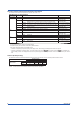
Setup Items and Default Values Setup Items in Setting Mode and Their Default Values (Recorder version: 1.31) The items with an asterisk are not displayed in the default condition. To display these items, settings must be changed in Basic Setting mode.
Setup Items and Default Values Setup Item Aux > DST Aux > DST > Start month Pen/Dot - Aux > DST > Start day Aux > DST > Start time Aux > DST > End month - Aux > DST > End day Aux > DST > End time Math (/M1 option) Math > Formula > CH Math > Formula > Mode Math > Formula > f. Math > Unit > CH Math > Unit > Unit Math > Constant > No. Math > Alarm > CH Math > Alarm > Level Math > Alarm > Alarm Math > Alarm > Type Math > Alarm > Value Math > Alarm > Relay Math > Alarm > Relay No.
Setup Items and Default Values Setup Items in Basic Setting Mode and Their Default Values (Recorder version: 1.
Setup Items and Default Values Setup Item Personalize > Add function > Bias Personalize > Add function > SQRT low-cut Personalize > Add function > 1-5V low-cut Personalize > Add function > Alarm delay Personalize > Add function > Calibration Personalize > Time print > Alarm Pen/Dot - Personalize > Time print > Message - Personalize > Time print > RCD On - Personalize > Time print > C.
Setup Items and Default Values Setup Item Ethernet > DNS > S Ethernet > DNS > Suffix_P Ethernet > DNS > Suffix_S Ethernet > Login > Login Ethernet > LoginSet > Level Ethernet > LoginSet > Register Pen/Dot - Selectable Range or Selections IP address (Secondary DNS sever) Primary domain suffix Secondary domain suffix Use/Not Admin/User1 to User6 On/Off Ethernet > LoginSet > User - 16 characters or less Ethernet > LoginSet > Password - 4 characters or less Ethernet > Timeout > Timeout Ethernet > Timeo
Recommended Replacement Periods for Worn Parts To preserve the reliability of the recorder and to use the recorder in good condition for an extended time, it is recommended that periodic replacements be made on parts. The replacement parts may change to accommodate preventive maintenance over extended time. Be sure to check with your nearest YOKOGAWA dealer. The table below shows the recommended replacement period for expendable parts.