Service Manual Model 437101/437102/437103/437104/ 437106/437112/437118/437124 µR20000 SM 04P02B01-01E Yokogawa Electric Corporation 1st Edition
Important Notice to the User • This manual contains information for servicing YOKOGAWA’s µR20000. Check the serial number to confirm that this is the correct service manual for the instrument to be serviced. Do not use the wrong manual. • Before any maintenance and servicing, read all safety precautions carefully. • Only properly trained personnel may carry out the maintenance and servicing described in this service manual.
Introduction This manual contains information for servicing YOKOGAWA’s µR20000. Note This is the first edition of the manual, dated March 2006. WARNING This service manual is to be used by properly trained personnel only. To avoid personal injury, do not perform any servicing unless you are qualified to do so. Refer to the safety precautions prior to performing any servicing.
WARNING • Power Supply Ensure that the source voltage matches the voltage of the power supply before turning ON the power. • Protective Grounding Make sure to connect the protective grounding to prevent electric shock before turning ON the power. • Necessity of Protective Grounding Never cut off the internal or external protective earth wire or disconnect the wiring of the protective earth terminal. Doing so invalidates the protective functions of the instrument and poses a potential shock hazard.
Overview of This Manual This manual is meant to be used by qualified personnel only. Make sure to read the safety precautions at the beginning of this manual as well as the warnings and cautions contained in the chapters relevant to any servicing you may be carrying out. This manual contains the following chapters. Chapter 1 Principles of Operation Describes the principles of operation of the recorder. Chapter 2 Troubleshooting Lists problems that can occur and gives corrective actions.
Contents 1 Important Notice to the User ........................................................................................................... i Trademarks ..................................................................................................................................... i 2 Introduction ...................................................................................................................................... ii Safety Standards and EMC Standards .......................
Contents Chapter 4 Adjustments 4.1 Before Making Adjustments ............................................................................................. 4-1 Environment ..................................................................................................................... 4-1 Operations on the Main Unit ............................................................................................ 4-1 Preparation ................................................................................
Chapter 1 Principles of Operation 1.1 Principles of Operation 1 Principles of Operation The following explains the principles of operation of the µR20000.
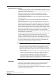
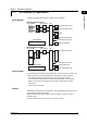
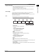
1.1 Principles of Operation A/D Converter ASIC Uses a proprietary one-chip ASIC. The ASIC is a combination analog/digital IC that contains popular CMOS processes. The table below shows its configuration. Temperature Sensor RJC Amp BiCMOS Analog CMOS Digital Multiplexer UART PGA Volt, TC A/D RTD Digital Filter Vref Controller RTD Amp Scanner Control EEPROM • Controller Controls switching of the input signal by the scanner, and switching of the A/D converter attenuator and RTD/TC mode.
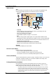
1.1 Principles of Operation 1 Display / Panel Keys Principles of Operation • Offers a variety of display types, with a fluorescent character display tube (VFD) of 181 dots (horizontal) x 16 dots (vertical). • Seven keys are available for operation and settings. • White LEDs are installed for illuminating the z-fold chart paper. The LED can be replaced. Power Supply A universal type power supply unit supplying a voltage of 100 V to 240 VAC at a frequency of 50/60 Hz.
Chapter 2 Troubleshooting 2.1 Failure Analysis and Repair Procedures This section describes failure analysis and repair procedures. 2 1. 2. 3. 4. Determine the type of problem. Check for possible user error. Check the connections and the settings of equipment to determine whether there was a handling mistake. Execute the self diagnostic test by turning the power ON, and identify any problem items. Analyze the cause of the problem according to the troubleshooting flow chart.
2.2 Failures and Corrective Actions The table below describes the most common types of failures and their corrective actions. Action Replace No power Adjust 1 Phenomenon Check No.
2.2 Failures and Corrective Actions Action 12 (Dot Model) Ribbon does not feed. 13 (Dot Model) Printed colors bleed. 14 (Dot Model) Trend recording not normal. 15 (Dot Model) Print quality poor 16 (Dot Model) Does not print. 17 Chart paper does not feed. 18 Internal illumination dim. 19 Internal illumination does not turn ON. 20 The measured value is not correct 21 Measured values fluctuate. 22 Voltage measurement is good, but temperature measurement is not correct.
Chapter 3 3.1 Testing Acceptance Test This section describes the procedure to perform the acceptance test. 1. 2. SM 04P02B01-01E 3-1 3 Testing 3. 4. 5. Read the preface to the user’s manual, “Checking the Contents of the Package” and verify that you have all of the contents. Make sure to understand the operating procedures as described in the user’s manual. Check each function using the user’s manual. Read and implement section 3.2, “Self Diagnostic Test.” Read and implement section 3.
3.2 Self Diagnostic Test The recorder is provided with complete self diagnostic functions to enhance reliability in measurement and serviceability. When you turn ON the power, the recorder will automatically execute the following types of diagnoses alternately and display the results. After these tests are completed, the recorder is ready for use. 1. 2. 3. 4. 5. 6.
3.3 Performance Tests Read the warning and cautions below before beginning tests. WARNING 3 Testing • Circuit patterns of the printed circuit board are exposed. Be careful when handling so that hands or fingers are not injured by the protruding pins. CAUTION • Circuit patterns of the printed circuit board are exposed. If other metallic materials touch these patterns, electrical shorting will occur, causing the circuit to be damaged or burnt.
3.3 Performance Tests Key Operations on the Recorder The recorder has the following modes. The following is an explanation of how to enter and exit each mode. • Operation Mode The mode in which the instrument is operated. The instrument enters this mode when the power is turned ON. • Setting Mode This mode is for entering the input range, alarms, and other settings. • Hold down the MENU key for three seconds or longer while in operation mode to enter this mode.
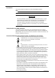
3.3 Performance Tests The Test/Adjustment Mode Menu (Pen Model) A/D Adjust Display A/D No. After specifying the range, check/change the adjustment value. Password (7098) Cal/Exec A/D No. After specifying the range, perform the adjustment. End A/D No. Store Abort Vref Password (6301) Cal/Exec A/D No. Offset End A/D No. Store 3 Testing Aux Range 20mVZ, 20mVF, 60mVZ, 60mVF, 200mVZ, 200mVF, 1VZ, 1VF, 2VZ, 2VF, 6VZ, 6VF, 20VZ, 20VF, Pt100Z, Pt100F, Cu10Z, Cu10F, Pt50Z, Pt50F F.
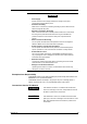
3.3 Performance Tests The Test/Adjustment Mode Menu (Dot Model) A/D Adjust Display A/D No. After specifying the range, check/change the adjustment value. Password (7098) Cal/Exec A/D No. After specifying the range, perform the adjustment. End A/D No. Store Abort Aux Vref Password (6301) Range 20mV, 60mV, 200mV 1V, 2V, 6V, 20V, Pt100, Cu10, Pt50 Cal/Exec A/D No. Offset End A/D No. Store F.Adjust Abort Rib. shift Exec R.Adjust End Store Abort ID ID Serial No.
3.3 Performance Tests Tests The following is a list of the tests of the µR20000.
3.4 Test Procedures Insulation Resistance ● Procedures Perform a measurement with an insulation tester and check whether the results meet the criteria. Perform the measurement with the power switch turned ON. Criteria Terminals Measured Criteria Between the power and earth terminals 100 MΩ or more Short the L and N terminals. Between the input and earth terminals 100 MΩ or more Short all input terminals.
3.4 Test Procedures Withstand Voltage ● Procedures Perform the test with a withstanding voltage tester, and check whether the results meet the criteria. Perform the measurement with the power switch turned ON. Test Duration The test duration is one minute. Criteria 3 Applied Voltage Max Allowable Condition Leak Current Between the power and earth terminals 1.5 kVAC*1 5 mA Short the L and N terminals. Between the input and earth terminals 1.0 kVAC 1 mA Short all input terminals.
3.4 Test Procedures ● Procedures Warm up the instrument for thirty minutes before performing the test. Set the ranges on the recorder, and input the values determined for each range. Check whether the displayed measured values meet the criteria. DC voltage generator L N + – To the input terminals Variable resistors The resistance of three lead wires must be equal.
3.4 Test Procedures Channel-to-Channel Error ● Procedures Pen Model Assign inputs as shown in the table below in parallel to channels 1 and 2, and check whether the measured values on both channels meets the criteria. Perform the same test using channels 3 and 4. Criteria Range Input 3 Criteria Short +/A and −/B 0.00 ±0.01 mV Pt100 103.9 Ω 10 ±0.2°C, between channel dispersion within 0.
3.4 Test Procedures Reference Junction Compensation Accuracy ● Procedures Set all channels to thermocouple type T. Measure 0°C on one of the channels and check that the display is within the criteria below. Criterion: 0.3°C to −0.4°C Calibrated thermocouple wires –/B +/A L N 0°C standard temperature device (Model: ZC114 from Coper Electronics Co., Ltd. or equivalent) Input terminals • Use a calibrated thermocouple, and wires of 0.5 diameter or less without a terminal chip.
3.4 Test Procedures Keys ● Procedures 1. 2. 3. Turn ON the power switch while pressing the MENU and CH UP keys. Menu = A/D Adjust is displayed. Select Menu = Test, and press the key. Choose Test = Key and press the key. Confirm that the appropriate box turns On or OFF when each key is pressed. The box of the display corresponds to the order of the keys. Press the ESC/? key twice to return to the Test = Key screen. * Select using the key’s action. key.
3.4 Test Procedures Recording Accuracy ● Overview Set the channels to the 2 V range and confirm that the recording accuracy is within the criteria. Pen Model Check the accuracy of all pens. Use standard pens (or equivalent). * A “standard pen” is one whose tip does not fluctuate more than ±0.1 mm. Dot Model Check an arbitrary channel. ● Recorder Settings Set the input to the 2 V range, and −2.000 V to 2.000 V. ● Procedures Input values equivalent to 0, 25, 50, 75, and 100%, and record.
3.4 Test Procedures Dead Band (Pen Model) ● Procedures Check the accuracy of all pens. Use standard pens (or equivalent). * 1. A “standard pen” is one whose tip does not fluctuate more than ±0.1 mm. 2. 3. d * Select using the key’s action. key. You can hold down the SHIFT key while pressing key to reverse the Pen Offset (Pen Model) ● Procedures Check all pens. Use standard pens (or equivalent). * 1. 2. 3. A “standard pen” is one whose tip does not fluctuate more than ±0.1 mm.
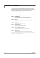
3.4 Test Procedures Ink Bleed (Dot Model) ● Procedures Turn ON the power switch while pressing the MENU and CH UP keys. Menu = A/D Adjust is displayed. Select Menu = Test, and press the key. Choose Test = Print and press the key. Select Menu = Ribbon, and press the key. Printing of six color test patterns begins. Confirm that the printed colors did not bleed. 1. 2. 3. 4. Purple Green Brown Black Blue Red * Select using the key’s action. key.
3.4 Test Procedures When the /F1 Option is Not Installed Relay Relay No. I01-I06 I11-I16 I21-I26 I31-I36 I01-I06 I11-I16 I21-I26 I31-I36 When the /F1 Option Is Installed Relay No. I01-I06 I11-I16 Chart Paper End Output Relay FAIL Output Relay I01-I06 I11-I16 I25 FAIL 3 Testing Relay Output Relays Other Than the FAIL Output Rela Select the relay number to test and confirm that it is open between the NO and relay output terminals. Press the key. The relay is energized.
3.4 Test Procedures Loop Back Test (Ethernet Communication Interface, /C7) ● Procedures This test performed when the /C7 option is specified. 1. Connect the recorder to the network. 2. Turn ON the power switch while pressing the MENU and CH UP keys. Menu = A/D Adjust is displayed. 3. Confirm that the indicator on the left of the Ethernet port on the recorder illuminates. 4. Choose Menu = Test, and press the key. key. 5. Choose Test = Loop Back and press the Confirm that OK is displayed.
Chapter 4 Adjustments 4.1 Before Making Adjustments This chapter describes adjustments of the A/D converters, recording position, pen speed (pen model), and ink ribbon (dot model). Environment See section 3.3, “Test Environment.” Operations on the Main Unit See section 3.3, “Key Operations on the Recorder.” 4 All adjustments are to be made after warming up the recorder for at least thirty minutes.
4.2 Adjustments to the Pen Model Adjusting the A/D Converters ● Overview Enter the value determined for each range, perform measurement, then write the adjusted values to the AD converter. ● Instruments Used Instrument Specifications DC voltage generator Accuracy: ±0.005% of setting + 1 µV or better Resistors 10 Ω, 50 Ω, 100 Ω, 150 Ω, 300 Ω, Accuracy: 0.
4.2 Adjustments to the Pen Model ● Procedure The following explains the procedure when working with channel 1. 1. Press the MENU and CH UP keys while turning ON the power. Menu = A/D Adjust is displayed. key. 2. With Menu = A/D Adjust is displayed, press the Menu=A/D Adjust 3. Input the password (see page 3-5). Password= 4. Select Mode = Cal/Exec, then press the Mode=Cal/Exec Select A/D No. = 1, then press the * 4 Adjustments 5. key. key. For channel 3, select A/D No. = 2. A/D No.=1 6.
4.2 Adjustments to the Pen Model 15. With End = Store displayed, press the key. The adjusted value is saved to the A/D converter. End=Store Concluding Adjustments 16. Select Menu = End, then press the mode. Menu=End key. You are returned to the operation Adjusting the Pen Speed ● Overview This is an adjustment to make the speed of the pen as it moves from left to right almost the same as when it moves from right to left. The recorder adjusts automatically.
4.2 Adjustments to the Pen Model 8. When all pen adjustments are finished, select Mode = End, then press the key. Mode=End 9. With End = Store displayed, press the The adjusted value is saved. End=Store Concluding Adjustments 10. Select Menu = End, then press the mode. Menu=End key. key. You are returned to the operation 4 If Error is displayed in the adjustment results screen, this most likely indicates that the pen cannot move normally through the full scale.
4.2 Adjustments to the Pen Model Adjusting the Zero Position 4. Select P_Adj = Zero, then press the P_Adj=Zero key. 5. Select the number of the pen to adjust, then press the The adjustment value input screen in displayed. Pen No.=1 1-4 key. 6. Adjust the numerical value so that the pen recorder position overlaps the 0% position of the z-fold chart paper. Zero=42 0/70 7. When the adjustment is complete, press the key. You are returned to the Zero/Full selection screen.
4.3 Adjustments to the Dot Model Adjusting the A/D Converters ● Overview Enter the value determined for each range, perform measurement, then write the adjusted values to the A/D converter. ● Instruments Used Instrument Specifications DC voltage generator Accuracy: ±0.005% of setting + 1 µV or better Resistors 10 Ω, 50 Ω, 100 Ω, 150 Ω, 300 Ω, Accuracy: 0.
4.3 Adjustments to the Dot Model ● Procedure 1. Press the MENU and CH UP keys while turning ON the power. Menu = A/D Adjust is displayed. 2. With Menu = A/D Adjust is displayed, press the key. Menu=A/D Adjust 3. Input the password (see page 3-6). Password= 4. Select Mode = Cal/Exec, then press the Mode=Cal/Exec 5. Select A/D No. = 1, then press the A/D No.=1 6. Select Range = 20 mV. Range=20mV 7. key. key.
4.3 Adjustments to the Dot Model Adjusting the Ink Ribbon ● Overview This is an adjustment of the position of the ink ribbon. The adjustment is performed when colors of the dots bleed into one another. ● Procedure 1. Press the MENU and Adjust is displayed. CH UP keys while turning ON the power. Menu = A/D 2. Select Menu = Aux, then press the Menu=Aux 3. Enter the password (see page 3-6), then press the Password= 4. Select Sub = Rib. shift, then press the Sub=Rib. shift 5. Select Rib.
4.3 Adjustments to the Dot Model Adjusting the Printer Position ● Overview This is an adjustment of the printer position to make the recording position 0 to 180 mm. The adjustment is performed when the recording accuracy is outside the criterion, or when internal components have been replaced. Conditions • The adjustment matches the Zero position to the 0% position of the z-fold chart paper. • It also aligns the Full position from the 0% of the z-fold chart paper to the 180 mm position.
4.3 Adjustments to the Dot Model Adjusting the Full Position key. 9. Select P_Adj = Full, then press the The adjustment value input screen in displayed. P_Adj=Full 10. Adjust the numerical value so that the pen recorder position is in alignment from the 0% position of the z-fold chart paper to the 180 mm position. Full=4 -30/30(B:1000) 11. When the adjustment is complete, press the key. You are returned to the Hysteresis/Zero/Full selection screen. 13.
4.3 Adjustments to the Dot Model Adjusting the Height of the Carriage ● Overview This is an adjustment of the clearance between the carriage and the platen. The adjustment is performed when the Adjust Shaft Assembly is replaced. ● Tools Used Gauge (B9901JZ: Carriage height adjustment clearance gauge) 1.3 mm thick (tolerance: −0.005 to −0.03 mm) 1.2 mm thick (tolerance: −0.01 to −0.035 mm) 1.1 mm thick (tolerance: −0.005 to −0.03 mm) ● Reference Value Adjustment reference value: 1.2 mm ±0.
L CN7 CN1 CN2 P.
SM 04P02B01-01E PROTECTIVE EARTH SUB POWER BOARD B8800SB CN2 CN1 P.
Chapter 6 Customer Maintenance Parts List 6.1 Customer Maintenance Parts List (Pen Model) 6 Customer Maintenance Parts List 1 3 2 4 Note: Parts marked with a SM 04P02B01-01E symbol are Customer Maintenance Parts (CMP).
6.
6.1 Customer Maintenance Parts List (Pen Model) Case and Door Assembly 2 3 4 1 10 7 5 6 6 9 8 11 Item 1 Model 437101 437102 437103 437104 Qty 2 3 4 Part No.
6.1 Customer Maintenance Parts List (Pen Model) Chart Cassette and Display Assembly 7 5 8 6 1 2 27 5 26 2 9 3 4 10 11 25 18 24 13 14 15 12 14 19 17 16 15 20 23 22 21 Description Display Assembly LED Assembly VFD Holder Screw VFD Spring Item 20 21 22 23 24 Part No.
6.1 Customer Maintenance Parts List (Pen Model) Frame and Chart Motor Assembly 2 1 3 3 6 5 6 7 18 9 4 17 9 6 5 6 13 14 16 15 Item 1 2 3 4 5 Part No.
6.
6.1 Customer Maintenance Parts List (Pen Model) Pen Servo and Plotter Assembly (2/2) Model 437101 437102 437103 437104 Qty Part No.
6.
6.1 Customer Maintenance Parts List (Pen Model) CPU and Rear Panel Assembly (2/2) Item 1 2 Model 437101 437102 437103 437104 Qty 3 4 5 Part No.
6.
6.1 Customer Maintenance Parts List (Pen Model) Terminal Assembly (2/3) Part No.
6.
6.1 Customer Maintenance Parts List (Pen Model) Standard Accessories 6 4 7 1 8 2 9 5 10 Part No.
6.1 Customer Maintenance Parts List (Pen Model) Portable Type ( /H5[ ]) 6 5 7 8 9 10 5 055 0/ 24 V 60 0V A H M z A X 1 10 11 12 13 14 15 16 17 16 18 19 20 2 3 25 24 13 4 6-14 Item 1 2 3 4 5 Part No.
6.2 Customer Maintenance Parts List (Dot Model) 6 7 8 9 10 11 12 13 14 15 16 17 18 Note: Parts marked with a SM 04P02B01-01E Customer Maintenance Parts List 1 2 3 4 5 6 19 20 21 22 23 24 symbol are Customer Maintenance Parts (CMP).
6.
6.2 Customer Maintenance Parts List (Dot Model) Case and Door Assembly 2 3 4 1 10 7 5 6 6 Customer Maintenance Parts List 12 9 8 11 Item 1 Model 437106 437112 437118 437124 Qty 2 3 4 Part No.
6.2 Customer Maintenance Parts List (Dot Model) Chart Cassette and Display Assembly 7 5 8 6 1 2 27 5 26 2 9 3 4 10 11 25 18 24 13 14 15 12 14 19 17 16 15 20 23 22 21 Item 1 2 3 4 5 Part No. B8802CA B8800CR B8802DF Y9308LB B8802DG Qty 1 2 1 1 3 6 7 8 9 10 B9905XW B9988DL B8802DB B9905GZ B9905HA 11 12 13 14 15 16 17 18 19 Description Display Assembly LED Assembly VFD Holder Screw VFD Spring Item 20 21 22 23 24 Part No.
6.2 Customer Maintenance Parts List (Dot Model) Frame and Chart Motor Assembly 1 2 3 6 4 7 8 4 10 9 10 22 11 6 12 21 Customer Maintenance Parts List 13 5 13 10 9 10 17 18 20 SM 04P02B01-01E 19 15 16 14 Description Dot Driver PCB Shift Sensor Assembly FPC Clamp Screw Nut (M4) Item 1 2 3 4 5 Part No.
6.
6.2 Customer Maintenance Parts List (Dot Model) Frame and Carriage Assembly (2/2) Item 1 2 3 4 5 Part No.
6.
6.
6.
6.2 Customer Maintenance Parts List (Dot Model) Terminal Assembly (2/5) Item 1 Part No.
6.2 Customer Maintenance Parts List (Dot Model) Terminal Assembly (3/5) Item 25 26 27 28 29 30 31 32 33 34 35 36 37 38 39 40 Part No.
6.
6.
6.2 Customer Maintenance Parts List (Dot Model) Standard Accessories 6 7 1 4 8 2 9 5 10 3 Part No.
6.2 Customer Maintenance Parts List (Dot Model) Portable Type ( /H5[ ]) 6 5 7 8 9 10 0 5 55 0/6 24 VA 0 0V H M z A X 1 10 11 12 13 14 15 16 17 16 18 19 20 2 3 4 6-30 25 24 13 Item 1 2 3 4 5 Part No.
Chapter 7 Replacing Parts 7.1 Before Replacing Parts Notes When Replacing Parts • Replacement of parts can only be performed by properly trained personnel. • This section describes disassembly of the instrument. Refer to the disassembly procedures when reassembling. • If parts other than the chart paper, pens, ribbon cassette, and internal light LED are replaced, the instrument is no longer warranted by YOKOGAWA.
7.2 Replacable Parts The recommended replacement periods for wearable parts (ones with limited lifespans) is given in the table below. The replacement periods are based on standard operating conditions. The actual replacement period should be determined depending on the actual operating conditions. Pen Model Quantity Used Item Replacement Part Name Period Part No.
7.3 Disassembly Procedure (Common Items) This is a description of the disassembly procedures that are common to the dot and pen models. The photographs are of the dot model, but the pen model has the same structure and the same procedures can be used. Internal Unit - Frame Assembly [Item 10 on pages 6-2 and 6-16] 1. 2. Remove the Chart Cassette Assembly. Sufficiently loosen screw (A), then remove screw (B). (Screw tightening torque: 0.88 to 0.98 N·m). Screw (A) 7 Screw (B) Replacing Parts 3.
7.3 Disassembly Procedure (Common Items) 5. Loosen the screw on the back of the FPC and open the internal unit. (Screw tightening torque: 0.88 to 0.98 N·m). Screw Remove the Internal Unit 6. Remove the four screws from the hinges, and remove the internal unit from the case. (Screw tightening torque: 1.37 to 1.47 N·m).
7.3 Disassembly Procedure (Common Items) Display Assembly (B8802CA) [Item 1 on pages 6-4 and 6-18] 1. 2. Open the internal unit. Remove the Display Assembly FPC from the Pen Driver PCB (CN5)/Dot Driver PCB (CN7). Pen/Dot Driver PCB FPC Lift the cable lock. Remove the FPC. Cable Lock 3. Remove the FPC Clamp from the internal unit, and pull the FPC out from the FCP Clamp. 7 Replacing Parts FPC Clamp FPC Clamp and FPC as a set 4.
7.3 Disassembly Procedure (Common Items) 5. Pull the Display Assembly toward you, then pull the support point on the right side of the Display Assembly. Pull Support point 6. Remove the Display Assembly. Battery Assembly (B9905WD) [Item 15 on page 6-8 and item 16 on page 6-22] 1. 2. Open the internal unit. Remove the Battery Assembly cable while holding down the CPU Assembly connector (CN1) and cable. Battery Assembly Connector 3. Release the Clamp latch, then remove the Battery Assembly.
7.3 Disassembly Procedure (Common Items) Chart Paper Feed Motor (B9905GS) [Item 11 on page 6-5 and itme 15 on page 6-19] 1. 2. 3. Remove the internal unit. Remove the Motor Assembly cable from the Pen Driver PCB (CN8)/Dot Driver PCB (CN9). Remove the pins from the two locations while holding the Motor Assembly cable. Pin Pin 4. Push the left edge of the bracket, then slide the entire bracket to the right while releasing the latch, and remove the bracket.
7.4 Disassembly Procedure (Pen Model) Plotter Carriage (B9905NB) [Item 22 on page 6-6] Plotter Motor (B9905NS) [Item 27 on page 6-6] Lever Assembly (B9900RH) [Item 39 on page 6-6] 1. 2. 3. Open the internal unit. Remove the Motor Cable extruding from the Plotter Assembly from the Pen Driver PCB (CN3 and CN4). Remove the two screws securing the Plotter Assembly. (Screw tightening torque: 0.59 to 0.69 N·m). Motor Cable Screw Screw FPC 4. Pull out the Plotter Assembly. 5.
7.4 Disassembly Procedure (Pen Model) 6. Remove the two screws securing the Shaft. (Screw tightening torque: 0.59 to 0.69 N·m). Main Shaft Screw 7. Screw Remove the Belt, then pull the Frame to widen, and remove the Shaft. Shaft Plotter Carriage 7 Replacing Parts Removing the Plotter Motor 8. Remove the two screws securing the Plotter Motor. (Screw tightening torque: 0.20 to 0.26 N·m). Screw Screw Removing the Lever Assembly 8. Remove the screw securing the Lever Assembly.
7.4 Disassembly Procedure (Pen Model) Pen Servo Assembly (B8802EF) [Item 2 on page 6-6] CAUTION • If any foreign material adheres to the mechanism of the Pen Servo Assembly that moves the pen carriage, malfunction can occur. • If any foreign material adheres to the bottom of the Pen Servo Assembly, that foreign material can fall onto components during assembly and cause malfunction.
7.4 Disassembly Procedure (Pen Model) 5. Remove the screw securing the Pen Base Bracket and Servo Top Cover. (Screw tightening torque: 0.39 to 0.49 N·m). Screw 6. Remove the Servo Top Cover from the Pen Base Bracket. 7. Remove the FPCs connected to the Pen Servo PBCs. 7 8. Replacing Parts FPC Remove the Pen Servo PCBs which are secured by latches to the Pen Servo Assembly.
7.4 Disassembly Procedure (Pen Model) 9. Remove the three pins securing the Pen Servo Assembly. The tips of the pins form latches. To remove them, squeeze the tips using a pair of tweezers, then pull out the pins. Pin 10. Latch Remove the Pins from the Pen Base Bracket, then remove the Pen Servo Assembly. Pin Latch 11. Remove the Pen Arm Assembly while pushing the Pen Arm Shaft of the Pen Servo Assembly. Pen Arm Assembly Arm No.
7.4 Disassembly Procedure (Pen Model) 12. Pull out the Pen Arm Shaft and Spring from the Pen Carriage.
7.5 Disassembly Procedure (Dot Model) Ribbon Feed Motor (B9906GL) [Item 22 on page 6-20] Ribbon Feed Gear (B9906GN, B9901HM, B9901HN) [Items 19 to 21 on page 6-20] 1. Remove the internal unit. Ribbon Holder Assembly 2. 3. Remove the Ribbon Feed Motor cable from the Dot Driver PCB (CN5). Remove the three pins and four screws that secure the Plate, then remove the Plate. Plate Screw Screw Screw Screw Pin 4.
7.5 Disassembly Procedure (Dot Model) 5. Remove the latch from the Holder Lock on the right panel, then slide it to the left side and remove the Holder Lock. Latch Holder Lock Latch 6. Pull the Ribbon Holder Assembly toward you and remove. 7 Disconnect the Band that holds the cables in place. Remove the two latches securing the Ribbon Feed Motor, then turn clockwise and remove the Ribbon Feed Motor. Band Latch Latch Ribbon Feed Motor 8.
7.5 Disassembly Procedure (Dot Model) Carriage Assembly (B8803BB) [Item 24 on page 6-20] Pully (B9901EY) [Item 30 on page 6-20] CAUTION Do not apply lubricant to the Shaft. 1. 2. 3. Remove the internal unit. Remove the FPC extruding from the Carriage Assembly from the Dot Driver PCB (CN6). Remove the three pins and four screws that secure the Plate, then remove the Plate. Plate Screw Screw Screw Screw Pin 4. Remove the screw securing the FPC. (Screw tightening torque: 0.59 to 0.69 N·m). Screw 5.
7.5 Disassembly Procedure (Dot Model) 6. Remove the two screws securing the Pulley Bracket. (Screw tightening torque: 0.59 to 0.69 N·m). Pulley Bracket Screw Screw Removing the Pulley 7. Release the Pulley Bracket latch. Remove the Belt from the Pulley Assembly. Collar Latch Pulley Shaft Pulley Assembly Main Shaft Adjust Shaft Assembly Screw When removing the Adjust Shaft Assembly, see section 4.3, “Adjusting the Height of the Carriage.
7.5 Disassembly Procedure (Dot Model) Carriage Motor (B9906FX) [Item 13 on page 6-20] 1. 2. 3. Remove the internal unit. Remove the cable extruding from the Carriage Assembly from the Dot Driver PCB (CN8). Remove the three pins and four screws that secure the Plate, then remove the Plate. Plate Screw Screw Screw Screw Pin 4. Move the Carriage Motor to the right to loosen the Belt tension, then remove the Belt from the Carriage Motor Pulley. Carriage Motor Belt 5.
7.5 Disassembly Procedure (Dot Model) 7. Remove the two screws and M3 hex screw, remove the Plate and Drive Pulley. (Screw tightening torque: 0.59 to 0.69 N·m, M3 hex screw tightening torque: 0.20 to 0.26 N·m). Plate M3 Hex Screw Screw Screw Drive Pulley Ribbon Shift Motor - Ribbon Swing Motor (B9906FS) [Item 8 on page 6-19] Ribbon Shift Gear Box - Ribbon Swing Gear Assembly (B8803BS) [Item 7 on page 6-19] 1. 2. 3. Remove the internal unit.